Page is loading ...

Owner’s Manual
Light Tower
MLT4060DOTM • MLT4060DOTK
SAVE THIS MANUAL FOR FUTURE REFERENCE

ii Owner’s Manual for MLT Light Tower
Use this page to record important information about your Light Tower
Record the information found on your unit data label on
this page. See unit serial number location (Unit Serial
Number Locations). The label plate is affixed to the
inside partition, to the left of the control panel console.
Engine and generator serial numbers are located on
separate data plates affixed to the engine and generator
respectively.
When contacting an Generac Mobile Products
Authorized Service Dealer about parts and service,
always supply the complete model number and serial
number of the unit.
Operation and Maintenance: Proper maintenance and
care of the Light Tower ensures a minimum number of
problems and keeps operating expenses at a minimum. It
is the operator’s responsibility to perform all safety
checks, to verify that all maintenance for safe operation is
performed promptly, and to have the equipment checked
periodically by a Generac Mobile Products Authorized
Service Dealer. Normal maintenance, service and
replacement of parts are the responsibility of the owner
or operator and, as such, are not considered defects in
materials or workmanship within the terms of the
warranty. Individual operating habits and usage may
contribute to the need for additional maintenance or
service.
Unit Model Number
Unit Serial Number
Engine Model
Number
Engine Serial
Number
Generator Model
Number
Generator Serial
Number
(000005)
WARNING
California Proposition 65. This product contains or
emits chemicals known to the state of California to
cause cancer, birth defects, and other reproductive
harm.
(000004)
WARNING
California Proposition 65. Engine exhaust and some
of its constituents are known to the state of California
to cause cancer, birth defects, and other reproductive
harm.

Owner’s Manual for MLT Light Tower iii
Section 1: Introduction and Safety
Introduction ..........................................................1
Read This Manual Thoroughly ....................................1
How to Obtain Service .................................................1
Safety Rules .........................................................1
General Hazards ..................................................2
Explosion and Fire Hazards ................................2
Trailer Hazards .....................................................2
Electrical Hazards ................................................3
Battery Hazards ...................................................3
Fuel Hazards ........................................................4
Engine Safety .......................................................4
Operating Safety ..................................................4
Positioning the Unit .....................................................4
Starting the Unit ...........................................................4
Raising and Lowering the Mast ...................................5
Service Safety ......................................................5
Towing Safety ......................................................6
Hitch and Coupling ......................................................6
Running Lights ............................................................6
Wheels and Tires ........................................................6
Safe Towing Techniques .............................................6
Reporting Trailer Safety Defects ........................6
Section 2: General Information
Specifications ......................................................7
Unit Serial Number Locations ............................8
Control Panel .......................................................9
Control Panel Features and Functions ......................10
Section 3:Operation
Light Tower Setup .............................................11
Flagger Station Setup ........................................12
Prestart Checklist ..............................................12
Raising the Mast ................................................13
Starting the Unit .................................................14
Automatic Shutdown .........................................14
Light Operation ..................................................15
Receptacle Panel ............................................... 15
Engine Derating ................................................. 15
Voltage Regulation (Optional) .......................... 15
Wet Stacking ...................................................... 16
Shutting Down the Unit ..................................... 16
Lowering the Mast ............................................. 16
Removing the Lights for Transportation ......... 17
Towing the Unit ................................................. 17
Lifting the Unit ................................................... 17
Section 4:Maintenance
Emissions Information ...................................... 19
Daily Walk-Around Inspection ......................... 19
General Maintenance ........................................ 19
Preparing for Service .................................................19
Cleaning the Unit .......................................................19
Inspecting the Unit .....................................................19
Basic Maintenance Schedule ........................... 20
Winch Use, Operation and Maintenance ......... 22
Prior to Use ...............................................................22
Operation ...................................................................22
Maintenance ..............................................................22
Optional Lower Radiator Hose Heater Use and
Maintenance ....................................................... 23
Trailer Wheel Bearings ..................................... 23
Jack Maintenance .............................................. 23
Section 5:Troubleshooting
General Troubleshooting .................................. 25
Troubleshooting the Lights .............................. 26
Section 6:Wiring Diagrams
Mast Junction Box Wiring and Light
Connections ....................................................... 27
AC Wiring Diagram ............................................ 28
DC Wiring Diagram—Mitsubishi ...................... 29
DC Wiring—Kubota ........................................... 30
DC Wiring Diagrams for Optional Equipment . 31
Table of Contents


Introduction and Safety
Owner’s Manual for MLT Light Tower 1
Section 1: Introduction and Safety
Introduction
Thank you for purchasing a Generac Mobile Products LLC
product. This unit has been designed to provide high
performance, efficient operation, and years of use when
maintained properly.
The information in this manual is accurate based on
products produced at the time of publication. The
manufacturer reserves the right to make technical updates,
corrections, and product revisions at any time without
notice.
Read This Manual Thoroughly
If any section of the manual is not understood, contact your
nearest Generac Mobile Products Authorized Service
Dealer, or contact
Generac Mobile Products LLC at 1-800-
926-9768, or
Generac Mobile Products Technical Service at
1-800-926-9768 or
www.generacmobileproducts.com
with any questions or concerns.
The owner is responsible for proper maintenance and safe
use of the equipment. Comply with regulations the
Occupational Safety and Health Administration (OSHA)
has established, or with equivalent standards. Also, verify
that the unit is applied, used, and maintained in accordance
with the manufacturer's instructions and recommendations.
Do nothing that might alter safe application/usage and
render the unit in noncompliance with the aforementioned
codes, standards, laws, and regulations
.
Save these instructions for future reference. This manual
contains important instructions for the unit that should be
followed during setup, operation and maintenance of the
unit and battery. ALWAYS supply this manual to any
individual that will use this machine.
How to Obtain Service
When the unit requires servicing or repairs, contact a
Generac Mobile Products Authorized Dealer for assistance.
Service technicians are factory-trained and are capable of
handling all service needs. For assistance locating a dealer,
go to
www.generacmobleproducts.com/parts-service/
find-service
.
When contacting a Generac Mobile Products
Authorized Dealer about parts and service, always supply
the complete model number and serial number of the unit
as given on its data decal located on the unit. Record the
model number and serial numbers in the spaces provided
on the inside front cover of this manual.
Safety Rules
The manufacturer cannot anticipate every possible
circumstance that might involve a hazard. The warnings in
this manual, and on tags and decals affixed to the unit are,
therefore, not all inclusive. If using a procedure, work
method or operating technique that the manufacturer does
not specifically recommend, verify that it is safe for others.
Also make sure the procedure, work method or operating
technique utilized does not render the equipment unsafe.
Throughout this publication, and on tags and decals affixed
to the unit, DANGER, WARNING, CAUTION and NOTE
blocks are used to alert personnel to special instructions
about a particular operation that may be hazardous if
performed incorrectly or carelessly. Observe them
carefully. Their definitions are as follows:
NOTE: Notes contain additional information important to
a procedure and will be found within the regular text of
this manual.
These safety alerts cannot eliminate the hazards that they
indicate. Common sense and strict compliance with the
special instructions while performing the action or service
are essential to preventing accidents.
(000100a)
WARNING
Consult Manual. Read and understand manual
completely before using product. Failure to
completely understand manual and product
could result in death or serious injury.
(000001)
DANGER
Indicates a hazardous situation which, if not avoided,
will result in death or serious injury.
(000002)
WARNING
Indicates a hazardous situation which, if not avoided,
could result in death or serious injury.
(000003)
CAUTION
Indicates a hazardous situation which, if not avoided,
could result in minor or moderate injury.

Introduction and Safety
2 Owner’s Manual for MLT Light Tower
General Hazards
Explosion and Fire Hazards
Trailer Hazards
Asphyxiation. Running engines produce
carbon monoxide, a colorless, odorless,
poisonous gas. Carbon monoxide, if not
avoided, will result in death or serious injury.
(000103)
DANGER
(000107)
WARNING
Hearing Loss. Hearing protection is
recommended when using this machine.
Failure to wear hearing protection could
result in permanant hearing loss.
(000111)
WARNING
Moving Parts. Keep clothing, hair, and
appendages away from moving parts. Failure
to do so could result in death or serious injury.
(000108)
WARNING
Hot Surfaces. When operating machine, do not
touch hot surfaces. Keep machine away from
combustibles during use. Hot surfaces could
result in severe burns or fire.
WARNING
Risk of injury. Do not operate or service this machine
if not fully alert. Fatigue can impair the ability to service
this equipment and could result in death or serious
injury.
(000215)
(000139)
WARNING
Risk of burns. Allow engine to cool before
draining oil or coolant. Failure to do so could
result in death or serious injury.
(000105)
DANGER
Explosion and Fire. Fuel and vapors are
extremely flammable and explosive. Add fuel
in a well ventilated area. Keep fire and spark
away. Failure to do so will result in death
or serious injury.
(000147)
WARNING
Risk of Fire. Unit must be positioned in a
manner that prevents combustible material
accumulation underneath. Failure to do so
could result in death or serious injury.
(000110)
WARNING
Risk of Fire. Hot surfaces could ignite
combustibles, resulting in fire. Fire could
result in death or serious injury.
WARNING
Trailer must be securely coupled to the hitch and the
chains correctly attached. Uncoupled or unchained
towing could result in death or serious injury.
(000233)
WARNING
Do not operate this unit while transporting. Doing so
could result in death or serious injury.
(000231)
(000234a)
WARNING
Crushing hazard. Verify unit is properly secured and
on level ground. An unsecured unit can suddenly roll
or move, causing death or serious injury.
WARNING
Property or Equipment Damage. Tighten wheel lug
nuts after first 50 miles to factory specifications.
Failure to do so could result in death, serious injury,
property or equipment damage.
(000235)

Introduction and Safety
Owner’s Manual for MLT Light Tower 3
Electrical Hazards Battery Hazards
Always recycle batteries in accordance with local laws and
regulations. Contact your local solid waste collection site
or recycling facility to obtain information on local recycling
processes. For more information on battery recycling, visit
the Battery Council International website at: http://
batterycouncil.org
(000145)
DANGER
Electrocution. In the event of electrical accident,
immediately shut power OFF. Use non-conductive
implements to free victim from live conductor. Apply
first aid and get medical help. Failure to do so will
result in death or serious injury.
(000104)
DANGER
Electrocution. Water contact with a power
source, if not avoided, will result in death
or serious injury.
(000144)
DANGER
Electrocution. Contact with bare wires,
terminals, and connections while generator
is running will result in death or serious injury.
(000152)
DANGER
Electrocution. Verify electrical system is
properly grounded before applying power.
Failure to do so will result in death or serious
injury.
(000188)
DANGER
Electrocution. Do not wear jewelry while
working on this equipment. Doing so will
result in death or serious injury.
DANGER
Electrocution. DO NOT use the unit if
electrical cord is cut or worn through. Doing
so will result in death or serious injury.
(000263a)
(000188)
DANGER
Electrocution. Do not wear jewelry while
working on this equipment. Doing so will
result in death or serious injury.
(000137a)
WARNING
Explosion. Batteries emit explosive gases while charging.
Keep fire and spark away. Wear protective gear when
working with batteries. Failure to do so could result in
death or serious injury.
(000162)
WARNING
Explosion. Do not dispose of batteries in a fire. Batteries
are explosive. Electrolyte solution can cause burns and
blindness. If electrolyte contacts skin or eyes, flush with water
and seek immediate medical attention.
(000163a)
WARNING
Risk of burn. Do not open or mutilate batteries.
Batteries contain electrolyte solution which can
cause burns and blindness. If electrolyte contacts
skin or eyes, flush with water and seek immediate
medical attention.
WARNING
Environmental Hazard. Always recycle batteries at an
official recycling center in accordance with all local
laws and regulations. Failure to do so could result in
environmental damage, death or serious injury.
(000228)

Introduction and Safety
4 Owner’s Manual for MLT Light Tower
Fuel Hazards
• DO NOT fill fuel tank near an open flame, while
smoking, or while engine is running. DO NOT fill
tank in an enclosed area with poor ventilation.
• DO NOT operate with the fuel tank cap loose or
missing.
Engine Safety
Internal combustion engines present special hazards
during operation and fueling. Failure to follow the safety
guidelines described below could result in severe injury or
death. Read and follow all safety alerts described in the
engine operator's manual. A copy of this manual was
supplied with the unit when it was shipped from the factory.
• DO NOT run engine indoors or in an area with poor
ventilation. Make sure engine exhaust cannot seep
into closed rooms or ventilation equipment.
• DO NOT clean air filter with gasoline or other types
of low flash point solvents.
• DO NOT operate the unit without a functional
exhaust system.
• Shut the engine down if any of the following
conditions exist during operation:
• Noticeable change in engine speed.
• Loss of electrical output.
• Equipment connected to the unit overheats.
• Sparking occurs.
• Engine misfires or there is excessive engine/
generator vibration.
• Protective covers are loose or missing.
• Ambient air temperature is above 120°F (49°C).
Operating Safety
Positioning the Unit
•
The area immediately surrounding the unit should
be dry, clean, and free of debris.
• Position and operate the unit on a firm, level
surface.
• If the unit is equipped with a frame grounding stud,
follow the National Electrical Code (NEC), state,
and local regulations when connecting.
Starting the Unit
(000192)
DANGER
Explosion and fire.Fuel and vapors are extremely
flammable and explosive. No leakage of fuel is
permitted. Keep fire and spark away. Failure to do
so will result in death or serious injury.
(000174)
DANGER
Risk of fire. Allow fuel spills to completely dry
before starting engine. Failure to do so will
result in death or serious injury.
(000260a)
High Voltage. Verify area above unit is clear
of overhead wires and obstructions. Contact
with high-voltage power lines will result in
death or serious injury.
DANGER
(000277)
WARNING
Burn hazard. Never operate lights with a
damaged or missing lens cover. Lamps are
hot and pressurized while in use. Unprotected
lamps can shatter, causing severe injury.
DANGER
Electrocution. DO NOT use the unit if
electrical cord is cut or worn through. Doing
so will result in death or serious injury.
(000263a)
CAUTION
(000291)
Equipment damage. Do not attempt to start or operate
a unit in need of repair or scheduled maintenance.
Doing so could result in serious injury, death, or
equipment failure or damage.
WARNING

Introduction and Safety
Owner’s Manual for MLT Light Tower 5
Raising and Lowering the Mast
•
Keep area around the unit clear of people while
raising and lowering the mast.
• ALWAYS lower the mast when not in use.
• The tower extends up to 30 ft (9.14 m). Make sure
area above trailer is open and clear of overhead
wires and obstructions.
• If for any reason any part of mast hangs up or
winch cable develops slack while raising or
lowering tower, STOP immediately! Contact an
IASD.
• NEVER remove safety pin or pull mast locking pin
while tower is up.
Service Safety
This unit uses high voltage circuits capable of causing
serious injury or death. Only a qualified and licensed
electrician should troubleshoot or repair problems
occurring in this equipment.
•
Before servicing the unit, verify the Control Power
switch and circuit breakers are in the OFF (O)
position, and the negative (-) terminal on the battery
is disconnected.
DO NOT
perform even routine
service (oil/filter changes, cleaning, etc.) unless all
electrical components are shut down.
•
ALWAYS
use extreme caution when servicing this
unit in damp conditions. Do not service the unit if your
skin or clothing is wet. Do not allow water to collect
around the base of the unit.
•
DO NOT
wash the unit with high pressure hoses,
power washers, or steam cleaners. Water may
collect in the unit, causing damage to electrical parts.
•
Replace all missing and hard to read decals. Decals
provide important operating instructions and warn of
dangers and hazards.
•
Wear heavy leather gloves when handling winch
cables. Never let cables slip through bare hands.
•
Only use mild soap and water to clean the lens covers.
Other chemicals may damage the lens covers.
•
Verify slings, chains, hooks, ramps, jacks and other
types of lifting devices are attached securely and
have enough weight-bearing capacity to lift or hold
the equipment safely. Always remain aware of the
position of other people around you when lifting the
equipment.
WARNING
Electrocution. Do not set up or operate
this unit if severe weather is expected.
Lightning strikes can kill or cause severe injury
even if you are not touching the unit.
(000296)
WARNING
(000297)
> 60 mph> 60 mph
Do not set up the unit if high winds
are expected. High winds can cause the
unit to tip or fall, causing severe injury
or machine damage.
(000279)
Personal injury or equipment damage. Do not raise
or lower the mast while the unit is operating.
Doing so can break the lenses and cause the
lamps to shatter.
WARNING
WARNING
Personal Injury. Stop immediately if the mast hangs
up or the winch cable develops slack. Excess slack
could cause the mast to collapse, resulting in personal
injury or equipment damage.
(000265)
WARNING
Tipping hazard. Extend the outriggers and level the unit
before raising the mast. Keep the outriggers extended
while the mast is up. Failure to do so could cause the unit
to tip and fall and could result in death or serious injury.
(000266)
(000278)
WARNING
Burn hazard. Lamps become extremely hot
while in use. Allow 10–15 minutes for cooling
before handling or lowering mast. Touching a
hot lens or fixture can cause severe burns.

Introduction and Safety
6 Owner’s Manual for MLT Light Tower
Towing Safety
Towing a trailer requires care. Both the trailer and vehicle
must be in good condition and securely fastened to each
other to reduce the possibility of an accident. Some states
require that large trailers be registered and licensed.
Contact your local Department of Transportation office to
check on license requirements for your particular unit.
Hitch and Coupling
•
Verify the hitch and coupling on the towing vehicle
are rated equal to, or greater than, the trailer's
Gross Vehicle Weight Rating (GVWR).
• Verify the trailer hitch and the coupling are
compatible. Make sure the coupling is securely
fastened to the vehicle.
• DO NOT tow trailer using defective parts. Inspect
the hitch and coupling for wear or damage.
• Connect safety chains in a crossing pattern under
the tongue.
• Before towing the trailer, verify that the weight of
the trailer is equal across all tires. On trailers with
adjustable height hitches, adjust the angle of the
trailer tongue to keep the trailer as level as
possible.
• Attach the breakaway cable to the rear bumper of
the towing vehicle.
Running Lights
Verify directional and brake lights on the trailer are
connected and working properly
Wheels and Tires
•
Check trailer tires for wear and proper inflation.
• Verify wheel lug nuts are present and tightened to
the specified torque.
Safe Towing Techniques
•
Practice turning, stopping and backing up in an
area away from heavy traffic prior to transporting
the unit.
• Maximum recommended speed for highway towing
is 45 mph (72 km/h). Recommended off-road
towing speed is 10 mph (16 km/h) or less,
depending on terrain.
• When towing, maintain extra space between
vehicles and avoid soft shoulders, curbs and
sudden lane changes.
Reporting Trailer Safety Defects
If you believe your trailer has a defect which could cause
a crash or could cause injury or death, you should
immediately inform the National Highway Traffic Safety
Administration (NHTSA) in addition to notifying Generac
Mobile Products LLC.
If NHTSA receives similar complaints, it may open an
investigation; and if it finds that a safety defect exists in a
group of vehicles, it may order a recall and remedy
campaign. However, NHTSA cannot become involved in
an individual problem between you, your dealer, or
Generac Mobile Products LLC.
To contact NHTSA, you may either call the Auto Safety
Hotline toll-free at 1-888-327-4236 (TTY:1-800-424-9153),
go to http://www.safercar.gov; or write to:
Administrator
NHTSA
1200 New Jersey Avenue S.E.
Washington, DC 20590
You can also obtain other information about motor vehicle
safety from http://www.safercar.gov.

General Information
Owner’s Manual for MLT Light Tower 7
Section 2: General Information
Specifications
DESCRIPTION UNITS MLT4060DOTM MLT4060DOTK
Engine
Make/Brand — MITSUBISHI KUBOTA
Model — L3E-W461ML D1005-E3BG1-MGM-1
EPA Tier 4f 4f
Type — Diesel, liquid cooled, 4-stroke
Horsepower - prime hp (kW) 10.5 (7.8) 11.7 (8.7)
Horsepower - standby hp (kW) 12.2 (9.1) 13.1 (9.8)
Operating Speed rpm 1800 1800
Displacement
in
3
(L)
57.97 (0.95) 61.08 (1.00)
Cylinders qty 3 3
Fuel Consumption—100% Prime gph (Lph) 0.47 (1.78) 0.50 (1.89)
Battery Type—Group Number — 24 24
Battery Voltage quantity per unit 12V (1) 12V (1)
Battery Rating CCA-hour 440 440
Generator
Make/Brand — Marathon Electric Marathon Electric
Model — 201CSA5411 201CSA5411
Type, Insulation — Brushless, F Brushless, F
Output kW (kVA) 6.0 (6.0) 6.0 (6.0)
Output Voltage volts 120/240, single phase 120/240, single phase
Output Amperes 120V (240V) amperes 50 (25) 50 (25)
Frequency Hz Hertz 60 60
Power Factor — 1 (1Ø) 1 (1Ø)
Sound (23 ft at prime) dB (A) 70 70
Weights
Dry Weight lbs (kg) 1675 (760) 1695 (770)
Operating Weight lbs (kg) 1888 (856) 1908 (866)
Capacities
Fuel Tank Volume gal (L) 30 (114) 30 (114)
Usable Fuel Volume gal (L) 30 (114) 30 (114)
Coolant (including engine) qt (L) 4.8 (4.5) 4.8 (4.5)
Oil (including filter) qt (L) 3.8 (3.6) 3.8 (3.6)
Maximum Run Time hours 64 60
AC Distribution
Circuit Breaker Size amperes 30 30
Voltage Regulation — Capacitor +/-6% Capacitor +/-6%
Voltages Available 1Ø — 120, 240 120, 240
Lighting
Lighting Type — Metal Halide Metal Halide
Ballast Type — Coil & Core Coil & Core
Lumens — 292,000-306,600 292,000-306,600
Dimensions
Length w/ mast stowed in (m) 170 (4.32) 170 (4.32)
Width in (m) 68 (1.73) 68 (1.73)
Width w/ outriggers extended in (m) 140 (3.56) 140 (3.56)
Height w/ mast stowed in (m) 70 (1.78) 70 (1.78)
Maximum height of tower ft (m) 30 (9.14) 30 (9.14)
Trailer
Number of Axles 1 1
Capacity - Axle Rating lbs (kg) 2200 (988) 220 (998)
Tire Size in 13 13
Hitch—Standard — 2” Ball 2” Ball
Maximum Tire Pressure psi 50 50
Specifications are subject to change without notice.

General Information
8 Owner’s Manual for MLT Light Tower
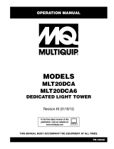
Unit Serial Number Locations
Refer to the illustration to locate the unit ID tag and
Vehicle Identification Number (VIN) tag on the unit.
Important information, such as the unit serial number,
model number, VIN and tire loading information are found
on these tags. Record the information from these tags so
it is available if the tags are lost or damaged. When
ordering parts or requesting assistance, you may be
asked to provide this information.
Figure 2-1. Serial Number Locations
Unit ID Tag
Located on inside
of front panel.
V.I.N. Tag
TIRE AND LOADING INFORMATION
RENSEIGNEMENTS SUR LES
PNEUS ET LE CHARGEMENT
SEE OWNER’S
MANUAL FOR
ADDITIONAL
INFORMATION
VOIR LE
MANUEL DE
L’USAGER
POUR
PLUS DE
RENSEIGNEMENTS
MANUFACTURED BY/FABRIQUE PAR: Generac Mobile Products DATE: 00/0000
GVWR/PNBV: 000KG (0000LBS) COLD INF. PRESS./
PRESS. DE
V.I.N./N.I.V.:
00000000000000000
TYPE:
TRAILER
MODEL:
XXX000
GAWR / PNBE TIRE / PNEU RIM / JANTE GONF A FROID - KPA(PSI/LPC) SGL / DUAL
EACH
AXLE
THIS VEHICLE CONFORMS TO ALL APPLICABLE STANDARDS PRESCRIBED UNDER THE U.S. FEDERAL MOTOR VEHICLE SAFETY STANDARDS(FMVSS) AND CANADIAN
MOTOR VEHICLE SAFETY REGULATIONS IN EFFECT ON THE DATE OF MANUFACTURE.
CE VEHICULE EST CONFORME A TOUTES LES NORMES QUI LUI SONT APPLICABLES EN VERTU DU REGLEMENT SUR LA SECURITE DES VEHICULES AUTOMOBILES DU CANADA EN VIGUEUR A LA DATE SA
FABRICATION.
The weight of cargo should never exceed 0000KG (0000LBS)
Le poids du chargement ne doit jamais depasser 0000KG (0000LBS)
Manufactured by Generac Mobile
Products LLC
(920)361-4442 (800)926-9768
MODEL
WEIGHT COUNTRY OF ORIGIN
SERIAL NUMBER
MANUFACTURING CODE
Form: SFC626A
004600

General Information
Owner’s Manual for MLT Light Tower 9
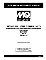
Control Panel
Figure 2-2. Control Panel
120V
240V
DC
BREAKER
TURN
MAIN
BREAKER
OFF
120V
BREAKER
MAIN
BREAKER
240V
BALLAST INDICATOR LIGHTS
MAST LIGHT SWITCHES
I
O
I
O
I
O
I
O
NEUTRAL BONDED TO FRAME
ON
ON
ON ON ON ON
GLOW PLUG
INDICATOR
OFF
RUN
START
GLOW
PLUG
400W 400W
Flagger Station Switches
A C
B
D
004548
F
E
G
H
I
J
K

General Information
10 Owner’s Manual for MLT Light Tower
Control Panel Features and Functions
(A) Main Circuit Breaker
This 240V (30A) breaker will disconnect power to the
lights and receptacle panel. It will also disable the starting
circuit if engine starting is attempted when the main
breaker is on.
(B) Light Switches
One circuit breaker is supplied for each light.
(C) Ballast Indicator Lights
Indicates power from the ballast to each light
.
(D) Engine Starting Switch
Keyed switch operates glow plugs, starts and stops
engine.
(E) Glow Plug Indicator
Indicates operation of the engine glow plugs (Mitsubishi
engines only).
(F) Engine Hour Meter
Keeps track of engine hours for service.
(G) DC Circuit Breaker
Circuit breaker (10A) for the engine electrical system.
(H) 240V Twist-Lock Receptacle
This 240V (30A) receptacle supplies power for
accessories connected to the generator when the engine
is running and the main circuit breaker is switched to the
ON (I) position.
(I) 120V GFCI Receptacle
This unit is equipped with one 120V (20A) GFCI
receptacle to supply power for accessories connected to
the generator when the engine is running and the main
circuit breaker is switched ON (I).
(J) 120V Breaker
This 120V (20A) circuit breaker is supplied for the 120V
GFCI receptacle.
(K) Circuit Breaker Indicator Light
This light indicates that the main circuit breaker must be
opened (switched off) before starting the engine.

Operation
Owner’s Manual for MLT Light Tower 11
Section 3: Operation
Light Tower Setup
Figure 3-1. Set Up Outriggers and Jacks
1. For maximum light coverage, position the unit at
ground level or in a spot higher than the area being
illuminated by the lamps.
NOTE: The mast extends up to 30 ft (9.14 m).
NOTE: See Flagger Station Setup for setup
instructions if intending to use the light tower as flagger
station lighting.
2. See Figure 3-1. Place the unit on firm ground that
is relatively flat (less than 5° slope), and then block
the wheels to keep it from moving (A).This will
make it easier to level the unit.
3. Pull the locking pin on the tongue jack (B) and
rotate the jack 90°until the spring loaded pin snaps
back into place. Rotate the jack handle clockwise
to raise the trailer tongue off the towing vehicle.
4. A grounding stud (C) is located on the frame of the
trailer near the trailer tongue. For grounding
requirements, follow the National Electrical Code
(NEC), state, and local regulations.
5. Pull the locking pins (D) on the outriggers (E) and
pull each outrigger out until the spring loaded
locking pin snaps back into place. Pull the locking
pin on each outrigger jack and rotate each jack 90°
DETAIL C
DETAIL D
DETAIL G
DETAIL H
004606
H
F
AG
E
DC
B
D
E
(000260a)
High Voltage. Verify area above unit is clear
of overhead wires and obstructions. Contact
with high-voltage power lines will result in
death or serious injury.
DANGER
WARNING
(000297)
> 60 mph> 60 mph
Do not set up the unit if high winds
are expected. High winds can cause the
unit to tip or fall, causing severe injury
or machine damage.

Operation
12 Owner’s Manual for MLT Light Tower
so the jack pad is facing down and the spring
loaded locking pin snaps into place.
6. Pull the locking pin on the rear jack (F) and rotate it
90º until the spring loaded pin snaps back into
place. Turn the jack handle clockwise to start
leveling the trailer.
7. Rotate each jack handle clockwise to start leveling
the trailer. Adjust all four jacks by rotating their
handles clockwise until they are firmly in contact
with the ground (G).
8. Before raising the mast, it may be necessary to
adjust the lamps. The lamps may be adjusted up,
down, left or right by loosening the wing nuts on the
trunnion (H) and aiming the lamps in the desired
direction. Tighten the hardware completely and
make sure the lamps are connected to the junction
box.
Flagger Station Setup
1. Position the tower 10 ft. (3.05 m) from the
roadside.
2. Follow steps 2 - 6 from the section Light Tower
Setup.
3. See Figure 3-2. Before raising the tower, aim the
two top 1000W or 1050W lamps towards the
ground so they will face away from the road when
the tower is raised. Aim the two bottom 400W
lamps away from the ground and rotate them 20º
towards the light tower.
NOTE: Use the alignment decal on the side of the lower
lamps to aim them.
Figure 3-2. Light Rotation
Prestart Checklist
Before starting the unit, all items in the prestart check-
list must be completed. This checklist applies to both
manual and remote starting of the unit.
Verify all maintenance procedures are up to date. For
more information, refer to General Maintenance and
Basic Maintenance Schedule.
The unit must be level.
The unit must be dry. Look for water inside or near
the unit; dry if needed.
For grounding requirements, follow the National
Electrical Code (NEC), state, and local.
Verify the Control Power switch is in the OFF (O)
position.
Verify all circuit breakers are in the OFF (O) position.
Inspect all electrical cords; repair or replace any that
are cut, worn, or bare.
Verify all winch cables are in good condition and
centered on each pulley. Do not use if cables are
kinked or beginning to unravel.
Check oil, coolant, and fuel levels. For more
information, refer to General Maintenance.
Verify battery connections are secure.
Turn the battery disconnect switch on, if equipped.
Check the engine fan belt tension and condition.
Check the engine fan belt guard.
Check the engine exhaust system for loose or rusted
components.
Verify all covers are in place and secure.
WARNING
Driving Hazard. Follow instructions carefully.
Failure to correctly set up flagger station may cause
hazardous driving conditions, resulting in serious
injury or death.
(000367)
20°
20°
Align 20°
Mark with
Trunion
Align 20°
Mark with
Trunion
180°
20°
004474
(000100a)
WARNING
Consult Manual. Read and understand manual
completely before using product. Failure to
completely understand manual and product
could result in death or serious injury.

Operation
Owner’s Manual for MLT Light Tower 13
Raising the Mast
1. Set up and level the unit. See Light Tower Setup.
Figure 3-3. Pulley Locations - Manual Winch
2. See Figure 3-3. Remove the mast cradle locking
pin from the mast cradle (A).
3. Check both sets of mast cables for excessive wear
or damage. Verify the cables are properly centered
in each pulley (B). Check the electrical cord for
damage.
4. Verify the area behind the unit is clear before
raising the mast to the vertical position.
5. Remove the safety pin (C) from the mast lock bar
(D). Using the handle for the lower mast winch (E),
raise the mast until it is vertical and the tab on the
mast is positioned into the mast lock. The mast
lock bar should snap into place automatically.
6. Secure the lock with the safety pin (F).
7. After the mast is up and locked into place, use the
upper mast winch (G) to telescope the tower to the
desired height. Extend the mast slowly, making
sure that the electrical cord is extending at the top
sections of the mast. Do not extend past the
colored mark (H).
IMPORTANT NOTE: Contact a Generac Mobile Prod-
ucts Authorized Service Dealer immediately if the
mast hangs up or the winch cable develops slack.
NOTE: For flagger station use, the tower should extend
20 ft. (6.10 m), which is approximately 20 turns of the
winch.
8. The mast can be rotated by loosening the locking
knob at the bottom of the mast (I). Turn the mast
until the lights face in the desired direction and
then tighten the knob.
IMPORTANT NOTE: Never remove the safety pin or
mast lock while the tower is up. Releasing the lock
will cause the tower to fall.
DANGER
Electrocution. DO NOT use the unit if
electrical cord is cut or worn through. Doing
so will result in death or serious injury.
(000263a)
WARNING
Tipping hazard. Extend the outriggers and level the unit
before raising the mast. Keep the outriggers extended
while the mast is up. Failure to do so could cause the unit
to tip and fall and could result in death or serious injury.
(000266)
004605
DETAIL A DETAIL C
STOP
DETAIL F
DETAIL H
B
H
A
I
G
E
B
C
D
F
WARNING
Tipping hazard. Do not extend the mast beyond the
colored mark on the second mast section. The unit
can become unstable and tip or fall, causing injury.
(000262)
WARNING
Personal Injury. Stop immediately if the mast hangs
up or the winch cable develops slack. Excess slack
could cause the mast to collapse, resulting in personal
injury or equipment damage.
(000265)
(000279)
Personal injury or equipment damage. Do not raise
or lower the mast while the unit is operating.
Doing so can break the lenses and cause the
lamps to shatter.
WARNING

Operation
14 Owner’s Manual for MLT Light Tower
Starting the Unit
NOTE: If the engine was run out of fuel or the fuel tank
was drained, it may be necessary to bleed the fuel lines.
Refer to the engine operator’s manual supplied with the
unit.
1. See Figure 3-4. Verify the main circuit breaker and
individual circuit breakers for each of the lights are
OFF (O).
NOTE: If the red light on the control panel “TURN MAIN
BREAKER OFF” is illuminated, the breaker is closed
(switched on) and must be switched off.
Figure 3-4. Circuit Breakers in OFF (O) Position
2. See Figure 3-5. Turn the key on the Engine Start
switch to the right GLOW PLUG position and hold
the key in place until the glow plug indicator turns
red.
Figure 3-5. Activate Glow Plug
3. See Figure 3-6. Turn the key to the right START
position and hold it until the engine cranks and
starts running.
Figure 3-6. Crank Engine
4. See Figure 3-7. Release the key, it will move to the
RUN position.
Figure 3-7. Release Key
NOTE: If oil pressure is not obtained within 30 seconds
after the key is switched to the RUN position, the low-oil
automatic shutdown will turn off the fuel supply, stopping
the engine. Check the oil level and turn the key to the
OFF position to reset the oil pressure timer before
attempting to restart the engine.
5. Once the engine is running, allow it to reach
normal operating temperature before switching on
any loads.
Automatic Shutdown
This unit is equipped with a low oil pressure and high
coolant temperature automatic shutdown system. This
system will automatically shut off the fuel supply to stop
the engine if oil pressure drops too low or the engine
I
O
I
O
I
O
I
O
003791
GLOW
PLUG
OFF
RUN
START
003792
GLOW
PLUG
OFF
RUN
START
003793
CAUTION
(000230)
Equipment Damage. Do not continuously crank
engine for more than ten seconds. Doing so will lead
to overdischarge of batteries and starter seizure.
GLOW
PLUG
OFF
RUN
START
003794

Operation
Owner’s Manual for MLT Light Tower 15
exceeds normal operating temperature. Return the main
circuit breaker to the OFF position to reset the unit after
the cause of shutdown has been determined.
Light Operation
1. Verify the unit is on and running smoothly.
2. See Figure 3-8. Switch the main circuit breaker (A)
ON (I).
3. Switch the individual circuit breakers for the lights
(B) ON (I), one at a time.
NOTE: For flagger station use, only switch lights 1 and 2
on when off-road illumination is necessary.
4. The ballast indicator lights (C) will turn on and
continue to get brighter as the lights warm up, and
then remain on. This confirms power is coming
from the ballasts to the lights.
Figure 3-8. Light Switches and Breaker
NOTE: If an indicator light does not turn on, see
Troubleshooting or contact a Generac Mobile Products
Authorized Service Dealer.
NOTE: The lights require a warm up period of 5-15
minutes before they reach full output. If the lights are shut
down, they require a cool down period of approximately
ten minutes before they can be switched on again.
NOTE: The light tower uses four 1000W or 1050W
bulbs. When checking or replacing the bulbs, wipe them
with a clean cloth to avoid leaving any grease, oil residue
or fingerprints on the glass. Any residue can create a hot
spot on the bulb, causing premature bulb failure.
Receptacle Panel
See Figure 3-9.The control panel is equipped with 120V
GFCI (A) and 240V twist-lock (B) receptacles for running
accessories or tools from the generator. Power is
supplied to the receptacles any time the engine is
running and the main circuit breaker is switched ON (I).
NOTE: Do not pull more than 1000W from each
receptacle when the lights are on. This will overload the
generator and cause the main circuit breaker to trip.
Should the breaker trip, switch off the lights, remove
some of the load to the receptacles and wait 10 minutes
for the bulbs to cool before turning them back on.
With all of the lights off, the full generator output may be
used with the 240V twist-lock receptacle.
Figure 3-9. Receptacle Panel
Engine Derating
All units are subject to derating for altitude and
temperature; this will reduce the available power for
operating tools and accessories connected to the
receptacles. Typical reductions in performance are 2-4%
for every 1000 ft. (305 m) of elevation and 1% per 10ºF
(3-5ºC) increase in ambient air temperature over 72ºF
(22ºC).
Voltage Regulation (Optional)
Some units may be equipped with an electronic voltage
regulator. This voltage regulator controls the output of the
generator by regulating the current into the exciter field.
The voltage regulator on your unit is adjusted before
(000277)
WARNING
Burn hazard. Never operate lights with a
damaged or missing lens cover. Lamps are
hot and pressurized while in use. Unprotected
lamps can shatter, causing severe injury.
120V
240V
DC
BREAKER
TURN
MAIN
BREAKER
OFF
120V
BREAKER
MAIN
BREAKER
240V
BALLAST INDICATOR LIGHTS
MAST LIGHT SWITCHES
I
O
I
O
I
O
I
O
NEUTRAL BONDED TO FRAME
ON
ON
ON ON ON ON
GLOW PLUG
INDICATOR
OFF
RUN
START
GLOW
PLUG
400W 400W
Flagger Station Switches
004548
A
B C
(000278)
WARNING
Burn hazard. Lamps become extremely hot
while in use. Allow 10–15 minutes for cooling
before handling or lowering mast. Touching a
hot lens or fixture can cause severe burns.
120V
240V
BREAKER
BREAKER
240V
BREAKER
NEUTRAL BONDED TO FRAME
I
O
004478
A
B

Operation
16 Owner’s Manual for MLT Light Tower
shipment from the factory. Contact Generac Mobile
Products LLC for additional information before attempting
to adjust the voltage regulator.
Wet Stacking
The unit is powered by a diesel engine. Diesel engines
are susceptible to wet stacking if lightly loaded. Wet
stacking occurs when an engine is run at less than 30%
of its full load capacity, causing unburned fuel to
accumulate in the exhaust system. Wet stacking can be
detected by continuous black exhaust when the unit is
under a constant load. It can also cause fouling of
injectors and buildup on engine valves. Diesel engines
operate properly when applied loads are between 30%
and 100% capacity. Appropriate generator sizing is
determined by the anticipated load. If the unit is in a wet
stack condition, load the unit heavily for five hours or until
the exhaust is clear.
Shutting Down the Unit
Check with personnel using power supplied by the unit
and let them know the power is going to be turned off.
Make sure the power shutdown will not create any
hazards by accidentally turning off equipment that needs
to remain running (pumps, compressors, lights, etc.).
1. Remove all loads from the receptacle panel.
2. See Figure 3-10. Switch the individual circuit
breakers for each light OFF (O).
3. Switch the main circuit breaker OFF (O).
4. Move the engine start switch to STOP.
NOTE: For extended storage time, disconnect the
battery. Refer to the engine operator’s manual for
extended storage requirements.
Figure 3-10. Shutting Down the Unit
Lowering the Mast
1. Shut down the lights and engine. See Shutting
Down the Unit.
2. Turn the upper mast winch handle to collapse the
tower to its lowest position. Verify the electrical
cord returns to the storage tube properly.
3. Loosen the mast rotation knob and rotate the tower
so the mast mounted winches are aligned. The
white alignment arrow points should line up on the
mast sections and the metal stop tabs should be
touching. Tighten the mast rotation knob.
4. Turn the upper mast winch handle counter-
clockwise until all sections of the mast have been
lowered completely.
NOTE: Verify the mast coil does not get caught in or
pinched by the mast while it is being lowered.
5. Release the mast lock by pulling the safety pin on
the mast lock and pulling the lock free. Turn the
handle of the lower mast winch until the mast rests
in the cradle.
NOTE: If the mast lock does not pull free, operate the
lower winch slightly to relieve pressure on the mast lock.
6. After the mast is completely down, insert the cradle
lock pin and secure it with the safety pin.
7. Position lights to aim at the ground. If the trailer is
going to be moved, Generac Mobile Products
strongly recommends that the lights be removed
from the mast and stowed for transportation. See
Removing the Lights for Transportation.
IMPORTANT NOTE: Contact a Generac Mobile
Products Authorized Service Dealer immediately if
the mast hangs up or the winch cable develops
slack.
I
O
I
O
I
O
I
O
GLOW
PLUG
OFF
RUN
START
004550
(000278)
WARNING
Burn hazard. Lamps become extremely hot
while in use. Allow 10–15 minutes for cooling
before handling or lowering mast. Touching a
hot lens or fixture can cause severe burns.
WARNING
Personal Injury. Stop immediately if the mast hangs
up or the winch cable develops slack. Excess slack
could cause the mast to collapse, resulting in personal
injury or equipment damage.
(000265)
/