Page is loading ...

Case IH Patriot, Model Year 2010 &
Newer AutoBoom™ Installation
Manual
P/N 016-0230-095 Rev D 06/15 E20327
Copyright 2010, 2011, 2012

While every effort has been made to ensure the accuracy of this document,
Raven Industries assumes no responsibility for omissions and errors. Nor is any
liability assumed for damages resulting from the use of information contained
herein.
Raven Industries shall not be responsible or liable for incidental or consequential
damages or a loss of anticipated benefits or profits, work stoppage or loss, or
impairment of data arising out of the use, or inability to use, this system or any of
its components. Raven Industries shall not be held responsible for any
modifications or repairs made outside our facilities, nor damages resulting from
inadequate maintenance of this system.
As with all wireless and satellite signals, several factors may affect the availability
and accuracy of wireless and satellite navigation and correction services (e.g.
GPS, GNSS, SBAS, etc.). Therefore, Raven Industries cannot guarantee the
accuracy, integrity, continuity, or availability of these services and cannot
guarantee the ability to use Raven systems, or products used as components of
systems, which rely upon the reception of these signals or availability of these
services. Raven Industries accepts no responsibility for the use of any of these
signals or services for other than the stated purpose.
Disclaimer
©Raven Industries, Inc. 2010, 2011, 2012

Table of Contents
Manual No. 016-0230-095 Rev. D i
Chapter 1 Important Safety Information................................................. 1
Hydraulic Safety ........................................................................................................................ 2
Electrical Safety ........................................................................................................................ 2
Chapter 2 Introduction............................................................................. 3
Preparing for Installation ........................................................................................................... 3
Recommendations .............................................................................................................. 4
Point of Reference ............................................................................................................... 4
Hydraulic Fittings ....................................................................................................................... 4
Updates ..................................................................................................................................... 5
Chapter 3 PowerGlide Plus ..................................................................... 7
PowerGlide Plus Kit Contents ................................................................................................... 7
Install the PowerGlide Plus Hydraulic System ....................................................................... 11
Remove the Orifice Fittings ............................................................................................... 11
Install the Fittings on the AutoBoom Valve ........................................................................ 14
Mount the AutoBoom Valve ............................................................................................... 14
Install the Left and Right Cylinder Hoses .......................................................................... 16
Install the Left and Right Down Hoses .............................................................................. 17
PowerGlide Plus Hydraulic Schematic .............................................................................. 18
Install the Gauge Wheels ........................................................................................................ 19
Gauge Wheel Mounting Locations .................................................................................... 19
Mount the Gauge Wheels .................................................................................................. 19
Install the PowerGlide Plus Wiring .......................................................................................... 21
Install the AutoBoom Node ................................................................................................ 21
Connect the Harness to the AutoBoom Valve ................................................................... 21
Connect the Harness to the Power/CAN Controls ............................................................ 22
Connect the Power Leads ................................................................................................. 23
Chapter 4 UltraGlide............................................................................... 25
UltraGlide Kit Contents ............................................................................................................ 25
Install the UltraGlide Hydraulic System .................................................................................. 30
Install the Fittings on the AutoBoom Valve ........................................................................ 30
Mount the AutoBoom Valve ............................................................................................... 31
Install the Left and Right Cylinder Hoses .......................................................................... 33
Install the Left and Right Down Hoses .............................................................................. 34
UltraGlide Hydraulic Schematic ......................................................................................... 35
Install the UltraGlide Sensors .................................................................................................. 36
Boom Sensor Mounting Locations .................................................................................... 36
Mount the Center Rack Sensor ......................................................................................... 37
Connect the Sensor Cables .............................................................................................. 38
Install the Gauge Wheels - Optional ........................................................................................ 39

Table of Contents
ii Case IH Patriot, Model Year 2010 & Newer AutoBoom™ Installation Manual
Gauge Wheel Mounting Locations .................................................................................... 39
Mount the Gauge Wheels .................................................................................................. 39
Install the UltraGlide Wiring ..................................................................................................... 41
Install the AutoBoom Node ................................................................................................ 41
Connect the Harness to the AutoBoom Valve ................................................................... 41
Connect the Harness to the Power/CAN Controls ............................................................. 42
Connect the Power Leads ................................................................................................. 43
Chapter 5 Replacement Parts ............................................................... 45
Valves ..................................................................................................................................... 45
Wheels .................................................................................................................................... 46
Sensors ................................................................................................................................... 46

CHAPTER
1
Manual No. 016-0230-095 Rev. D 1
C hapter 1
Important Safety
Information
Read this manual and the operation and safety instructions included with your implement and/or controller
carefully before installing the AutoBoom™ system.
• Follow all safety information presented within this manual.
• If you require assistance with any portion of the installation or service of your Raven equipment, contact
your local Raven dealer for support.
• Follow all safety labels affixed to the AutoBoom system components. Be sure to keep safety labels in good
condition and replace any missing or damaged labels. To obtain replacements for missing or damaged
safety labels, contact your local Raven dealer.
When operating the machine after installing AutoBoom, observe the following safety measures:
• Be alert and aware of surroundings.
• Do not operate AutoBoom or any agricultural equipment while under the influence of alcohol or an illegal
substance.
• Remain in the operator’s position in the machine at all times when AutoBoom is engaged.
• Disable AutoBoom when exiting from the operator’s seat and machine.
• Do not drive the machine with AutoBoom enabled on any public road.
• Determine and remain a safe working distance from other individuals. The operator is responsible for
disabling AutoBoom when the safe working distance has diminished.
• Ensure AutoBoom is disabled prior to starting any maintenance work on AutoBoom or the machine.
• When starting the machine for the first time after installing AutoBoom, be sure that all persons stand clear,
in case a hose has not been properly tightened.
• The machine must remain stationary and switched off, with the booms unfolded and supported, during
installation or maintenance.
NOTICE
WARNING

Chapter 1
2 Case IH Patriot, Model Year 2010 & Newer AutoBoom™ Installation Manual
Hydraulic Safety
• Raven Industries recommends that appropriate protective equipment be worn at all times when working on
the hydraulic system.
• Never attempt to open or work on a hydraulic system with the equipment running. Care should always be
taken when opening a system that has been previously pressurized.
• When disconnecting the hydraulic hoses or purging is required, be aware that the hydraulic fluid may be
extremely hot and under high pressure. Caution must be exercised.
• Any work performed on the hydraulic system must be done in accordance with the machine manufacturer’s
approved maintenance instructions.
• When installing AutoBoom hydraulics or performing diagnostics, maintenance, or routine service, ensure
that precautions are taken to prevent any foreign material or contaminants from being introduced into the
machine’s hydraulic system. Objects or materials that are able to bypass the machine’s hydraulic filtration
system will reduce performance and possibly damage the AutoBoom hydraulic valve.
Electrical Safety
• Always verify that the power leads are connected to the correct polarity as marked. Reversing the power
leads could cause severe damage to the equipment.
• Ensure that the power cable is the last cable to be connected.
CAUTION

CHAPTER
2
Manual No. 016-0230-095 Rev. D 3
C hapter 2
Introduction
Congratulations on your purchase of the Raven AutoBoom system! This system is designed to provide
automated boom height adjustment for agricultural equipment.
This manual applies to the following machines. For future reference, write your serial number in the space
below.
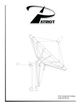
MAKE: Case IH
MODEL: Patriot
YEAR: 2010 & Newer
FIGURE 1. Case IH Patriot 3230
Note: This manual contains the installation instructions for the PowerGlide Plus and UltraGlide systems.
Be sure to identify which system you have and follow only the instructions for that system.
Preparing for Installation
Before installing AutoBoom, park the machine where the ground is level, clean, and dry. Leave the machine
turned off for the duration of the installation process.

Chapter 2
4 Case IH Patriot, Model Year 2010 & Newer AutoBoom™ Installation Manual
During the installation process, follow good safety practices. Be sure to carefully read the instructions in this
manual as you complete the installation process.
Recommendations
Raven Industries recommends the following best practices before installing or operating the AutoBoom system
for the first time, at the start of the season, or when moving the AutoBoom system to another machine:
• Ensure the machine’s hydraulic filters have been recently changed and there are no issues with the
machine’s hydraulic system (e.g., pump issues, faulty hydraulic motors, fine metal deposits in the hydraulic
hoses, etc.).
• Operate each of the machine’s boom hydraulic functions (i.e., tilt, fold, center rack, tongue extension, or
other hydraulic valve functions) three times to ensure the machine’s hydraulic valve is using fresh oil and
debris is flushed from the hydraulic hoses, valves, and filters.
• Upon installation of the AutoBoom system, operate the boom and center rack raise/lower functions through
the machine’s manual control functions first before operating them via the AutoBoom controller/field
computer to ensure the hydraulic system has been installed correctly and air is released from the system.
Raven Industries recommends the following best practices when installing the AutoBoom system.
• Use part numbers to identify the parts.
• Do not remove the plastic wrap from a part until it is necessary for installation.
• Do not remove plastic caps from a part until it is necessary for installation.
Tools Needed
The following tools are recommended for installation of the AutoBoom system:
• SAE standard-sized wrenches
• Cable ties
• Set of tools
Point of Reference
The instructions in this manual assume that you are standing behind the machine, looking toward the cab.
Hydraulic Fittings
This manual may reference the following types of hydraulic fittings:
• SAE O-ring fittings
• ORFS (O-Ring Face Seal) fittings
• JIC fittings

2
Manual No. 016-0230-095 Rev. D 5
Introduction
Updates
Software and manual updates are available on the Raven Applied Technology website:
http://www.ravenhelp.com
At Raven Industries, we strive to make your experience with our products as rewarding as
possible. One way to improve this experience is to provide us with feedback on this manual.
Your feedback will help shape the future of our product documentation and the overall service
we provide. We appreciate the opportunity to see ourselves as our customers see us and are
eager to gather ideas on how we have been helping or how we can do better.
To serve you best, please send an email with the following information to
-Case IH Patriot, Model Year 2010 & Newer AutoBoom™ Installation Manual
-Manual No. 016-0230-095 Rev. D
-Any comments or feedback (include chapter or page numbers if applicable).
-Let us know how long have you been using this or other Raven products.
We will not share your email or any information you provide with anyone else. Your feedback
is valued and extremely important to us.
Thank you for your time.
JIC fitting (M)
ORFS fitting
SAE O-ring fitting

Chapter 2
6 Case IH Patriot, Model Year 2010 & Newer AutoBoom™ Installation Manual

CHAPTER
3
Manual No. 016-0230-095 Rev. D 7
C hapter 3
PowerGlide Plus
PowerGlide Plus Kit Contents
This section contains a list of the components that are included in the PowerGlide Plus AutoBoom kit. Before
beginning the AutoBoom installation, compare the items in the AutoBoom kit with the components on this list. If
you have questions about the kit, contact your Raven dealer.
TABLE 1. PowerGlide Plus Installation Kit (P/N 117-0231-095)
Picture Item Description Part Number Qty.
Not Pictured
Manual - Case IH Patriot, Model Year 2010 &
Newer AutoBoom Installation
016-0230-095 1
Not Pictured Manual - AutoBoom Calibration & Operation 016-0130-062 1
Valve - PowerGlide Plus AutoBoom 063-0131-124 1
Plate - Hydraulic Block Mounting 107-0171-802 1
Node - PowerGlide Plus CAN AutoBoom 063-0130-010 1
Cable - PowerGlide Plus/UltraGlide 2010+
Center Rack Control CAN 20’
115-0230-073 1

Chapter 3
8 Case IH Patriot, Model Year 2010 & Newer AutoBoom™ Installation Manual
U-Bolt - 2-9/16” W x 3-1/2” L x 3/8” Thread 107-0171-616 2
Bolt - 5/16”-18 x 7/8” Hex 311-0052-104 4
Bolt - 3/8”-16 UNC x 1-1/4” Zinc Plated Hex 311-0054-106 3
Nut - 3/8”-16 Zinc Flanged Lock 312-1001-164 7
Washer - 5/16” Zinc Plated Lock 313-1000-019 4
TABLE 2. Hydraulic Kit (P/N 117-0134-075)
Picture Item Description Part Number Qty.
Fitting - 13/16” ORFS M/M/F Swivel Run Tee 333-0012-028 2
Fitting - 11/16” ORFS M/F 90° Swivel Elbow 333-0012-065 2
Fitting - 11/16” ORFS M/M/F Swivel Run Tee 333-0012-069 4
Fitting - 11/16” ORFS (M) to 9/16” SAE O-
Ring (M) Straight Adapter
333-0012-084 2
Fitting - 11/16” ORFS (M) to 3/4” SAE O-Ring
(M) 90° Elbow
333-0012-165 2
TABLE 1. PowerGlide Plus Installation Kit (P/N 117-0231-095)
Picture Item Description Part Number Qty.

3
Manual No. 016-0230-095 Rev. D 9
PowerGlide Plus
Fitting - 13/16” ORFS (M) to 3/4” SAE O-Ring
(M) Straight Adapter
333-0012-168 2
Fitting - 11/16” Hex 9/16” O-Ring Plug 333-0012-194 2
Hydraulic Hose - 13/16” ORFS (F) to 13/16”
ORFS (F) 90 ° - 36”
214-1000-311 2
Hydraulic Hose - 11/16” ORFS (F) 90° to
11/16 ORFS (F) - 44”
214-1000-494 4
TABLE 3. PowerGlide Plus Wheel Kit (P/N 117-0134-006)
Picture Item Description Part Number Qty.
Axle Assembly - Right Cushioned AutoBoom 063-0131-585 1
Axle Assembly - Left Cushioned AutoBoom 063-0131-590 1
Bracket - Left Weldment Receiver 116-0159-544 2
Bracket - Hub Retainer 107-0171-617 2
Wheel 322-0131-008 2
U-Bolt - 2-1/16” W x 3” L x 3/8” Thread 107-0171-609 4
TABLE 2. Hydraulic Kit (P/N 117-0134-075)
Picture Item Description Part Number Qty.

Chapter 3
10 Case IH Patriot, Model Year 2010 & Newer AutoBoom™ Installation Manual
U-Bolt - 1-5/16” W x 2” L x 3/8” Thread 107-0171-612 4
Bolt - 1/2”-13 x 1-1/2” SS Hex 311-0058-186 4
Nut - 1/2”-13 Zinc Plated Hex 312-1001-043 4
Nut - 3/8”-16 Zinc Flanged Lock 312-1001-164 16
TABLE 4. PowerGlide Plus Wiring Kit (P/N 117-0137-023)
Picture Item Description Part Number Qty.
Not Pictured Manual - AutoBoom Calibration & Operation 016-0130-062 1
AutoBoom Node 063-0130-010 1
Cable - Harness 115-0230-045 1
Cable - Power/CAN 115-0230-007 1
TABLE 3. PowerGlide Plus Wheel Kit (P/N 117-0134-006)
Picture Item Description Part Number Qty.

3
Manual No. 016-0230-095 Rev. D 11
PowerGlide Plus
Install the PowerGlide Plus Hydraulic System
Remove the Orifice Fittings
Before populating the hydraulic fittings on the AutoBoom valve, it is necessary to remove orifice fittings from
the valve in the PowerGlide Plus system. Failure to remove these fittings from the valve will restrict the down
speed of the booms when the system is enabled.
WARNING
The machine must remain stationary and
switched off, with the booms unfolded and
supported, during installation or maintenance.
CAUTION
When installing AutoBoom hydraulics or
performing diagnostics, maintenance, or routine
service, ensure precautions are taken to
prevent any foreign material from being
introduced into the machine’s hydraulic system.
Objects or materials that are able to bypass the
machine’s hydraulic filtration system will reduce
performance and possibly damage the
AutoBoom hydraulic valve.
NOTICE
The appearance of the AutoBoom hydraulic
valve may vary slightly from the images
contained in this manual. However, the fittings,
hose connections, and cable connections
remain the same.

Chapter 3
12 Case IH Patriot, Model Year 2010 & Newer AutoBoom™ Installation Manual
FIGURE 1. Port 3A and 3B Location
1. Locate Ports 3A and 3B on the AutoBoom valve.
FIGURE 2. Coil Removed from the AutoBoom Valve
2. Remove the coils from the solenoids near Ports 3A and 3B to gain easy access to those ports.
FIGURE 3. Port Plugs Removed from the AutoBoom Valve
3. Use an Allen wrench to remove the plugs from Ports 3A and 3B.
Port 3B
Port 3A

3
Manual No. 016-0230-095 Rev. D 13
PowerGlide Plus
FIGURE 4. Orifice Fitting Removed from the AutoBoom Valve
4. Remove the orifice fittings from Ports 3A and 3B.
Important: Tip the AutoBoom valve on its side and use the Allen wrench to remove the orifice from the cavity,
taking care not to let the fitting fall into the valve.
FIGURE 5. Port Plug Reinstalled on the AutoBoom Valve
5. Use the Allen wrench to reinstall the port plugs on Ports 3A and 3B of the AutoBoom valve.
FIGURE 6. Coil Reinstalled on the AutoBoom Valve
6. Reinstall the coils on the solenoids of the AutoBoom valve.
Orifice Fitting
Removed - Keep for
Future Use

Chapter 3
14 Case IH Patriot, Model Year 2010 & Newer AutoBoom™ Installation Manual
Install the Fittings on the AutoBoom Valve
Before mounting the AutoBoom valve on the machine, install the fittings in the appropriate ports of the
AutoBoom valve. This prepares the valve for installation and simplifies the hose connection process later in the
procedure. Refer to the following table to install the fittings.
Mount the AutoBoom Valve
FIGURE 7. AutoBoom Valve Mounted on the Valve Mounting Plate
1. Secure the AutoBoom valve (P/N 063-0131-124) to the mounting plate (P/N 107-0171-802) using four
5/16” hex bolts (P/N 311-0052-104) and four 5/16” lock washers (P/N 313-1000-019).
FIGURE 8. AutoBoom Valve Mounted on the Machine
Fitting Part Number Port
Fitting - 11/16” ORFS (M) to 3/4” SAE O-Ring (M) 90° Elbow 333-0012-165
LF CYL RTN,
R T C Y L R T N
Fitting - 11/16” ORFS (M) to 9/16” SAE O-Ring (M) Straight Adapter 333-0012-084 LC, RC
Fitting - 13/16” ORFS (M) to 3/4” SAE O-Ring (M) Straight Adapter 333-0012-168 P, T
Fitting - 11/16” Hex 9/16” SAE O-Ring Plug 333-0012-194 LV, RV

3
Manual No. 016-0230-095 Rev. D 15
PowerGlide Plus
2. Secure the mounting pate to the machine’s center rack using two 2-9/16” W x 3-1/2” L x 3/8” thread U-bolts
(P/N 107-0171-616) and four 3/8”-16 zinc flanged lock nuts (P/N 312-1001-164).
Note: Mount the valve so that Port P faces up and Ports LC and RC face the center of the machine.
Install the Pressure and Tank Hoses
FIGURE 9. Pressure and Tank Hoses Installed
1. Disconnect the machine’s pressure hose from the machine’s hydraulic valve.
2. Install a 13/16” ORFS M/M/F swivel run tee fitting (P/N 333-0012-028) in the machine’s pressure port.
3. Attach the machine’s pressure hose to the opposite end of the installed tee fitting.
4. Connect the 90° end of the supplied hydraulic hose (P/N 214-1000-311) to the 90° end of the tee fitting.
5. Connect the straight end of the installed hydraulic hose to Port P of on the AutoBoom valve.
6. Disconnect the machine’s tank hose from the machine’s hydraulic valve.
WARNING
Hydraulics are under pressure. Care should
always be taken with a system that has been
pressurized. When disconnecting or purging
hydraulic hoses, be aware that the hydraulic
fluid within the machine’s system may be
extremely hot and under high pressure.
CAUTION
When installing AutoBoom hydraulics or
performing diagnostics, maintenance, or routine
service, ensure precautions are taken to
prevent any foreign material or contaminants
from being introduced into the machine’s
hydraulic system.
Objects or materials that are able to bypass the
machine’s hydraulic filtration system will reduce
performance and possibly damage the
AutoBoom hydraulic valve.

Chapter 3
16 Case IH Patriot, Model Year 2010 & Newer AutoBoom™ Installation Manual
7. Install a 13/16” ORFS M/M/F swivel run tee fitting (P/N 333-0012-028) in the machine’s tank port.
8. Attach the machine’s tank line to the opposite end of the installed tee fitting.
9. Connect the 90° end of the supplied hydraulic hose (P/N 214-1000-311) to the 90° end of the tee fitting.
10. Connect the straight end of the installed hydraulic hose to Port T on the Autoboom valve.
Install the Left and Right Cylinder Hoses
FIGURE 10. Left and Right Cylinder Hoses Installed
1. Trace the machine’s cylinder hoses from the rod-end of the tilt cylinders to the machine’s hydraulic valve.
2. Disconnect the machine’s left and right tilt cylinder hoses from the machine’s hydraulic valve.
3. Install 11/16” ORFS M/M/F swivel run tee adapter fittings (P/N 333-0012-069) in the open cylinder ports of
the machine’s hydraulic valve.
4. Connect the machine’s right cylinder hose to the opposite end of the tee fitting installed in the right cylinder
port.
5. Install the 90° end of the supplied hydraulic hose (P/N 214-1000-494) on the 90° end of the installed tee
fitting.
6. Connect the straight end of the installed hydraulic hose to the fittings installed in Port RC of the AutoBoom
valve.
7. Connect the machine’s left cylinder hose to the opposite end of the tee fitting installed in the left cylinder
port.
8. Install the 90° end of the supplied hydraulic hose (P/N 214-1000-494) on the 90° end of the installed tee
fitting.
9. Connect the straight end of the installed hydraulic hose to the fittings installed in Port LC of the AutoBoom
valve.
/