Page is loading ...

kit articolata
iStrUZioNi Di MoNtaGGio - aSSeMbly iNStrUctioNS
iNStrUctioNS De MoNtaGe - iNStrUccioNeS De MoNtaje
MoNtaGeaNleitUNG - MoNtaGe-iNStrUctieS

KIT ARTICOLATA
ENGLISH
Guide for the installer
Pagina 7
Thank you for choosing our product. We are sure you will get
the performances you expect to satisfy your requirements.
All our products are the result of a many years’ experience
in the field of the automated systems.
The ARTICULATION KIT enables you to install barriers also in
garage driveways where the very small distance between
floor and ceiling prevents you from installing a barrier with
a traditional rod.
With the articulation kit no further accessory can be
fitted on the rod. You can only use the fixed support
on the end
Refer to the following instructions for the kit assembly:
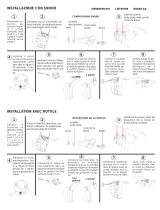
PreParing the housing
Place the cardboard template, fig. 1 ref a, on the
barrier housing observing the orientation in fig. 1. The
central hole of the template must be inserted on the
transmission shaft, fig. 1 ref. b.
Align the template in such a way that both holes on
the bottom of the template match both plastic plugs,
fig. 1 ref. c, on the housing.
According to the left-hand or right-hand direction of the
beam with respect to the housing, mark the four holes,
respectively ref. d or e in figure 1, on the top of the
template, over the drawing showing the application.
Use a Ø 4.5 mm bit to drill the housing in the just
determined location.
Secure the pin, fig. 2 ref. a, in the holes just made using
the four supplied screws, fig. 2 ref. b.
The supplied screws are self-drilling screws, therefore no
threading on the holes is required.
Fit the plastic bushing, fig. 3 ref. a, on the just secured
pin and secure it with the relevant Seeger ring, fig. 3
ref. b.
Insert the metal rope end already closed in the
fastening bracket, fig. 4.
Fit the bracket into the plastic bushing and screw both
supplied M6 nuts, fig. 4.
We recommend you to screw the nuts up to the half of
the bracket threaded section. In this way, the metal
rope tension can be later adjusted.
PreParing and mounting the rod
In the following instructions, "Section I" refers to the rod
section that is fixed to the barrier housing, whereas
"Section II II" refers to the other rod section.
Determine the length of both rod sections according
to the length limits shown in fig. 5 and to the passage
to cover.
Cut both rod sections according to the determined
length; also cut the upper red profile and the lower
rubber edge.
Remove both the rubber edge and the red profile from
both rod sections.
On section I, from the part opposite to the rod centering
hole on the housing, insert the upper fastening cylinder,
fig. 6 ref. a, into the rod circular cavity, Fig. 6 ref. b, until
it matches the rod edge, see fig. 6. The long side of the
fastening cylinder must be directed as shown in fig. 6.
Use the fastening cylinder as a template and drill the
two Ø 6 mm holes.
Repeat the same operation with the other rod cavity,
fig. 6 ref. c.
Repeat the operations on section II, on one side only.
At the end of these operations, both rod sections have,
on one end, four Ø 6 mm holes that will be later used
to secure the joint unit.
With reference to figure 7 insert, into section I, the upper
fastening cylinder, ref. a, the lower fastening cylinder,
1.
2.
3.
4.
5.
6.
7.
8.
1.
2.
3.
4.
5.
6.
7.
8.
9.
ref. b, and the joint unit, ref. c, observing the orientation
shown in fig. 7.
Secure the whole part using the supplied screws M
6x75, ref. d.
Place again the red profile and the rubber edge on
section I, then fit the rod as indicated in the barrier
instructions.
Fit the upper and lower fastening cylinder, fig. 8 ref. a
and b, in section II of the rod, fig. 8 ref. c.
Fit section II on the joint unit and secure the whole part
with both M 6x75 screws, fig. 8 ref. d.
Secure the rope fastening pin on the joint unit, fig. 9
ref. a, using the supplied blind nut, fig. 9 ref. b. For a
correct operation, the pin must face the barrier housing,
see fig. 9A and 9B.
Assemble the plastic bushing as shown in fig. 10 fitting
the metal ring for the rope, ref. a, on the bracket,
ref. a.
We recommend you to tighten the nuts until the
threaded part of the ring is flush with them. In this
way you will be later able to adjust the metal rope
tension and therefore the alignment of both rod
sections.
Fit the plastic bushing on the pin and secure the whole
part using the relevant Seeger ring, see fig. 11.
Wrap the free end of the metal rope on the metal
ring, fig. 12.
Align both rod sections and secure the metal rope using
both supplied clamps, fig. 13.
To ensure a correct fastening of the metal rope, remove,
in the securing area, the plastic sheath from the
metal rope and position both clamps 180° with
respect to each other, see fig. 13.
Prepare the barrier for manual operation, see relevant
instructions. Move the rod by hand and check if, when
the rod is closed, both sections remain aligned.
If necessary, adjust the rope tension using the nuts that
secure the metal brackets (Fig. 10 ref. b) until both rod
sections are perfectly aligned.
Cut the metal rope in excess.
Place again the red profile and the rubber edge on
section II.
Fit the covering plug on the end of section II observing
the barrier instructions.
Complete the rod installation following the instructions
on the barrier manual.
Then fit the balancing spring according to the
instructions on the barrier manual.
10.
11.
12.
13.
14.
15.
16.
17.
18.
19.
20.
21.
22.
23.
24.
25.
/