Page is loading ...

7
4247530-Rev A 7-1
Chapter 7
Steering
Specifications . . . . . . . . . . . . . . . . . . . . . . . . . . . . . . . . . . . . . . . . . . . . . . . . . . . . . . . . . . . . . . . . . 7-2
Component Location . . . . . . . . . . . . . . . . . . . . . . . . . . . . . . . . . . . . . . . . . . . . . . . . . . . . . . . . . . . 7-3
Checks and Adjustments . . . . . . . . . . . . . . . . . . . . . . . . . . . . . . . . . . . . . . . . . . . . . . . . . . . . . . . 7-4
Steering Cable Adjustment . . . . . . . . . . . . . . . . . . . . . . . . . . . . . . . . . . . . . . . . . . . . . . . . . . 7-4
Repair . . . . . . . . . . . . . . . . . . . . . . . . . . . . . . . . . . . . . . . . . . . . . . . . . . . . . . . . . . . . . . . . . . . . . . . 7-4
Steering Wheel (Manual Steering) . . . . . . . . . . . . . . . . . . . . . . . . . . . . . . . . . . . . . . . . . . . . 7-4
Steering Wheel (Power Steering) . . . . . . . . . . . . . . . . . . . . . . . . . . . . . . . . . . . . . . . . . . . . . 7-5
Steering Unit (PN 4196484) . . . . . . . . . . . . . . . . . . . . . . . . . . . . . . . . . . . . . . . . . . . . . . . . . 7-5
Steering Unit (PN 4136214) . . . . . . . . . . . . . . . . . . . . . . . . . . . . . . . . . . . . . . . . . . . . . . . . 7-13
Steering Tower Cover . . . . . . . . . . . . . . . . . . . . . . . . . . . . . . . . . . . . . . . . . . . . . . . . . . . . . 7-21
Steering Cylinder . . . . . . . . . . . . . . . . . . . . . . . . . . . . . . . . . . . . . . . . . . . . . . . . . . . . . . . . . 7-23
Steering Fork (Manual Steering) . . . . . . . . . . . . . . . . . . . . . . . . . . . . . . . . . . . . . . . . . . . . . 7-25
Steering Fork (Power Steering) . . . . . . . . . . . . . . . . . . . . . . . . . . . . . . . . . . . . . . . . . . . . . . 7-26

7-2 4247530-Rev A
STEERING
7
Specifications
Checks and Adjustments Specifications
Steering Cable Deflection in. (mm) 0.500–0.625 (12.7–15.8) with 3–5 lb
(13.3–22.2 N) of pull
Repair Specifications
Steering Wheel Nut Torque lb-ft (N·m) 25–30 (34–41)
Steering Unit (PN 4196484) Special Screws Torque
lb-ft (N·m) 20–24 (27–33)
Steering Unit (PN 4136214) Special Bolt Nut Torque
lb-ft (N·m) 20–24 (27–33)
Steering Unit Hydraulic Hoses Torque
lb-ft (N·m) 25 (34)
Steering Cylinder Ball Joint Center-to-Center Distance
in. (mm) 15.875 ± 0.060 (403 ± 1.5)
Steering Fork Jam Nut (Manual Steering) Torque
lb-ft (N·m) 55 ± 5 (74.5 ± 6.8)
Steering Fork Jam Nut (Power Steering) End Play
in. (mm) 0.001–0.008 (0.025–0.203)


7-4 4247530-Rev A
STEERING
7
Checks and Adjustments
Steering Cable Adjustment
See Figure 7-2.
1. Park the mower safely. (See “Park Mower Safely” on
page 1-6.)
2. Remove front seat skirt. (See “Front Seat Skirt” on
page 9-16.)
3. Remove fuel tank. (See “Fuel Tank (Gasoline)” on
page 9-8.)
Figure 7-2
4. Raise and support rear of machine with jackstands.
5. Position rear steering pulley (2) straight and neutral.
6. Adjust nuts (1) at cable ends until deflection at
midpoint (3) is 0.500–0.625 in. (12.7–15.8 mm) with
3–5 lb (13.3–22.2 N) of pull.
Repair
Steering Wheel (Manual Steering)
Removal and Installation
See Figure 7-3.
1. Park the mower safely. (See “Park Mower Safely” on
page 1-6.)
Figure 7-3
2. Remove nuts (5), lock washers (4), washers (3), and
screws (2).
3. Remove steering wheel (1) from steering column (6).
Installation Notes
• Install steering wheel by reversing the order of
removal.
• Adjust steering wheel angle prior to tightening
hardware.
TN3378
3
1
1
3
2
TN3407
3
1
2
5
4
3
6

STEERING
4247530-Rev A 7-5
7
Steering Wheel (Power Steering)
Removal and Installation
See Figure 7-4.
1. Park the mower safely. (See “Park Mower Safely” on
page 1-6.)
Figure 7-4
2. Remove (unsnap) cap (1) from steering wheel (4).
3. Remove nut (2) and internal-tooth lock washer (3).
4. Remove steering wheel (4) and four washers (5)
from steering column (6).
Installation Notes
• Install steering wheel by reversing the order of
removal.
• Tighten the steering wheel nut (2) to 25–30 lb-ft (34–
41 N·m).
Steering Unit (PN 4196484)
Removal and Installation
See Figures 7-5 and 7-6.
1. Park the mower safely. (See “Park Mower Safely” on
page 1-6.)
2. Remove steering wheel. (See “Steering Wheel
(Power Steering)” on page 7-5.)
3. Remove steering tower cover. (See “Steering Tower
Cover” on page 7-21.)
Figure 7-5
4. Remove four screws (2) and lock washers (3), and
remove steering column (1) from steering unit (4).
TN2969
TN2969
3
2
6
1
4
5
TN3780
1
2 3
4

7-6 4247530-Rev A
STEERING
7
Figure 7-6
NOTES
• Label all hydraulic hoses and record their locations to
ensure correct installation.
• Plug hydraulic hoses after disconnecting to prevent
loss of hydraulic oil.
5. Disconnect hydraulic hose (5) from steering unit port
“L.”
6. Disconnect hydraulic hose (6) from steering unit port
“R.”
7. Disconnect hydraulic hose (7) from steering unit port
“T.”
• Disconnect hydraulic hose (8) from steering unit port
“P.”
8. Remove steering unit (4).
Installation Notes
• Install steering unit by reversing the order of removal.
• Tighten hydraulic hoses to 25 lb-ft (34 N·m).
• Check hydraulic oil level. Add oil as needed.
• Start the machine and check for hydraulic leaks and
cylinder operation. Repair as necessary.
Steering Unit (PN 4196484) Service Fixture
See Figures 7-7 and 7-8.
Figure 7-7: Steering Unit Service Fixture
NOTICE
E
TN2148
8
5
6
7
Required Tools or Equipment
Steering Unit Service Fixture
1 0.165 in. (4.2 mm) 6 2.0 in. (50.8 mm)
2 0.250 in. (6.35 mm) Ø Hole (4) 7 4.0 in. (101.5 mm)
3 2.280 in. (58.0 mm) Ø 8 1.5 in. (38.1 mm) Ø Hole
48.0 in. (202 mm) 945° (4)
5 2.0 in. (50.8 mm)
Do not clamp the steering unit directly into a vise.
Clamping the steering unit directly into a vise
may damage or distort the steering unit.
TN2142
1
5
3
2
6
7
8
4
9

STEERING
4247530-Rev A 7-7
7
Figure 7-8
1. Place the steering unit service fixture (11) securely in
a vise.
2. Place the steering unit (10) into the service fixture
(11), input shaft down.
3. Secure the steering unit to the service fixture using
four M6-1 x 20 mm screws and M6 lock washers (12
and 13).
TN2143
TN2143
10
11
1312

7-8 4247530-Rev A
STEERING
7
Disassembly
See Figures 7-9 and 7-10.
Figure 7-9
1 Special Screw (4) 8 Gearwheel Rim 15 Spring Retaining Ring 22 Ball Stop
2 Special Screw (1) 9 Distributor Plate 16 Spool 23 Emergency Steering Ball
3 O-Ring (5) 10 Cardan Shaft 17 Thick Bearing Race 24 Housing
4 End Cover 11 O-Ring 18 Bearing 25 Name Plate
5 Spacer 12 Sleeve 19 Thin Bearing Race 26 Steering Relief Valve
6 O-Ring (2) 13 Cross Pin 20 Shaft Seal 27 Steering Relief Valve Spring
7 Gearwheel 14 Spring Set 21 Check Valve Ball
R
L
P
T
TN4344
1
3
4
5
6
8
6
9
10
11
12
13
14
15
16
17
18
23
20
21
22
24
25
26
27
7
19
2

STEERING
4247530-Rev A 7-9
7
!
CAUTION
NOTES
• Before attempting repairs or disassembly of any
hydraulic components, thoroughly clean the
components and work area. A clean work area is
essential to satisfactory operation of repaired
hydraulic components.
• Utilize steering unit service fixture for disassembly.
(See “Steering Unit (PN 4196484) Service Fixture”
on page 7-6.)
1. Scribe a line from port “P” to bottom of steering unit.
This line can be used to determine port “P” with end
cover removed and for proper orientation of sections
for assembly.
2. Remove four special screws (1), one special screw
(2), and five O-rings (3).
3. Remove end cover (4) by sliding it off to the side.
4. Remove cardan shaft spacer (5).
5. Hold a hand under the gearwheel rim (8) and
gearwheel (7) to keep the gearwheel from falling out,
and remove the gearwheel rim (8), gearwheel (7),
and two O-rings (6).
6. Remove cardan shaft (10).
7. Remove distributor plate (9).
8. Remove O-ring (11) from housing (24).
9. Remove spool assembly.
10. Remove thin bearing race (19), bearing (18), and
thick bearing race (17).
11. Remove shaft seal (20).
12. Remove spring retaining ring (15).
13. Carefully press cross pin (13) out of the spool (16)
and sleeve (12), and remove spool from sleeve.
14. Press spring set (14) out of spool (16).
15. Remove fixture from vise and shake out check valve
ball (21), emergency steering ball (23), and ball stop
(22). Re-secure service fixture in vise with input shaft
down.
16. Remove housing (24) from service fixture.
17. Remove steering relief valve (26) and steering relief
valve spring (27).
Figure 7-10
Wear eye protection when assembling and
disassembling the steering unit. Springs and
other objects may be propelled into the air,
causing eye injury.
R
L
P
T
TN4345
1
Steps 1-3
Scribe line
aligned with
port “P.”
Steps 4-5
Steps 6-8 Steps 9-11
Steps 12-14 Step 15
Step 17
Spool
Assembly
Included in Seal Kit
3
4
5
7
8
6
10
9
11
24
17
18
19
20
24
13
16
12
15
14
21
22
23
24
26
27
24
2

7-10 4247530-Rev A
STEERING
7
Assembly
See Figures 7-11 through 7-13.
Figure 7-11
1 Special Screw (4) 8 Gearwheel Rim 15 Spring Retaining Ring 22 Ball Stop
2 Special Screw (1) 9 Distributor Plate 16 Spool 23 Emergency Steering Ball
3 O-Ring (5) 10 Cardan Shaft 17 Thick Bearing Race 24 Housing
4 End Cover 11 O-Ring 18 Bearing 25 Name Plate
5 Spacer 12 Sleeve 19 Thin Bearing Race 26 Steering Relief Valve
6 O-Ring (2) 13 Cross Pin 20 Shaft Seal 27 Steering Relief Valve Spring
7 Gearwheel 14 Spring Set 21 Check Valve Ball
R
L
P
T
TN4344
1
3
4
5
6
8
6
9
10
11
12
13
14
15
16
17
18
23
20
21
22
24
25
26
27
7
19
2

STEERING
4247530-Rev A 7-11
7
!
CAUTION
NOTES
• Inspect all parts for wear or damage and replace as
necessary.
• Lubricate all parts with clean hydraulic oil before
assembly.
• Always install new O-rings for assembly; used parts
may leak.
• Utilize steering unit service fixture for assembly. (See
“Steering Unit (PN 4196484) Service Fixture” on
page 7-6.)
• Letter references (A-C) refer to components of Sauer
Danfoss Shaft Seal Tool.
1. Assemble relief valve (26 and 27) to housing (24).
Use new check valve o-ring included in seal kit.
2. Assemble shaft seal (20) onto guide (A).
3. Insert outer sleeve (B) into housing (24).
4. Place guide (A) on end of guide tool (C). Lubricate
shaft seal and O-ring.
5. Slide guide tool (C) into outer sleeve (B) and press
shaft seal into position. Remove outer sleeve and
guide tool. Guide (A) should remain inside housing
after seal is installed.
6. Install thin bearing race (19), bearing (18), and thick
bearing race (17) into housing (24).
7. Slide spool (16) into sleeve (12) and align so that
cross pin slots are adjacent to each other.
8. Center the spring set (14) in the spool and sleeve
assembly, and install spring retaining ring (15).
NOTES
• When installing spring set, insert the curved springs
between the flat springs and push in place.
• Spring retaining ring (15) must be able to rotate
unimpeded by the springs.
9. Press cross pin (13) in the spool and sleeve
assembly.
10. While holding the cross pin in place, guide the spool
and sleeve assembly into housing (23). When
installed, cross pin (12) must point towards port “P.”
Spool will push seal guide (A) out of housing as it is
installed.
Figure 7-12
Wear eye protection when assembling and
disassembling the steering unit. Springs and
other objects may be propelled into the air,
causing eye injury.
Required Tools and Materials
Seal Kit (Jacobsen PN 4197940)
Shaft Seal Tool (Sauer Danfoss SJ150L4011-01)
TN4341
Step 1
Included in Seal Kit
Step 2
Steps 3-5
Step 6 Steps 7-9
Step 10
26
27
24
20
A
A
B
C
24
17
18
19
24
12
13
16
14
15
24
Spool
Assembly
Cross
Pin
L
R
P
T
E

7-12 4247530-Rev A
STEERING
7
11. Place emergency steering ball (23) in port “P.”
12. Place ball stop (22) in port “P.”
13. Place check valve ball (21) in port “P.”
14. Install O-ring (11) in housing (24).
15. Place distributor plate (9) on housing (24) and align
scribe line and mounting holes.
16. Assemble cardan shaft (10) to spool (16) ensuring
cardan shaft engages with cross pin (13).
17. Place gearwheel (7) over the distributor plate (9).
NOTE
See step 16 in Figure 7-13. When installing the
gearwheel, the gearwheel must be correctly aligned so
that it engages with the cardan shaft. The cross pin (13)
in the spool assembly must line up with the bottom of the
spline in the gearwheel (7).
18. Install O-rings (6) into groove on each side of the
gearwheel rim.
19. Place gearwheel rim (8) over the distributor plate (9)
and gearwheel (7). Align scribe line and mounting
holes.
20. Install spacer (5) over the cardan shaft (10).
NOTES
• Place end cover so that the hole marked “P” lines up
with port “P” in the housing.
• Special screw (2) (with no oil flow connection) must
be fitted in port “E.”
21. Using scribe line, align end cover (4) to housing (24).
Install special screws (1) with O-rings (3) into ports
“T,” “P,” “L,” and “R.” Install special screw (2) with
O-ring (3) into port “E.” Tighten screws in an
alternating pattern to 20–24 lb-ft (27–33 N·m).
22. Remove the steering unit from the service fixture.
23. Assemble steering unit into mower.
NOTE
Do not tighten steering column mounting hardware until
steering relief pressure has been set. Column must be
removed when adjusting relief valve.
24. Set steering unit relief pressure. (See “Steering
Relief Valve Adjustment” on page 6-52.)
!
WARNING
Figure 7-13
Keep hands and arms clear of steering wheel on
initial startup of engine. Steering unit can
become a hydraulic motor if step 17 is not
correctly performed.
R
L
P
T
TN4342
21
22
23
24
Steps 11-13 Steps 14-16
Step 16
Steps 17-20 Step 21
10
9
11
24
5
6
7
9
Cross
Pin
Spline
Bottoms
8
1
3
4
Scribe line
aligned with
port “P.”
Included in Seal Kit
L
P
R
E
T
Port
“P”
2

STEERING
4247530-Rev A 7-13
7
Steering Unit (PN 4136214)
Removal and Installation
See Figures 7-14 and 7-15.
1. Park the mower safely. (See “Park Mower Safely” on
page 1-6.)
2. Remove steering wheel. (See “Steering Wheel
(Power Steering)” on page 7-5.)
3. Remove steering tower cover. (See “Steering Tower
Cover” on page 7-21.)
Figure 7-14
NOTES
• Label all hydraulic hoses and record their locations to
ensure correct installation.
• Plug hydraulic hoses after disconnecting to prevent
loss of hydraulic oil.
4. Disconnect hydraulic hose (1) from steering unit port
“In.”
5. Disconnect hydraulic hose (2) from steering unit port
“RT.”
6. Disconnect hydraulic hose (3) from steering unit port
“LT.”
7. Disconnect hydraulic hose (4) from steering unit port
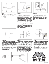
“Out.”
Figure 7-15
8. Support the steering unit (7).
9. Remove four lock nuts (5) and flat washers (8).
10. Remove steering unit (7) from bracket (6).
Installation Notes
• Install steering unit by reversing the order of removal.
• Tighten hydraulic hoses to 25 lb-ft (34 N·m).
• Check hydraulic oil level. Add oil as needed.
• Start the machine and check for hydraulic leaks and
cylinder operation. Repair as necessary.
TN1389A
3
4
1
2
5
6
7
8

7-14 4247530-Rev A
STEERING
7
Steering Unit (PN 4136214) Service Fixture
See Figures 7-16 and 7-17.
Figure 7-16
NOTICE
Figure 7-17
1. Place the steering unit service fixture (2) securely in
a vise.
2. Place the steering unit (1) into the service fixture (2),
input shaft down.
3. Secure the steering unit to the service fixture using
four nuts (3).
IMPORTANT
Scribe a line from the top to the bottom of the
steering unit assembly, not including the steering
tube. Use the scribed line for reference when
assembling the valve sections.
Required Tools or Equipment
Steering Unit Service Fixture
Do not clamp the steering unit assembly directly
into a vise. Clamping the steering unit directly
into a vise may damage or distort the steering
unit.
TN1435
TN1437
3
1
2

STEERING
4247530-Rev A 7-15
7
Disassembly
See Figure 7-18.
Figure 7-18
1Nut
2Port Cover
3 Relief Valve Assembly
4 Seal Ring
5 Ball 9/32 inch
6O-Ring (4)
7Port Manifold
8Alignment Pin
9Spring
10 Seal Ring
11 Valve Ring (Matched Set)
12 Valve Plate (Matched Set)
13 Spring
14 Seal Ring
15 Hex Drive Assembly
16 Isolation Manifold
17 Alignment Pin
18 Drive Link
19 Seal Ring
20 Metering Ring
21 Seal Ring
22 Socket Head Cap Screw (11)
23 Commutator Seal
24 Commutator Cover
25 Commutator Ring
26 Commutator
27 Alignment Pin
28 Drive Link Spacer
29 Rotor
30 Stator
31 Drive Plate
32 Spacer
33 Thrust Bearing
34 Face Seal
35 Seal Spacer
36 Upper Cover Plate
37 Retaining Ring
38 Steering Shaft
39 Steering Tube
40 Bearing
41 Seal
42 Shaft Nut
43 Special Bolt
3
1
11
10
9
8
7
6
5
4
2
17
16
15
14
13
12
29
28
27
26
25
24
23
22
21
20
19
18
33
32
31
30
36
34
35
37
38
39
40
41
42
43
TN1428

7-16 4247530-Rev A
STEERING
7
!
CAUTION
NOTE
Before attempting repairs or disassembly of any
hydraulic components, thoroughly clean the components
and work area. A clean work area is essential to
satisfactory operation of repaired hydraulic components.
1. Remove nuts (1) and port cover (2).
2. Remove relief valve (3) from the port cover (2).
3. Carefully remove the port manifold (7). Be prepared
to catch the three springs (9). Remove the springs.
4. Remove the valve ring (11), valve plate springs (13),
and valve plate (12).
5. Remove the hex drive (15) and isolation manifold
(16).
NOTE
Secure the alignments pins (17) to prevent loss.
6. Remove the drive link (18) and metering ring (20).
7. Remove the metering package (24–31) and
commutator seal (23). The metering package is
serviced as an assembly kit. Refer to the Parts &
Maintenance Manual.
NOTE
The metering package should be disassembled for
inspection purposes only. Proceed with step 8 for
disassembly and inspection procedures. If you are not
disassembling the metering package, proceed to step 11.
8. Remove the socket head cap screws (22),
commutator cover (24), commutator ring (25), and
commutator (26).
9. Remove the five alignment pins (27).
10. Remove the drive link spacer (28), rotor (29), and
stator (30) from the drive plate (31).
11. Remove the face seal (34) and seal spacer (35).
12. Remove the thrust bearing (33) and spacer (32).
13. Remove the upper cover plate (36) and retaining ring
(37).
14. Remove the special bolts (43).
15. Remove the steering shaft (38) out of tube (39).
16. Remove the bearing (40) and seal (41).
Wear eye protection when assembling and
disassembling the steering unit. Springs and
other objects may be propelled into the air
causing eye injury.

STEERING
4247530-Rev A 7-17
7
Inspection
See Figures 7-19 and 7-20.
Figure 7-19
1Nut
2Port Cover
3 Relief Valve Assembly
4 Seal Ring
5 Ball 9/32 inch
6 O-Ring (4)
7 Port Manifold
8 Alignment Pin
9Spring
10 Seal Ring
11 Valve Ring (Matched Set)
12 Valve Plate (Matched Set)
13 Spring
14 Seal Ring
15 Hex Drive Assembly
16 Isolation Manifold
17 Alignment Pin
18 Drive Link
19 Seal Ring
20 Metering Ring
21 Seal Ring
22 Socket Head Cap Screw (11)
23 Commutator Seal
24 Commutator Cover
25 Commutator Ring
26 Commutator
27 Alignment Pin
28 Drive Link Spacer
29 Rotor
30 Stator
31 Drive Plate
32 Spacer
33 Thrust Bearing
34 Face Seal
35 Seal Spacer
36 Upper Cover Plate
37 Retaining Ring
38 Steering Shaft
39 Steering Tube
40 Bearing
41 Seal
42 Shaft Nut
43 Special Bolt
TN1428
28
29
30
31
32
33
34
35
36
37
38
39
40
41
42
43
12
13
14
15
16
17
3
18
19
20
21
22
23
24
25
26
27
6
7
8
9
10
11
1
2
4
5

7-18 4247530-Rev A
STEERING
7
IMPORTANT
Always replace springs as a set.
1. Inspect the springs (9 and 13) for bent, broken, or
distorted coils.
2. Inspect the finished ground surfaces of all the
components.
3. Inspect the slot edges and surface for nicks, scoring,
and rounding edges.
NOTE
The valve ring (11) and valve plate (12) are a matched
set and are not serviceable.
4. Inspect the hex drive (15) for wear.
5. Inspect the isolation manifold (16) for nicks,
scratches, and scoring. A polished wear pattern due
to valve plate rotation is normal.
6. Inspect the drive link (18) for wear and damage.
7. Inspect the thrust bearing (33) for dents, spalling,
and missing rollers.
8. Discard all seals and seal rings.
9. Inspect the commutator cover (24) and drive plate
(31) for wear and damage. A polished wear pattern is
normal.
Figure 7-20
10. Inspect the rotor (45) and stator (46) fit for wear and
damage.
11. Install rotor in stator and center the rotor lobe (47)
across from a lobe to be measured (44). Measure
rotor (45) and stator (46) fit for maximum trip
clearance of 0.003 in. (0.08 mm).
Assembly
See Figures 7-21 through 7-24.
45
46
44
47
TN3850
Service Part Kits
Seal Kit (Jacobsen P/N 557738)
Metering Assembly Kit (Jacobsen P/N 5003220)
Spring Kit (Jacobsen P/N 502924)
Jacket Tube Kit (Jacobsen P/N 5003219)
Needle Roller Kit (Jacobsen P/N 502925)

STEERING
4247530-Rev A 7-19
7
Figure 7-21
NOTE
In the following assembly steps, it is important to align
the components for proper operation of the steering unit.
Use the scribed line for reference when assembling the
valve sections.
1. Install a new bearing (32) and seal (33) in the
steering tube (31). Crimp the tube end in two places,
90° apart.
2. Place the steering tube (31) and special bolts (28) in
the service fixture.
3. Install the retaining ring (29) on the steering shaft
(30) and install into steering tube (31).
4. Install the upper cover plate (27).
5. Assemble the seal spacer (26) and face seal (25).
6. Grease the upper cover plate (27) and install the
assembled seal, backup ring, and seal spacer.
1 Nut 10 Spring (3) 19 Metering Ring 27 Upper Cover Plate
2 Port Cover 11 Valve Plate (Matched Set) 20 Seal Ring 28 Special Bolt
3 Relief Valve Assembly 12 Seal Ring 21 Commutator Seal 29 Retaining Ring
4 O- Ring (4) 13 Hex Drive Assembly 22 Metering Package 30 Steering Shaft
5 Seal Ring 14 Alignment Pin 23 Spacer 31 Steering Tube
6 Port Manifold 15 Isolation Manifold 24 Thrust Bearing 32 Bearing
7 Spring (3) 16 Alignment Pin 25 Face Seal 33 Seal
8 Seal Ring 17 Seal Ring 26 Seal Spacer 34 Shaft Nut
9 Valve Ring (Matched Set) 18 Drive Link
TN1439
16
8
7
6
5
3
2
1
21
22
23
24
25
26
27
28
29
30
31
32
33
34
10
12
11
9
14
13
15
17
18
19
20
4

7-20 4247530-Rev A
STEERING
7
NOTE
If the metering package was disassembled, proceed with
step 7. If the metering package was not disassembled or
a new one is being installed, proceed with step 19.
Figure 7-22
7. Place the drive plate (52) on a flat lint, free surface.
8. Place the stator (51) on the drive plate (52) and insert
the rotor (50) into the stator.
9. Apply a small amount of grease to the drive link
spacer (49) and install in the rotor (50).
10. Place the commutator (47) on top of the rotor (50)
with the aligning pin holes facing up. Place a few
drops of oil in each recess of the commutator (47).
NOTE
Make sure the pins (48) are pressed below the surface of
the commutator (47).
11. Align the five pin holes in the commutator (47) with
the holes in the rotor (50) and install the five pins
(48).
12. Install the commutator ring (46) and commutator
cover (45), flat surface down with ring screw
recesses, stator screw slots, and cover screw holes
aligned. Install the 11 socket head cap screws (44).
NOTE
Do not tighten the cap screws.
13. Place the metering ring (19) on a hard flat, surface.
14. Place the assembled metering package in the center
of the metering ring (19) with the commutator cover
down.
15. Place a 0.007 in. (0.18 mm) shim stock, 0.5 in. (13
mm) wide by 1.5 in. (38 mm) long, in three places,
equal distance apart, between the metering ring and
metering package.
Figure 7-23: Metering Package Torque Sequence
16. Tighten the capscrews (44) twice in sequence to
11–13 lb-in. (1.2–1.5 N·m).
17. Remove the metering package and shims. Place the
drive link (18) large tang into the rotor. Turn the
metering package by hand to make sure there is no
binding.
NOTE
The metering package should rotate inside the stator. If
binding occurs, disassemble the metering package,
correct the cause, and repeat the assembly process.
18. Place the metering ring (19) on top of the upper
cover plate (27) with the alignment pin holes up.
19. Lubricate and install the thrust bearing spacer (23)
and thrust bearing (24) into the metering ring (19).
20. Place the metering package (22) into the metering
ring (19), engaging the drive slot with the steering
shaft.
21. Install the commutator seal (21), seal ring (20), and
drive link (18).
22. Place the isolation manifold (15) on the metering ring
(19) with the alignment pin holes up. Install the
alignment pins (16) into the metering ring (19).
23. Install alignment pins (14) into the isolation manifold
(15).
24. Install the three springs (10) into the isolation
manifold (15) and install the valve ring (9).
44
45
46
47
48
49
50
51
52
TN1391
TN1438
1/108