
G4000 - G4001 - G4000N
www. came.com
INSTALLATION MANUAL
STREET BARRIER
AUTOMATION
E
ng
li
s
h
EN
119G25EN

WARNING!
Important instructions for the safety of people:
READ CAREFULLY!
Foreword
• Use of the products must be restricted to its intended use
(i.e. that for which it was expressly built for). Any other use is
to be considered dangerous. Came Cancelli Automatici S.p.A.
is not liable for any damage resulting from improper, wrongful
or unreasonable use • Keep these warnings with the installa-
tion and use manuals issued with the automated system.
Before installing
(preliminary check: in case of a negative
outcome, do not proceed before having
complied with the safety obligations)
• Make sure that the parts you intend to automate are in
good working order, and that they are properly balanced
and aligned. Also, make sure that proper mechanical stops
are already in place • If the operator will be installed at a
height of less than 2.5 m from the ground or other access
level, check whether you will need any protections and/or
warnings • Any gate leaves, fi tted with pedestrian entrances,
onto which you will install an operator, must have a blocking
mechanism when the gate is in motion • Make sure that the
opening of the automated gate is not an entrapment hazard
as regards any surrounding fi xed parts • Do not mount the
operator upside down or onto any elements that may fold
under its weight. If needed, add suitable reinforcements at
the points where it is secured • Do not install onto gates on
either an upward or downward slope (i.e. that are not on fl at,
level ground) • Check that any lawn watering devices will not
wet the gearmotor from the bottom up.
Installation
• Carefully section off the entire site to prevent unauthorised
access, especially by minors and children • Be careful when
handling operators that weigh more than 20 Kg (see installa-
tion manual). In such cases, employ proper weight handling
safety equipment • All opening commands (e.g. buttons, key
selectors, magnetic detectors, etc.) must be installed at least
1.85 m from the gate’s area of operation perimeter - or where
they cannot be reached from the outside of the gate. Also,
the direct commands (e.g. push button, or proximity devices,
etc.) must be installed at a height of at least 1.5 m and must
not be accessible to the public • All ‘maintained action’ com-
mands, must be placed where the moving gate leaves, transit
areas and driveways are completely visible • If missing, ap-
ply a permanent label that shows the position of the release
mechanism • Before delivering to the client, verify that the
system is EN 12453 (impact test) standard compliant. Make
sure that the operator has been properly adjusted and that the
safety and protection devices, as well as the manual release
are working properly • Where necessary and in plain sight,
apply the Warning Sings (e.g. gate plate).
Special instructions and
advice for users
• Keep the gate’s area of operation clean and clear of any
obstacles. Trim any vegetation that may interfere with the
photocells • Do not allow children to play with the fi xed com-
mand devices, or in the gate’s area of operation. Keep any
remote control devices (i.e. transmitters) away from the chil-
dren as well • Frequently check the system, to see whether
any anomalies or signs of wear and tear appear on the moving
parts, on the component parts, on the securing points, on the
cables and any accessible connections. Keep any joints (i.e.
hinges) lubricated and clean, and do the same where fric-
tion may occur (i.e. slide rails) • Perform functional tests on
photocells and sensitive edges, every six months. Keep glass
panels constantly clean (use a slightly water-moistened cloth;
do not use solvents or any other chemical products) • If the
system requires repairs or modifi cations, release the operator
and do not use it until safety conditions have been restored
• Cut off the power supply before releasing the operator for
manual openings. See instructions • Users are FORBIDDEN
to carry out ANY ACTIONS THAT THEY HAVE NOT BEEN
EXPRESSLY ASKED TO DO OR SO INDICATED in the manu-
als. Any repairs, modifi cations to the settings and extraor-
dinary maintenance MUST BE DONE BY THE TECHNICAL
ASSISTANCE STAFF • On the periodic maintenance log, note
down the checks you have done.
Special instructions and
advice for all
• Avoid working near the hinges or moving mechanical parts
• Stay clear of the gate’s area of operation when in motion •
Do not resist the direction of movement of the gate; this may
present a safety hazard • At all times be extremely careful
about dangerous points that must be indicated by proper
pictograms and/or black and yellow stripes • When using
a selector or command in ‘maintained action’ mode, keep
checking that there are no people in the area of operation of
the moving parts. Do this until you release the command •
The gate may move at any time without warning • Always cut
the power when cleaning performing maintenance.


Pag.
2
2 - Manual code:
119G25
119G 25 ver.
7.2
7.2 11/2011 © CAME cancelli automatici s.p.a. - The data and information reported in this installation manual are susceptible to change at any time and without obligation on CAME cancelli automatici s.p.a. to notify users.
ENGLISH
GARD automation was designed and manufactured by CAME CANCELLI AUTOMATICI S.p.A. and is compliant with safety regulations in
force.
There are two versions of the GARD model:
G4000/G4000N - barrier with 24V D.C. irreversible gearmotor, with galvanised, varnished steel cabinet, plus inboard command and
control panel;
G4001 - Version with stainless steel cabinet.
NB - You must request right or left-side barriers when ordering. In this manual only left-hand barriers are shown.
Required accessories:
G0401 - White varnished aluminium boom, 60X40 mm, L = 4,200 mm;
G0402 - Tube-shaped white varnished aluminium boom, with Ø60 mm, (Accessory specifi c for very windy zones);
G0405 - Attachment for the G0402 tube boom.
Optional accessories:
G0403 - Package of red shockproof protective rubber with caps for the G0401 boom;
G0460 - Package of 6 24V warning lights with brackets for the G0401 booms plus intermittence board;
G0461 - Red refl ecting adhesive strips for boom (24 piece set);
G0462 - Fixed boom rest;
G0463 - Mobile boom rest;
G0465 - Varnished aluminium hanging boom-rack;
G0467 - Joint for the G0401;
G0468 - Support for applying DOC series photocells to cabinet;
G0469 - Support for applying the fl ashing light to the cabinet;
LB38 – Battery card for connecting 3 12V-7Ah batteries.
Important! Check that the safety equipment and accessories are CAME originals; this is a guarantee that also makes the system easy to
set up and upkeep.
Opening up to 4m (3.5m with accessories fi tted) with opening cycle time of between 2 to 6 seconds.
4.1 Gearmotor
4 Description
2.1 Destination
1 Legend of symbols
This symbol indicates sections to be read with particular care.
This symbol indicates sections concernig safety.
This symbol indicates notes to communicate to users.
2 Destination and limits of use
The GARD automatic barrier was designed for use in private or public carparks, in residential areas or in highly tra cked areas.
The use of this product for purposes other than as described above and installation executed in a manner other than as
instructed in this technical manual are prohibited.
“IMPORTANT SAFETY INSTRUCTIONS FOR INSTALLATION”
“CAUTION: IMPROPER INSTALLATION MAY CAUSE SERIOUS DAMAGE, FOLLOW ALL INSTALLATION INSTRUCTIONS CAREFULLY”
“THIS MANUAL IS ONLY FOR PROFESSIONAL INSTALLERS OR QUALIFIED PERSONS”
2.2 Limits of use
Came Cancelli Automatici is ISO 9001 and ISO 14001 Quality and Environmentally certified. Came entirely designs and manufactu-
res its products in Italy. The product in question compliant to the following legislation: see Declaration of Compliance.
3 Standard followed

#
#
C
D
H
E
B
I
F
G
A
Pag.
3
3 - Manual code:
119G25
119G 25 ver.
7.2
7.2 11/2011 © CAME cancelli automatici s.p.a. - The data and information reported in this installation manual are susceptible to change at any time and without obligation on CAME cancelli automatici s.p.a. to notify users.
ENGLISH
4.2 Dati tecnici
4.3 Technical description
OPERATOR UNIT
MOTORIDUTTORE
Power supply: 230 V AC 50/60Hz
Power to motor: 24V DC 50/60Hz
Max power draw: 1.3A max. (230V) / 15A max. (24V)
Rated power: 300W
Max torque: 200 Nm
GEar ratio: 1/202
Opening interval; 2 to 6 seconds
Duty cycle: intensive use.
Protection rating: IP54
Weight: 47kg
Insulation class: I
A - 2 mm-thick sheet metal cabinet with galvanised, varnished finish (G4000 RAL=2004, G4000N RAL= rough grey), or 2
mm-thick satin polished stainless steel (G4001), ready to fit all accessories.
Inspection door with custom key.
B - Anchoring base with galvanised finish with four brackets and nuts to secure the cabinet to the floor.
C - Boom attachment flange with glavanised finish; provides quick, safe locking of the boom and can take different types of
booms.
D - Gearmotor clutch release with custom key.
E - 24V DC motor.
Irreversible gearmotor with die-cast aluminium case; worm screw transmission with permanent liquid grease
lubrication.
All rotating parts are fitted onto permanently lubricated bearings or self-lubricating ball-joints.
F - Counter-spring and motion balance.
G - Internal, mechanical, safety stops.
H - Limit switch assembly.
I - ZL37 control panel.

260
265 220
270
=
1007
884
=
Pag.
4
4 - Manual code:
119G25
119G 25 ver.
7.2
7.2 11/2011 © CAME cancelli automatici s.p.a. - The data and information reported in this installation manual are susceptible to change at any time and without obligation on CAME cancelli automatici s.p.a. to notify users.
ENGLISH
Make sure all tools and materials necessary are within reach to install the edge in maximum safety, according to regulations in
force. The following figure illustrates the minimum equipment for the installer.
Before proceeding with the installation, it is necessary to:
• Make sure the area selected for the mounting of the base and for the unit itself presents no hazards;
• Provide for suitable omnipolar disconnection device with more than 3 mm between contacts to section power supply;
• Connections inside the case made for protection circuit continuity are allowed as long as they include additional insulation with
respect to other internal drive parts;
• Install suitable tubes and ducts for electric cable passage to guarantee protection against mechanical damage;
Installation must be carried out by expert qualified personnel and in full observance of regulations in force.
5 Installation
4.4 Size measurements
Measurements in mm
5.1 Preliminary checks
5.2 Tools and materials

14
1
3
7
6
4
12
13
15
16
12
10
8
5
9
11
2
Pag.
5
5 - Manual code:
119G25
119G 25 ver.
7.2
7.2 11/2011 © CAME cancelli automatici s.p.a. - The data and information reported in this installation manual are susceptible to change at any time and without obligation on CAME cancelli automatici s.p.a. to notify users.
ENGLISH
1 - GARD group
2 - Control panel
3 - Aluminium boom
4 - Red reflecting strips
5 - Antenna
6 - Protective rubber
7 - Warning lamps
8 - Motion warning flashing light
9 - Keypad selector switch
10 - Emergency batteries
11 - Photocell post
12 - Safety photocells
13 - Magnetic card reader post
14 - Magnetic card reader
15 - Fixed rest
16 - Magnetic loop
N.B.: An evaluation of the size of the cables with lengths other than the data in the table must be made based on the e ective
absorption of the connected devices, according to the instructions indicated by the CEI EN 60204-1 standards.
For connections that require several loads on the same line (sequential), the size given on the table must be re-evaluated based on
actual absorption and distances.
5.3 Cable list and minimun thickness
5.4 Standar installation
Connections
Type of
cable
Length of cable
1 < 10 m
Length of cable
10 < 20 m
Length of cable
20 < 30 m
230V 2F power supply
FROR CEI
20-22
CEI EN
50267-2-1
3G x 1,5 mm
2
3G x 2,5 mm
2
3G x 4 mm
2
Photoelectric cells TX 2 x 0,5 mm
2
2 x 0.5 mm
2
2 x 0,5 mm
2
Photoelectric cells RX 4 x 0,5 mm
2
4 x 0,5 mm
2
4 x 0,5 mm
2
24V power supply accessory 2 x 0,5 mm
2
2 x 0,5 mm
2
2 x 1 mm
2
Safety and control divices 2 x 0,5 mm
2
2 x 0,5 mm
2
2 x 0,5 mm
2
Antenna connection RG58 max. 10m
Metallic mass detector (see documents provided with product)

R
Pag.
6
6 - Manual code:
119G25
119G 25 ver.
7.2
7.2 11/2011 © CAME cancelli automatici s.p.a. - The data and information reported in this installation manual are susceptible to change at any time and without obligation on CAME cancelli automatici s.p.a. to notify users.
ENGLISH
5.5 Fitting for unit base
The following applications are only examples, as the space required for unit installation and the accessories vary de-
pending on dimensions and therefore it is up to the installer to select the best solution.
- Assemble the four anchoring clamps at the base.
- Prepare a hole to house the fixing base and prepare
sheath tubes from the branch pit for the connections.
N.B. the number of tubes depends on the type of
system and the accessories you will hook up.
- Remove the nuts and washers from the threaded screws, position the cabinet on
the base in correspondence with the 4 threaded screws and secure with the nuts
and washers.
Note: We recommend installing the cabinet with the inspection hatch facing the
internal area.
- Fill the hole with concrete and immerge the clamps and the fixing
base, paying particular attention to the sheath tube which must
go through the hole at the base. The base must be perfectly level,
clean and with the screw threads fully on the surface.

A
C
B
Pag.
7
7 - Manual code:
119G25
119G 25 ver.
7.2
7.2 11/2011 © CAME cancelli automatici s.p.a. - The data and information reported in this installation manual are susceptible to change at any time and without obligation on CAME cancelli automatici s.p.a. to notify users.
ENGLISH
5.6 Installation
- Start by laying out the unit: it
is best to install the cabinet with
the inspection door facing into the
property (see p. 8).
Mount the boom calculating the right
length and secure via the A boom-
supporting attachment using the four
supplied bolts.
Check the horizontal and vertical
positions, by adjusting the (B - C)
internal travel stops.
5.7 Balancing the boom
Barrier G4000 is supplied with spring installed at position B.
If the fi nal confi guration of your barrier requires a change in the position of the spring (see illustrations), unlock the gear motor and
change the position of the spring.
If precise balancing of the barrier rod is required, see the next page.
Lm
<2.5 <3.5 <4
Spring position
AAB
Lm
<2.5 <3.5
Spring position
AB
Lm
<2.5
S p r i n g p o s i t i o n
B
With rack or mobile support
Fitting the springs

"
#
Pag.
8
8 - Manual code:
119G25
119G 25 ver.
7.2
7.2 11/2011 © CAME cancelli automatici s.p.a. - The data and information reported in this installation manual are susceptible to change at any time and without obligation on CAME cancelli automatici s.p.a. to notify users.
ENGLISH
To properly balance the barrier boom, do
the following:
1) - Unlock the gear motor;
2) - Loosen locknut B on tension rod A;
3) - Manually adjust the spring to
increase/decrease its tension until the
barrier rod stabilises at a 45° angle;
4) - Now, tighten the locknut and lock
the gear motor.
M12 rh jointed rod
M12 nut
M12 lh eye rod
Pull force
WARNING!
Unlocking the barrier may be
dangerous for users if the boom
is wrongly secured during
installation, or if the boom is
cracked or damaged accidentally,
and so on, and so the springs no
longer perform to provide couter
balance! This can cause sudden
rotation of the boom attachment
or boom itself.
LockingUnlocking
5.8 Right handed/left handed barrier
Way in Way in
RIGHT-HAND
barrier
LEFT-HAND
barrier
Inside zone Inside zone
To change sense of rotation, request documentation from your local dealer or contact CAME in your country (see last page, otherwise go
to www.came.com).

Pag.
9
9 - Manual code:
119G25
119G 25 ver.
7.2
7.2 11/2011 © CAME cancelli automatici s.p.a. - The data and information reported in this installation manual are susceptible to change at any time and without obligation on CAME cancelli automatici s.p.a. to notify users.
ENGLISH
6 Description control panel
FUSE TABLE
to protect: fuse type:
Electronic board (line) 3.15A-F
Accessories 2A-F
Command devices (panel)
630mA-F
TECHNICAL FEATURES
Power supply 230V - 50/60Hz
max. rated power 300W
Power draw 15A max
Insulation rating
Material ABS
This product is engineered and manufactured by CAME cancelli automatici s.p.a. and complies with current safety regulations.
The control panel works on 230V a.c. of power, 50/60Hz frequency.
Both command and control devices and accessories are 24V powered.
Warning! Accessories must not exceed 20 W overall.
The control unit is fi tted with an amperometric device which constantly regulates the motor’s drive coe cient. When the bar runs into an
obstacle, the amperometric sensor immediately detects an overcharge in the drive and redirects the gate’s direction of movement, and:
- during opening: the bar stops;
- during closing: the bar reverses its direction until it opens completely; automatic closure is thus activated.
Caution! after three consecutive direction reversals, the bar will remain up and automatic closure will be discontinued. To close the gate,
use the radio remote control or the push-button.
All connections are protected by quick fuses, see table.
The card provides and controls the following functions:
- automatic closing after an open-command;
- immediate closure;
- pre-fl ashing by the motion indicator;
- obstacle detection when gate is still in any position;
- re-opening while closing
- slave function;
- function that increases the braking action of the barrier.
The following command modes are possible:
- open/close;
- open/close and maintained action;
- open;
- complete stop.
Apposite trimmers regulate:
- the automatic closing run time;
- the amperometric device’s detection sensitivity;
Optional accessories:
- bar open light marks the position of opening of the bar; it turns o after the closing operation;
- The LB38 board, provides emergency battery power via three 12V – 7Ah cell batteries in case of a power failure. When the power
supply is restored, the batteries are recharged automatically (see instruction sheet);
Warning! Before acting on the machinery, cut o the main power supply and disconnect any emergency batteries.

5DOOHQWDPHQWR
9HORFLW¢
ZL 37
$ $&
*/5&3#-0$$0
'" '$ ' 15
- -
-5
-5
./
48$'52
&20$1'2
$)
352*
7&$
6(16
)86,%,/(
/,1($$
)86,%,/(
$&&(6625,$
5$//(17$0(172
&$5,&$%$77(5,(
%$
&
"#
9(/2&,7$
0/
3
6
8
9
5
471
2
1110
12
Pag.
10
10 - Manual code:
119G25
119G 25 ver.
7.2
7.2 11/2011 © CAME cancelli automatici s.p.a. - The data and information reported in this installation manual are susceptible to change at any time and without obligation on CAME cancelli automatici s.p.a. to notify users.
ENGLISH
Deceleration Speed
Max. Min. Max.Avg.Min.
1) Terminal boards for external connections
2) Line fuse
3) Accessories fuse
4) “Select Function” dip-switch
5) Radiofrequency terminal board socket (see table)
6) TCA trimmer: automatic closing time adjustment
7) SENS trimmer: amperometric sensitivity adjustment
8) Button for memorising codes
9) Radio code / automatic closing signal LED
10) Connectors for power supply to motor
11) Connectors for connecting battery charger (LB38)
12) Jumper for control type selection for button in 2-7
6.1 Main components

/ /
/
.
15
''$'"
COM
NC
NC
COM
%
#
#
+
-
Pag.
11
11 - Manual code:
119G25
119G 25 ver.
7.2
7.2 11/2011 © CAME cancelli automatici s.p.a. - The data and information reported in this installation manual are susceptible to change at any time and without obligation on CAME cancelli automatici s.p.a. to notify users.
ENGLISH
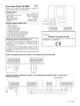
6.2 Electrical connections
The swing-joint in the picture (which is factory made) is for a left-hand barrier (see par. 5.8).
24V (d.c.) Motor
Gearmotor, endstop
Closing
micro-switch
Orange
Orange
Blue
Brown
Opening
micro-switch
Terminals for powering up accessories:
- a 24V a.c. con alimentazione a 230V a.c.
- a 24V d.c. con alimentazione a 24V d.c.
Potenza complessiva consentita: 40W
Power source
Powered by 230V AC, 50/60 Hz

&
$
$
}
}
ZL 37
$ $&
*/5&3#-0$$0
'" '$ ' 15
- - -5
-5
./
48$'52
&20$1'2
6(16
)86,%,/(
/,1($$
)86,%,/(
$&&(6625,$
5$//(17$0(172
&$5,&$%$77
(
%$
&
"
9(/2&,7$
%
#
#
Pag.
12
12 - Manual code:
119G25
119G 25 ver.
7.2
7.2 11/2011 © CAME cancelli automatici s.p.a. - The data and information reported in this installation manual are susceptible to change at any time and without obligation on CAME cancelli automatici s.p.a. to notify users.
ENGLISH
Pulsante Stop button (N.C. socket) - Bar stop button.
Excludes automatic closing. For motion to resume, press the command
button or the remote control button.
If unused, set Dipswitch 9 to ON.
Radio and/or button connection (N.O. contact).
- Boom opening and closing command. Pressing the
button inverts movement of the boom.
Check position of Jumper (n.12, page 10) as shown in the
fi gure.
Opening button (N.O. contact) - Bar opening command.
Command devices
Button operation: close only – Boom closing
command. This command is obligatory when in
“maintained action”.
Position the jumper as shown in the fi gure.
Open barrier pilot light (contact rating: 24V – 3W max.)
- Signals that the boom is raised, and turns o when the boom is down.
24V DC – 25W output socie
When moving (e.g. the - fl ashing light). DIP 3 on OFF
- Flashing during the opening and closing cycles.
Operates during the opening and closing cycles and when the
barrier is closed. DIP 3 on ON
Signalling devices

%
#
#
RX
%
#
#
RX
%
#
#
./ # .#
RX
%
#
#
./ # .#
RX
TX
TX
TX
TX
#
#
Pag.
13
13 - Manual code:
119G25
119G 25 ver.
7.2
7.2 11/2011 © CAME cancelli automatici s.p.a. - The data and information reported in this installation manual are susceptible to change at any time and without obligation on CAME cancelli automatici s.p.a. to notify users.
ENGLISH
(N.C. )Contact for “immediate closing”
Automatic bar closing after an obstacle comes within
the range of the safety devices.
If unused, set Dipswitch 8 to ON.
DIR photocells
DIR photocells
Safety devices
DOC photocells
DOC photocells
Contact (N.C.) for “immediate closing”
If not used, position Dip switch 8 to ON.
Contact (N.C.) for “re opening when closing”
If not used, short-circuit contact 2-C1.
if unused
if unused
Contact (N.C.) for “re-opening while closing”
- input for safety devices like photocell, compliant with
EN 12978. When the boom is in closing cycle, the contact
opening causes the movement to invert until boom is fully
opened.
If not used, short-circuit contact 2-C1.

ZL 37
$ $&
*/5&3#-0$$0
'" '$ ' 15
- -
-5
-5
./
48$'52
&20$1'2
$)
352*
7&$
6(16
)86,%,/(
/,1($$
)86,%,/(
$&&(6625,$
5$//(17$0(172
&$5,&$%$77(5,(
%$
&
"#
9(/2&,7$
0/
ZL 37
$ $&
*/5&3#-0$$0
'" '$ ' 15
- -
-5
-5
./
48$'52
&20$1'2
$)
352*
7&$
6(16
)86,%,/(
/,1($$
)86,%,/(
$&&(6625,$
5$//(17$0(172
&$5,&$%$77(5,(
%$
&
"#
9(/2&,7$
0/
352*
7&$
6(16
)86,%,/(
$&&(6625,$
3
#-0$$0
0/
21
2))
DIP SWITCH
Pag.
14
14 - Manual code:
119G25
119G 25 ver.
7.2
7.2 11/2011 © CAME cancelli automatici s.p.a. - The data and information reported in this installation manual are susceptible to change at any time and without obligation on CAME cancelli automatici s.p.a. to notify users.
ENGLISH
6.4 Settings
6.3 Selecting functions
1 ON Automatic closing enabled;
2 ON Radio command operation “open only” enabled (with
radiofrequency card slot);
2 OFF Radio command operation “open-close-inversion”
enabled (with radiofrequency card slot);
3 ON 24V voltage in output on terminals 10-E during movement
cycles and when in the barrier closed position, enabled;
3 OFF 24V voltage in output on terminals 10-E during barrier
movement cycles, enabled;
4 ON “man present” function enabled;
5 ON Pre-fl ashing for 5 seconds while opening and closing,
enabled;
6 ON Obstacle detection (when motor is at end of stroke),
enabled;
7 ON “Slave” operation (motor is controlled externally) enabled;
8 OFF Immediate closing function enabled; activate safety
device (2-C5);
9 OFF “Stop” button enabled; activate safety device (1-2);
10 ON Function that increases the braking action on the barrier
enabled.
Trimmer T.C.A. = Automatic closing time min. 1”, max. 120”.
Trimmer SENS. = Sensitivity of the amperometric device (min./ max.)
7 Enabling the radio command
Connect RG58 antenna cable to the proper terminals.
Antenna

ZL 37
$ $&
*/5&3#-0$$0
'" '$ ' 15
- -
-5
-5
./
48$'52
&20$1'2
$)
352*
7&$
6(16
)86,%,/(
/,1($$
)86,%,/(
$&&(6625,$
5$//(17$0(172
&$5,&$%$77(5,(
%$
&
"#
9(/2&,7$
0/
TOP TAM
TOUCH
TCH 4024 • TCH 4048
TOP
TOP-432A • TOP-434A
TOP-302A • TOP-304A
CAME
CA
M
E
C
AME
C
AM
E
TOP
TOP-432NA • TOP-434NA
TOP-862NA • TOP-864NA
TOP-432S
TWIN
TWIN 2 • TWIN 4
TAM
T432 • T434 • T438
TAM-432SA
CAME
CAME
CAME
CAME
CAME
CAME
CAME
CAME
CAME
TFM
T132 • T134 • T138
T152 • T154 • T158
Pag.
15
15 - Manual code:
119G25
119G 25 ver.
7.2
7.2 11/2011 © CAME cancelli automatici s.p.a. - The data and information reported in this installation manual are susceptible to change at any time and without obligation on CAME cancelli automatici s.p.a. to notify users.
ENGLISH
Lock the radiofrequency card into the electronic card AFTER CUTTING OFF THE POWER SUPPLY (or after disconnecting the batteries).
N.B.: the electronic card only recognises the radiofrequency card when the power is on.
AF Card
Transmitters
Only for the AF43S / AF43SM radio frequency cards:
- position the jumper as illustrated depending on the series of
transmitters used.
Radio frequency card
Frequency-MHz radiofrequency
card
Series of
transmitters
FM 26.995 AF130 TFM
FM 30.900 AF150 TFM
AM 26.995 AF26 TOP
AM 30.900 AF30 TOP
AM 40.685 AF40 TOUCH
AF43S / AF43SM TAM / TOP
AF43SR ATOMO
AF43S / AF43TW TWIN
AM 868.35 AF868 TOP
See attached instructions

ZL 37
$ $&
*/5&3#-0$$0
'" '$ ' 15
- -
-5
-5
./
48$'52
&20$1'2
$)
352*
7&$
6(16
)86,%,/(
/,1($$
)86,%,/(
$&&(6625,$
5$//(17$0(172
&$5,&$%$77(5,(
%$
&
"#
9(/2&,7$
0/
ZL 37
$ $&
*/5&3#-0$$0
'" '$ ' 15
- -
-5
-5
./
48$'52
&20$1'2
$)
352*
7&$
6(16
)86,%,/(
/,1($$
)86,%,/(
$&&(6625,$
5$//(17$0(172
&$5,&$%$77(5,(
%$
&
"#
9(/2&,7$
0/
ATOMO
AT01 • AT02
AT04
CAME
CAME
CAME
Pag.
16
16 - Manual code:
119G25
119G 25 ver.
7.2
7.2 11/2011 © CAME cancelli automatici s.p.a. - The data and information reported in this installation manual are susceptible to change at any time and without obligation on CAME cancelli automatici s.p.a. to notify users.
ENGLISH
Radio card
PROG
- Keep pressed the PROG button on
the electronic board. The LED light
will fl ash
- Press the button of the transmitter to be
memorie. The LED light will stay lit to signal
that memorisation was successful.
Intermittent LED
LED light ON
Memorising
N.B.: to change code at a later date, just
repeat the described sequence.
8 Adjusting closing-opening and deceleration speed
To adjust the motion speed move the “A” faston connector. For slowdowns move the “B” faston connector.
Eg: max. speed during opening and closing - max. deceleration (see drawing below).
Deceleration
Speed
See instructions attached to
AF43SR radiofrequency card

CAME
O
C
M
Max.
Med.
Min.
Min.
Max.
Velocità
Speed
Geschw.
Vitesse
Velocidad
Rallentamento
Deceleration
Geschw.
Ralentissement
D
Ab
e
n
c
a
el
h
e
m
ra
e
ción
2
1
3
4
5
6
7
8910
0
Rall.
Vel.
7
4
ZL 37
CONTROL PANEL
"B"
"A"
line fuse
motor fuse
accessories fuse
5DOOHQWDPHQWR
9HORFLW¢
ZL 37
$ $&
*/5&3#-0$$0
'" '$ ' 15
- -
-5 -5
./
48$'52
&20$1'2
$)
352*
7&$
6(16
)86,%,/(
/,1($$
)86,%,/(
$&&(6625,$
5$//(17$0(172
&$5,&$%$77(5,(
%$&
"#
9(/2&,7$
0/
*/5&3#-0$$0
$ $&
./
'" '$ ' 15
5DOOHQWDPHQWR
9HORFLW¢
ZL 37
$ $&
*/5&3#-0$$0
'" '$ ' 15
- - -5 -5
./
48$'52
&20$1'2
$)
352*
7&$
6(16
)86,%,/(
/,1($$
)86,%,/(
$&&(6625,$
5$//(17$0(172
&$5,&$%$77(5,(
%$&
"#
9(/2&,7$
0/
5DOOHQWDPHQWR
9HORFLW¢
ZL 37
$ $&
*/5&3#-0$$0
'" ' $
'15
- -
-5 -5
./
48$'52
&20$1'2
$)
352*
7&$
6(16
)86,%,/(
/,1($$
)86,%,/(
$&&(6625,$
5$//(17$0(172
&$5,&$%$77(5,(
%$&"#
9(/2&,7$
0/
SX DX
$)
0/
*/5&3#-0$$0
$ $&
./
'" '$ ' 15
*/5&3#-0$$0
$ $&
Pag.
17
17 - Manual code:
119G25
119G 25 ver.
7.2
7.2 11/2011 © CAME cancelli automatici s.p.a. - The data and information reported in this installation manual are susceptible to change at any time and without obligation on CAME cancelli automatici s.p.a. to notify users.
ENGLISH
- Decide which will be the Master barrier (or pilot barrier, that is, which motor will command both barriers) and which will be the Slave (the
motor piloted by the Master).
9 Connecting two combined barriers that have a single command
1) On one of the two control panels, set Dip 7 to ON
in order to select the motor controlled externally (SLAVE).
2) Wire only the normal the electrical connections on
the (MASTER) terminal board.
Control panel
for the 2
nd
motor (SLAVE)
Control panel
for 1
st
motor (MASTER)
Terminals for 2nd motor
(SLAVE)
Terminals for 1st motor
(MASTER)
3) Connect the two control
panels using the INTERLOCK
terminals as shown in the fi gure.
Shielded cable
2402C 22AWG
Red
Black
Red
Black

Pag.
18
18 - Manual code:
119G25
119G 25 ver.
7.2
7.2 11/2011 © CAME cancelli automatici s.p.a. - The data and information reported in this installation manual are susceptible to change at any time and without obligation on CAME cancelli automatici s.p.a. to notify users.
ENGLISH
9 Safety instructions
This product must only be employed for its originally intended use. Any other use is wrong and potentially dangerous. The manu-
facturer cannot be held liable for any damages resulting from wrongful, erroneous or negligent uses.
Avoid using near mechanical moving parts. Stay out of the opening/closing arc when operator is in motion.
Do not exercise force against the motion of the operator as this could result in potentially dangerous situations.
Do not allow children to play or loiter within the opening/closing arc of the operator. Keep remote controls and any other command
device out the reach of children, to prevent operator from being activated by accident.
In the event of anomalous behaviour, stop using the operator immediately.
Danger of crushing hands
Danger! High voltage
No transit during operation
Important safety instructions
10 Maintenance
10.1 Periodic maintenance
Periodic maintenance to be carried out by the end-user is as follows: wipe clean the glass surface of the photocells;
check that the safety devices work properly; remove any obstruction.
We suggest checking the state of lubrication and tightness of the anchoring screws on the operator.
-To check the efficiency of the safety devices, move an object in front of the photocells when gate is closing. If the operator
inverts the motion or stops, the photocells are working properly.
This is the only maintenance procedure to be bar out with the power source connected.
-Before performing any maintenance procedures, cut off the main power, to prevent possible accidents due to bar movement.
-To clean the photocells use a water dampened cloth. Do not use solvents or other chemical products which may ruin the
devices.
-Make sure there are no plants within the photocell’s beam, and that the bar motion is free of any obstacles.
Page is loading ...
Page is loading ...
Page is loading ...
Page is loading ...
-
 1
1
-
 2
2
-
 3
3
-
 4
4
-
 5
5
-
 6
6
-
 7
7
-
 8
8
-
 9
9
-
 10
10
-
 11
11
-
 12
12
-
 13
13
-
 14
14
-
 15
15
-
 16
16
-
 17
17
-
 18
18
-
 19
19
-
 20
20
-
 21
21
-
 22
22
-
 23
23
-
 24
24


CAME G4001 Installation guide
- Type
- Installation guide
Ask a question and I''ll find the answer in the document
Finding information in a document is now easier with AI
Related papers
-
CAME BX-243C, BX-243C110 Installation guide
-
-
-
-
-
CAME FE40230 Installation guide
-
-
-
-
Other documents
-
 SEAV LG 2020 Owner's manual
-
Transmitter LEDFLADUAL Owner's manual
-
Weatherables WBGA-HINGEALUMNL-NW Operating instructions
-
 Key Automation 580TURBO400K User manual
-
Marantec Parc 100 Owner's manual
-
Chamberlain LiftMaster CB24 Installation guide
-
Dahua IPMECD-105X User manual
-
Hikvision DS-TMG4B0 User manual
-
-
Proteco Q90BD User manual

