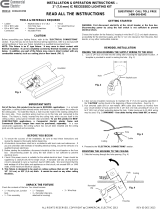
Page is loading ...

www.TaskLighting.com
DesignAndSupport@TaskLighting.com
Customer Service: 800-445-6404
Design Services & Tech Support: 866-848-9094
LIGHTED POWER STRIP
installation instructions
January 2019

Customer Service: 800.445.6404 • Design Services/Technical Support: 866.848.9094 • TaskLighting.com
Lighted Power Strip DV Series
Installation Instructions for LPS WITH Built-In Power Supply
Turn power o at panel. Carefully pry open each
piece with tool (provided). Insert Romex connector into
knockout hole inside of back frame. Pull wires into LPS.
Tool
WTWT
GRN
BKBK
120V
DIVIDER PLATE
SWITCH
DRIVER
RED +
BLUE -
WT
WT
WT GRN
GRN
GRN
BK
BK
BK
General Guidelines
• Power source MUST be a 20 amp branch circuit protected by a GFCI at the panel or GFCI prior to the connection at LPS.
• All wiring must meet NEC® and local codes.
• Light valance recommended.
• Firmly insert plug straight into receptacle, applying equal pressure to both blades at the same time. Gently rock plug, if needed.
WTWT
GRN
BKBK
120V
DIVIDER PLATE
SWITCH
DRIVER
RED +
BLUE -
WT
WT GRN
GRN
BK
BK
Factory
Wired
Factory
Wired
Secure LPS to wall by screwing into wall studs or
use anchors provided. Connect BLACK Romex
wire to BLACK wire from receptacles and switch.
Connect WHITE Romex wire to WHITE wire from
receptacles and driver. Ground all GREEN wires to
PEM studs inside of back frame.
Wiring for Combined Light and Receptacle Circuit - Non Dimmable
To terminate last LPS, use wire nuts on ends
of wires.
When connecting 2 or more LPS xtures, run
Romex from xture to xture. Ground each
section to the next.
Snap cover in place and turn power on.
Secure LPS to wall by screwing into wall studs or
use anchors provided. If running two circuits, one
for receptacles, one for lighting, connect xture
wires to appropriate Romex wires. BLACK to
BLACK. WHITE to WHITE. Ground all GREEN wires
to PEM studs inside of back frame.
Wiring for Separate Light and Receptacle Circuits
Bottom of Cabinet
Step 1 Step 2
Step 3
Step 4
To terminate last LPS, use wire nuts on ends
of wires.
When connecting 2 or more LPS xtures, run
Romex from xture to xture. Ground each
section to the next.
Snap cover in place and turn power on.
Step 2
Step 3
Step 4
Step 1
12-1/2” Fixture Shown
12-1/2” Fixture Shown
120V for
receptacles
120V
for lights

Customer Service: 800.445.6404 • Design Services/Technical Support: 866.848.9094 • TaskLighting.com
120V Receptacle
Circuit. Must be
GFCI Protected.
(non dimmable)
Lighting Circuit
Back Frame
Positive (+)
Negative (-)
Wiring Diagram for Separate Light & Receptacle Circuits
Back Frame
Cover
Positive (+)
Negative (-)
Wiring Diagram for Combined Light & Receptacle Circuit - Non Dimmable
Cover
18-1/2” Fixture Shown
18-1/2” Fixture Shown
Divider Plate
Divider Plate
DRIVER
DRIVER
120V Receptacle
Circuit. Must be
GFCI Protected.
Lighted Power Strip DV Series
Wiring Diagram for 18-1/2" LPS WITH Built-In Power Supply

Customer Service: 800.445.6404 • Design Services/Technical Support: 866.848.9094 • TaskLighting.com
Lighted Power Strip RM Series
Installation Instructions for LPS WITHOUT Built-In Power Supply
Using appropriate knockout hole, pull low voltage
wire from remote power supply into the low voltage
space, connect BLACK wire (negative) to BLACK
wire from lights and RED wire (positive) to RED wire.
Snap cover in place and turn power on.
Turn power o at panel. Carefully pry open
each piece with tool (provided). Insert
Romex connector into knockout hole
inside of back frame. Pull wires into LPS.
General Guidelines
• Power source MUST be a 20 amp branch circuit protected by a GFCI at the panel or GFCI prior to the connection at LPS.
• All wiring must meet NEC® and local codes.
• Light valance recommended.
• Firmly insert plug straight into receptacle, applying equal pressure to both blades at the same time. Gently rock plug, if needed.
Secure LPS to wall by screwing into wall studs or
use anchors provided. Connect BLACK to BLACK,
WHITE to WHITE. Ground all GREEN wires to PEM
studs inside of back frame.
Bottom of Cabinet
Remote Power Supply- 120V Entry
12-1/2” Fixture Shown
GRN
GRN
GRN
GRN
BK
WT
BK
WT
BK
120V
DIVIDER PLATE
LOW VOLTAGE
RED +
BLACK -
WT
When connecting two LPS, run Romex from xture
to xture. Ground each section to the next.
Remote Power Supply-Low Voltage Entry
To terminate last LPS, use wire nuts on ends of wires.
Tool
18-1/2” Fixture Shown
Step 2
Step 3
Step 4
Step 1
Step 5
15vDC wire
120V Circuit
Positive (+)
Negative (-)
Back Frame
Cover
Divider Plate
/
