Page is loading ...

Agilent Technologies
Agilent 16800 Series
Portable Logic Analyzers
Service Guide

Notices
© Agilent Technologies, Inc. 2006, 2007,
2011-2013
No part of this manual may be reproduced
in any form or by any means (including
electronic storage and retrieval or transla-
tion into a foreign language) without prior
agreement and written consent from Agi-
lent Technologies, Inc. as governed by
United States and international copyright
laws.
Manual Part Number
16800-97014
Edition
Sixth edition, June 2013
Printed in Malaysia
Agilent Technologies, Inc.
1900 Garden of the Gods Road
Colorado Springs, CO 80907 USA
Warranty
The material contained in this docu-
ment is provided “as is,” and is sub-
ject to being changed, without notice,
in future editions. Further, to the max-
imum extent permitted by applicable
law, Agilent disclaims all warranties,
either express or implied, with regard
to this manual and any information
contained herein, including but not
limited to the implied warranties of
merchantability and fitness for a par-
ticular purpose. Agilent shall not be
liable for errors or for incidental or
consequential damages in connection
with the furnishing, use, or perfor-
mance of this document or of any
information contained herein. Should
Agilent and the user have a separate
written agreement with warranty
terms covering the material in this
document that conflict with these
terms, the warranty terms in the sep-
arate agreement shall control.
Technology Licenses
The hardware and/or software described in
this document are furnished under a
license and may be used or copied only in
accordance with the terms of such license.
Restricted Rights Legend
If software is for use in the performance of
a U.S. Government prime contract or sub-
contract, Software is delivered and
licensed as “Commercial computer soft-
ware” as defined in DFAR 252.227-7014
(June 1995), or as a “commercial item” as
defined in FAR 2.101(a) or as “Restricted
computer software” as defined in FAR
52.227-19 (June 1987) or any equivalent
agency regulation or contract clause. Use,
duplication or disclosure of Software is
subject to Agilent Technologies’ standard
commercial license terms, and non-DOD
Departments and Agencies of the U.S. Gov-
ernment will receive no greater than
Restricted Rights as defined in FAR
52.227-19(c)(1-2) (June 1987). U.S. Govern-
ment users will receive no greater than
Limited Rights as defined in FAR 52.227-14
(June 1987) or DFAR 252.227-7015 (b)(2)
(November 1995), as applicable in any
technical data.
Safety Notices
CAUTION
A CAUTION notice denotes a haz-
ard. It calls attention to an operat-
ing procedure, practice, or the like
that, if not correctly performed or
adhered to, could result in damage
to the product or loss of important
data. Do not proceed beyond a
CAUTION notice until the indicated
conditions are fully understood and
met.
WARNING
A WARNING notice denotes a
hazard. It calls attention to an
operating procedure, practice, or
the like that, if not correctly per-
formed or adhered to, could result
in personal injury or death. Do not
proceed beyond a WARNING
notice until the indicated condi-
tions are fully understood and met.
2 16800 Series Portable Logic Analyzers Service Guide

16800 Series Portable Logic Analyzers Service Guide 3
The Agilent 16800 Series Logic Analyzers—At a Glance
The Agilent Technologies 16800 Series logic analyzers are
standalone benchtop logic analyzers that range from 34 to
204 logic acquisition channels and 48 pattern generator
channels, depending on the model.
Model Comparison
Features, Logic Acquisition
•1 M to 32 M memory depth per channel (depending on
memory option), software upgradeable.
•250 MHz or 500 Mb/s maximum state data rate
(depending on state speed option), software upgradeable.
The 500 Mb/s maximum state data rate option is available
on the 68- channel and above logic analyzer models.
•1 GHz, 64 M deep timing analysis on half channels.
•Eye finder (automatic threshold and sample position
setup) feature.
•4 GHz timing zoom with 64 K memory depth.
Tabl e 1 Model comparisons
Agilent model number 16801A 16802A 16803A 16804A 16806A 16821A 16822A 16823A
Logic acquisition channels 34 68 102 136 204 34 68 102
Pattern generator channels 00000484848

4 16800 Series Portable Logic Analyzers Service Guide
Features, Mainframe
•Built- in 15 inch TFT color LCD display, 1,024 x 768
(XGA) resolution. Touch screen with 16800A Option 103.
•250 GB hard disk drive (or external hard drive 16800A
Option 109).
•10/100 Base- T LAN port.
•USB 2.0 ports (six total, two on front, four on back).
•One PCI expansion slot.
•One PCI Express x1 expansion slot.
•Windows® XP Professional operating system. The 16800
Logic Analyzers with serial number MY50370000 or
greater are shipped with Windows 7 operating system.
•Agilent Logic Analyzer application which takes the
complexity out of making logic analyzer measurements.
You can perform all operations directly from one window.
Features, Pattern Generator
•24 channels at 300 MHz clock; 48 channels at 180 MHz
clock.
•Memory Depth: 16,777,216 vectors in half- channel mode.
•Logic Level (data pods): TTL, 3- state TTL/3.3v, 3- state
TTL/CMOS, ECL/PECL/LVPECL terminated, ECL
unterminated, and differential ECL (without pod).
•Data Inputs: 3- bit pattern level sensing (clock pod).
•Clock Output: Synchronized to output data, delay of 7 ns
in 14 steps (clock pod).
•Clock Input: DC to 300 MHz (clock pod).
•Internal Clock Period: Programmable from 1 MHz to
300 MHz in 1 MHz steps.
•External Clock Period: DC to 300 MHz.
•External Clock Duty Cycle: 1.3 ns minimum high time.
Supplied Accessories
•PS2 mouse.
•PS2 keyboard.
•Accessory pouch and power cord.
Optional Accessories:
•Probes.

16800 Series Portable Logic Analyzers Service Guide 5
Service Strategy
The service strategy for this instrument is the replacement
of defective assemblies. This service guide contains
information for finding a defective assembly by testing and
servicing the 16800 Series logic analyzer.
This instrument can be returned to Agilent Technologies for
all service work, including troubleshooting. Contact your
nearest Agilent Technologies Sales Office for more details.
Contacting Agilent Technologies
To locate a sales or service office near you, go to
www.agilent.com/find/contactus.

6 16800 Series Portable Logic Analyzers Service Guide
In this Service Guide
This book is the service guide for the 16800 Series logic
analyzers and is divided into eight chapters.
Chapter 1, “General Information” contains information about
the instrument including accessories, specifications and
characteristics, and a list of the equipment required for
servicing the instrument.
Chapter 2, “Preparing for Use” tells how to prepare the
instrument for use.
Chapter 3, “Testing Performance” gives instructions on how
to test the performance of the instrument.
Chapter 4, “Calibrating and Adjusting” contains calibration
instructions for the instrument.
Chapter 5, “Troubleshooting” contains self- tests and
flowcharts for troubleshooting the instrument.
Chapter 6, “Replacing Assemblies” tells how to replace the
instrument and assemblies of the instrument, and how to
return them to Agilent Technologies.
Chapter 7, “Replaceable Parts” lists replaceable parts, shows
exploded views, and gives ordering information.
Chapter 8, “Theory of Operation” explains how the
instrument works and what the self- tests are checking.
Revision History
Table 2 Revision History
Revision Reason
16800-97014, November
2011
(this version)
Changes in replaceable part numbers and the
recovery procedure for the 16800 logic analyzers
that are shipped with Windows 7 installation
(serial numbers MY50370000 or greater)
16800-97004, June 2007 Module interface board (MIB), chassis, and cover
changes. These part changes appear in serial
numbers above: MY46000901/SG46000901
16800-97003, August 2006 Changes to Testing Performance procedure.
16800-97002, July 2006 Changes to Testing Performance procedure.
16800-97001, July 2006 First edition.

16800 Series Portable Logic Analyzers Service Guide 7
Contents
1 General Information
Accessories 14
Available 14
Specifications 15
Characteristics 16
Electrical 16
Operating Environment (for indoor use only) 17
Non-Operating Environment 17
Dimensions 18
Weight 18
Recommended Test Equipment 19
2 Preparing for Use
To inspect the logic analyzer 22
To apply power 22
To clean the instrument 23
To start the user interface 23
To test the logic analyzer 23
3 Testing Performance
To perform the power-up tests 26
Logic Analyzer Test Strategy 27
Te st I nt e rv al 27
Test Record Description 27
Te st E qu ip me nt 27
Instrument Warm-Up 27
To Assemble the SMA/Flying Lead Test Connectors 28
To Test the Minimum Master to Master Clock Time and Minimum Eye
Width 33
Equipment Required 34

8 16800 Series Portable Logic Analyzers Service Guide
Contents
Prepare the Logic Analyzer for Testing 35
Perform System Self-Tests 36
Set Up the Test Equipment 37
Connect the Test Equipment 39
Connect the Logic Analyzer Pod to the 8133A Pulse Generator 39
Connect the 8133A Pulse Generator Output to the 54845A
Oscilloscope 40
Verify and adjust 8133A pulse generator DC offset 41
Deskew the oscilloscope 42
Set the 8133A pulse width 43
Configure the Logic Analyzer 45
Adjust the sample positions using eye finder 48
Test Pod 1 in 250 Mb/s Mode 52
Determine PASS/FAIL (1 of 2 tests) 52
Close the eye finder and Analyzer Setup dialogs 52
Configure the markers 52
Determine PASS/FAIL (2 of 2 tests) 54
Test the complement of the bits (250 Mb/s mode) 55
Test Pod 2 in 250 Mb/s Mode 57
Test the complement of the bits (Pod 2, 250 Mb/s mode) 58
Test Pods 3 and 4 in 250 Mb/s Mode 58
Test the Remaining Pods in 250 Mb/s Mode 59
Set up the second E5383A Flying Lead Probe Set 59
Test the remaining pods 59
Test Pod 1 in 500 Mb/s Mode 60
Determine and set eye finder Position (500 Mb/s mode) 61
Test the complement of the bits (Pod 1, 500 Mb/s mode) 63
Test Pod 2 in 500 Mb/s Mode 64
Set up the second E5383A Flying Lead Probe Set 64
Test Pod 2 in 500 Mb/s mode 64
Test the complement of the bits (Pod 2, 500 Mb/s mode) 65
Test the Remaining Pods in 500 Mb/s Mode 65
To re-assign pods reserved for time tag storage 66
Conclude the State Mode Tests 66
Performance Test Record 68
4 Calibrating and Adjusting
Calibration Strategy 70

16800 Series Portable Logic Analyzers Service Guide 9
Contents
5 Troubleshooting
To use the system troubleshooting flowcharts 72
To use the logic acquisition troubleshooting flowcharts 78
To use the pattern generator troubleshooting flowcharts 81
To troubeshoot system power problems 84
Power Supplies 84
To check the power supply voltages 84
To run the self-tests 88
Logic Acquisition Self-Test Descriptions 89
Pattern Generator Self-Tests Description 92
To exit the test system 96
To restore the system software 97
On a Legacy 16800 Series Logic Analyzer with Windows XP
Installation 97
On a 16800 Series Logic Analyzer with Windows 7 Installation 97
Contacting Agilent Service/Support 101
To test the logic acquisition cables 102
To assemble the 2 x 9 test connectors 102
Set up the test equipment 105
Connect the test equipment 105
Configure the logic analyzer to test Pod 1 106
Adjust sampling positions using eye finder 109
Connect and configure the logic analyzer to test other pods 111
To verify pattern generator output 114
6 Replacing Assemblies
16800 Series Logic Analyzer Disassembly/Assembly 118
Replacement Strategy 118
Tools R eq ui r e d 118
To save the license file 119
To prepare the instrument for disassembly 120
To power off the system 120
To remove and replace the cover 122
To remove and replace the power supplies 123
600 watt power supply 123
Secondary power supply 124
To remove and replace the PCI or display board 126
To remove and replace the motherboard 127

10 16800 Series Portable Logic Analyzers Service Guide
Contents
To remove and replace the front panel assembly 129
To remove and replace the backlight inverter board 130
To remove and replace the touch screen controller board 131
To remove and replace the front panel bracket assembly 132
To remove and replace the USB cables 133
To remove and replace the display assembly 134
To remove and replace the keypad and keypad board 136
To remove and replace a measurement card 138
To remove and replace measurement cables 139
To remove and replace a measurement circuit board 141
To remove and replace a pattern generator card 142
To remove and replace the pattern generator probe cable 143
To remove and replace the pattern generator circuit board 144
To replace the hard disk drive 145
If you have a 16800 series Logic Analyzer with Windows XP
installation 145
If you have a 16800 series Logic Analyzer with Windows 7
installation 145
To remove and replace the tray assembly 146
To remove and replace the fans 147
60 mm fan 147
92 mm fans 148
To remove and replace the line filter assembly 149
To replace the module interface board 150
Returning Assemblies 151
7 Replaceable Parts
Ordering Replaceable Parts 154
Exchange Assemblies 154
Power Cables and Plug Configurations 155
System Replaceable Parts List 157
Cover and Front Panel Assemblies 158
Frame 160
Measurement Card Replaceable Parts List 165
Pattern Generator Card Replaceable Parts 167

16800 Series Portable Logic Analyzers Service Guide 11
Contents
8 Theory of Operation
System Block Level Theory 170
CPU Subsystem 172
PCI board 173
MIB (Module Interface Board) 173
Front Panel Assembly 176
Power Up Routine 177
Logic Acquisition Block-Level Theory 184
Probes 185
Comparators 185
Acquisition IC 185
Memory Controller and Acquisition Memory 186
Master/Expander Connectors 186
Mainframe Interface and Control FPGA 186
Pattern Generation Block-Level Theory 187
Instruction Memory 187
Data Memory 187
Output Driver 188
Clock Circuit 188
CPU Interface 188
Pod 189
Index

12 16800 Series Portable Logic Analyzers Service Guide
Contents

13
Agilent 16800 Series Portable Logic Analyzers
Service Guide
Agilent Technologies
1
General Information
Accessories 14
Specifications 15
Characteristics 16
Recommended Test Equipment 19
This chapter contains information on accessories,
specifications, characteristics, and recommended test
equipment.
See the 16800 Series logic analyzer’s online help for a full
listing of all specifications and characteristics.

14 16800 Series Portable Logic Analyzers Service Guide
1General Information
Accessories
Available
One or more of the following accessories, sold separately, are
required to operate the 16800 Series logic analyzers.
Table 3 Logic Analyzer Accessories Available
Accessories Agilent Part Number
Flying Lead Probe Set E5383A
17-Channel Single-Ended Soft Touch Probe E5396A
34-Channel Single-Ended Soft Touch Probe E5394A
34-Channel Single-Ended Pro-series Soft Touch Probe E5404A
34-Channel Single-Ended Probe (Samtec) E5385A
34-Channel Single-Ended Probe (MICTOR) E5346A
Single-Ended Low Voltage Probe (MICTOR) E5339A
Single-Ended Probe, No Isolation Networks (MICTOR) E5351A

General Information 1
16800 Series Portable Logic Analyzers Service Guide 15
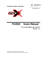
Specifications
The specifications are the performance standards against
which the product is tested.
tWidth
(Data Eye)
vHeight
Individual
Data Channel
vThreshold
0V
Sampling
Position
(Eye Finder
Blue Bar)
Specifications
Parameter 250 Mb/s
mode
500 Mb/s
mode
Notes
Minimum master to
master clock time
4 ns 2 ns 500 Mb/s mode is available only when Option
500 is installed.
tWidth (minimum) 1.5 ns 1.5 ns Specified at probe tip. Eye width as measured
by eye finder may be less.
Specifications verified under the following test conditions:
Parameter 250 Mb/s
mode
500 Mb/s
mode
Notes
Vh 1.3 V 600 mVp-p
Vl 0.7 V
vThreshold 1 V
rise/fall times 150-180 ps
Probe Agilent E5383A Flying Lead Probe

16 16800 Series Portable Logic Analyzers Service Guide
1General Information
Characteristics
The following characteristics are not specifications, but are
typical characteristics for the 16800 Series logic analyzers.
Electrical
Power Requirements
16801A, 16802A, and 16803A: 115/230 Vac +/- 20%, 48- 66Hz,
615 W Max.
16804A, 16806A, 16821A, 16822A, and 16823A: 115/230 Vac
+/- 20%, 48- 66Hz, 775 W Max.
The line voltage is autodetected by the instrument.
CAT II (Line voltage in appliance and to wall outlet).
Pollution degree 2.
Trig ger In
The Trigger In connector is 5V Max pk and DC, CAT I (line
isolated).
Clock In
The Clock In connector is 5.5V Max pk and DC, CAT I (line
isolated).
Probes
Maximum Input Voltage: ± 40 V, CAT I, CAT I = Category I,
secondary power line isolated circuits.
!
!

General Information 1
16800 Series Portable Logic Analyzers Service Guide 17
Operating Environment (for indoor use only)
Non-Operating Environment
Store or ship the instrument in environments within the
following limits:
Table 4 Operating Environment Characteristics
Tempe ra t ur e All models: 0° to + 50° C (+32° to +122° F).
Probes/cables: 0° to + 65° C (+32° to +149° F).
Humidity Relative humidity 8% to 80% at 40° C (104° F). Avoid sudden,
extreme temperature changes which could cause
condensation on the circuit board.
Altitude 0 to 3,000 m (10,000 ft)
Vibration Operating: random vibration 0-500 Hz, 10 minutes per axis,
0.3 g (rms).
Table 5 Non-Operating Environment Characteristics
Tempe ra t ur e Temperature -40°C to +75°C (-40°F to 167°F).
Protect the system from temperature extremes which cause
condensation on the instrument.
Humidity Humidity up to 90% at 65° C (149°F).
Altitude Altitude up to 3,000 meters (10,000 feet)).
Vibration Non-operating: random vibration 0-500 Hz, 10 minutes per axis,
2.41g (rms); and swept sine resonant search, 0-500 Hz, 0.75g,
5-minute resonant dwell at 4 resonances per axis.

18 16800 Series Portable Logic Analyzers Service Guide
1General Information
Dimensions
The following figure provides dimensions for the 16800
Series logic analyzer mainframes in centimeters and inches.
Weight
Table 6 16800 Series Logic Analyzer Weight
Model Max Net Max Shipping
16801A 12.9 kg (28.5 lbs) 19.7 kg (43.5 lbs)
16802A 13.2 kg (28.9 lbs) 19.9 kg (43.9 lbs)
16803A 13.7 kg (30.3 lbs) 20.5 kg (45.3 lbs)
16804A 14.2 kg (31.3 lbs) 21.0 kg (46.3 lbs)
16806A 14.6 kg (32.1 lbs) 21.4 kg (47.1 lbs)
16821A 14.2 kg (31.2 lbs) 20.9 kg (46.2 lbs)
16822A 14.2 kg (31.6 lbs) 21.1 kg (46.6 lbs)
16823A 14.5 kg (32.0 lbs) 21.3 kg (47.0 lbs)

General Information 1
16800 Series Portable Logic Analyzers Service Guide 19
Recommended Test Equipment
Tabl e 7 Recommended Test Equipment
Equipment Critical Specifications Recommended Agilent
Model/Part
Use†
Single-ended Flying Lead Probe Set
(Qty 2)
no substitute E5383A P, T
Ground Leads (Qty 5) no substitute pkg of 5
(Included with E5383A
Probe Set)
T
Pulse Generator 260 MHz,1 ns pulse width, two channels,
≤ 150 ps rise time
8133A Option 003 P, T
150 ps Transition Time Converter
(Qty 4)
Required if pulse generator’s rise time is less
than 150 ps (Voffset=1V, ΔV=600 mV).
Required for 8133A opt. 003
Agilent or HP 15435A P
Oscilloscope ≥ 1.5 GHz bandwidth,
≥ 8 GSa/s sampling rate
54845A or 54845B P
SMA/Flying Lead Test connectors no substitute See “To Assemble the
SMA/Flying Lead Test
Connectors" on page 28
P
2 x 9 Test connectors no substitute See “To assemble the 2 x 9
test connectors" on
page 102
P
SMA Coax Cable (Qty 2) ≥ 18 GHz bandwidth 8120-4948 P
†P = Performance Tests, T = Troubleshooting

20 16800 Series Portable Logic Analyzers Service Guide
1General Information
/