Autodesk 46200-000000-9460 Datasheet

Category
Warranty & support extensions
Type
Datasheet
Autodesk
®
Inventor
TM
Professional
2
Autodesk
®
Inventor
software provides a comprehensive set
of design tools for producing, validating, and documenting
complete digital prototypes—helping manufacturers get
to market faster with fewer physical prototypes and more
innovative products.
Experience your design before its built.
The Autodesk Inventor product family is
redefining traditional CAD workflows by helping
engineers focus on the functional requirements
of a design to drive the creation of complex D
geometry. Reducing the time spent on geometry
allows engineers to spend more time innovating
designs. By rapidly building digital prototypes that
validate a design’s function, engineers can catch
errors before they reach production. With creative
approaches to accelerate and simplify the concept-
to-manufacturing process, Inventor has outsold all
competitors for the seventh consecutive year.
The Right Tools for Your Design Process
Inventor helps designers to realize the benefits of
Digital Prototyping by giving them the freedom to
reuse their existing DWG™ designs in a D design
environment. Inventor lets users read and write
native DWG files without risking inaccurate trans-
lations, and leverage valuable DWG data to build
accurate D part models the first time. Inventor
includes tools to easily create and document D
designs, and provides unparalleled interoperability
with competitive manufacturing applications—
simplifying collaboration with other companies.
Contents
Dynamic Simulation .................................. 4
Stress Analysis ............................................ 6
Tube and Pipe Design ................................ 8
Cable and Harness Design ..................... 10
AutoCAD Integration .............................. 12
Part Design ................................................ 14
Sheet Metal Part Design ......................... 16
Assembly Design ...................................... 18
Design and Manufacturing
Documentation ......................................... 21
Data Management
and Communication ................................ 23
Customization and Automation ........... 26
Learning Resources .................................. 27
Learn More ................................................ 28
3
Specialized Tools for Your Design Needs
The Autodesk Inventor product line provides a
comprehensive and integrated set of design tools
for producing and documenting complete digital
prototypes that validate the form, fit, and function
of a design. The Inventor model is an accurate
D
digital prototype that enables users to check
design and engineering data as they work, mini-
mize the need for physical prototypes, and reduce
costly engineering changes discovered after the
design has been sent to manufacturing.
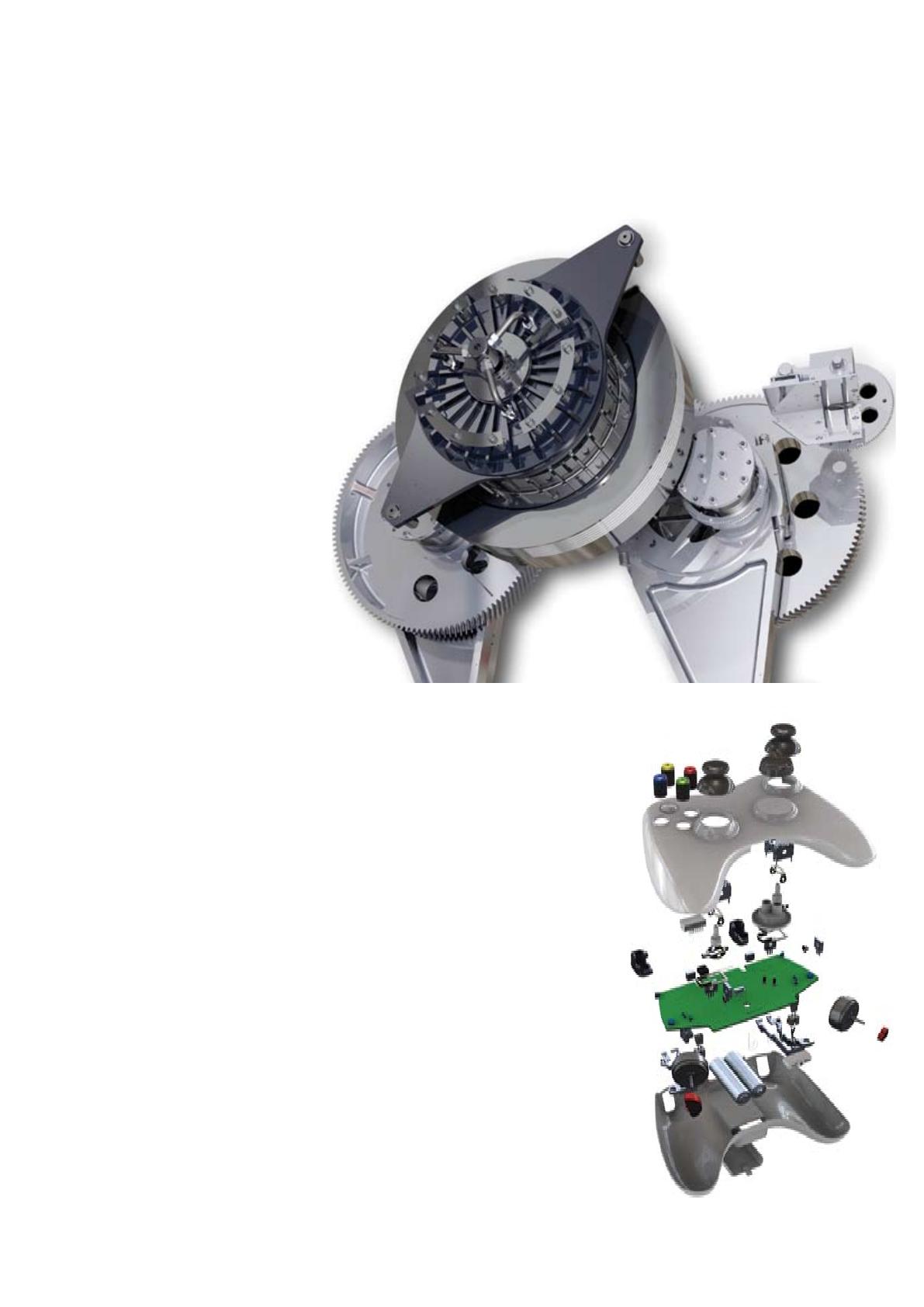
Autodesk Inventor software products combine an
intuitive D design environment for creating parts
and assemblies with functional design tools that
enable engineers to focus on a design’s function
to drive the automatic creation of intelligent com-
ponents such as steel frames, rotating machinery,
tube and pipe runs, and electrical cable and wire
harnesses.
Validating the operating characteristics of
designs before they are built usually requires hir
-
ing expensive consultants. The Inventor product
line includes easy-to-use and tightly integrated
motion simulation and stress analysis functional-
ity, making it possible for any engineer to optimize
and validate the digital prototype to predict how
the design will work under real-world conditions,
before the product or part is ever built.
Generating manufacturing documentation from a
validated D digital prototype helps reduce errors
and associated ECOs (engineering change orders)
before manufacturing. Inventor oers rapid and
accurate output of production-ready drawings
directly from the D model. Inventor product
bundles also include AutoCAD
®
Mechanical soft-
ware for situations that require a high-productivity
D
mechanical drafting tool.
Inventor is tightly integrated with Autodesk data
management applications, enabling the ecient
and secure exchange of design data and promoting
earlier collaboration between design and manufac-
turing workgroups. Dierent workgroups can man-
age and track all components of a digital prototype
with the free* Autodesk
®
Design Review soft-
ware—the all-digital way to review, measure, mark
up, and track changes to designs—allowing for
better reuse of crucial design data, management
of bills of materials (BOMs), and collaboration with
other teams and partners.
With dierent product configurations that oer
specific levels of functionality, no company is
more focused than Autodesk on helping designers
create accurate digital prototypes and bring better
products to market faster at less cost.
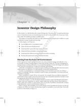
Dynamic Simulation
4
Simulation
Simulate the operation of mechanisms and
motorized assemblies to make sure designs will
work, while reducing physical prototyping costs.
Compute the dynamic operating conditions of
the design throughout its full operating cycle, and
accurately size motors and actuators to sustain
actual operating loads. Analyze positions, veloci-
ties, accelerations, and loads encountered by a
selected component in the mechanism.
With Inventor Professional, designers can use Dynamic
Simulation to predict how a product will work under
real-world conditions, without having to build costly,
time-consuming physical prototypes or waiting for
results from expensive consultants.
Dynamic Simulation
Simply add the
driving loads, friction
characteristics, and
dynamic components.
Then, run the simulation
to validate the design.
Smooth integration with
stress analysis validates
component design with
actual load information,
rather than estimates.
Output to Finite Element Analysis
Transfer reaction forces from discrete time steps
to Autodesk Inventor Stress Analysis or ANSYS
®
Workbench to predict stress and deflection with
accurate peak loads. Size components, such as pins
and linkages, to minimize weight and material costs.
5
Constraint Translation
Quickly and easily set up dynamic simulations to
represent the operating conditions of the design.
The constraint reduction engine analyzes assembly
constraints to identify the relevant rigid bodies
and generate the correct motion joints for simula-
tion. Users can also apply standard geometric
constraints using the included library of motion
joints. Then add springs and dampers to define the
coecient of friction that applies to each joint.
Load Definition
Apply dierent driving loads and torques as well as
time-based force functions using the load profile
editor. Use this tool to investigate the design’s per-
formance under a range of dierent load conditions.
Visualization
Fully interpret the behavior and performance of
your design. Animated D visualization shows dy-
namic motion based on underlying physics models
and the applied load conditions.
Point Trace
Determine accurate component position to help
provide sucient clearance between mechanisms
and fixed structures. Select any point in the model
and use the Trace option to display the selected
point’s location at each step in the simulation. Save
simulation output, including path trace and assem-
bly position, for use in part and assembly design.
Graphing
Use the comprehensive graphing capability to
quickly investigate how the dynamic characteristics
of the design vary through the machine’s operating
cycle. Plot physical parameters—such as position,
force, and acceleration—versus time. Compare
dierent properties at each point in the simulation
cycle using multiple plots on the same graph.
Microsoft Excel Output
Export XY plot data to Microsoft
®
Excel
®
work-
sheets to analyze simulations and incorporate
results in presentations and reports.
Dynamic Simulation
6
The stress analysis functionality in Inventor Professional
helps users understand how parts perform under load,
so they know their designs have sucient strength to
perform without failure.
Stress Analysis
Easy-to-Use, Integrated Analysis
Make design decisions based on analysis results,
not intuition. Integrated finite element analysis
removes the need for translation of the CAD
model, making it easier to use than stand-alone
analysis packages. Users can examine deformation
as well as maximum and minimum stresses to
design higher-quality parts and make sure their
designs meet required safety factors.
Integrated with Dynamic Simulation
Analyze the stress in a moving part at dierent
points in the mechanism’s operating cycle. Import
loads from multiple steps in a dynamic simulation,
and then calculate and view the resulting stresses
in a single analysis run.
The stress analysis tools
are fully integrated with
the dynamic simulation
tools, enabling users to
perform stress analysis
with accurate load condi-
tions that are calculated
directly from the dynam-
ic behavior of the design.
7
Model Simplification
Reduce the time required to generate results from
stress analysis by simplifying part geometry to
suppress features during finite element analysis.
Thin Element Solver
Identify areas of high stress in thin metal parts,
including those made of sheet metal, to help
ensure that they can support the operating loads.
Export Analysis Data to ANSYS
Perform advanced studies without unnecessary
and costly data translation. Inventor analysis
definitions can be exported to ANSYS for use with
additional validation tools.
Share Validation Results
Quickly and easily add analysis results to reports
by exporting to an AVI or graphics file.
Stress Analysis
8
Inventor Professional enables users to reduce the time
required to design tubing, piping, and flexible hose.
Tube and Pipe Design
New Functionality
Simplify the design of pipe runs—or spools—to
fit in complex assemblies or tight spaces.
Automatically routed segments respect predefined
routing styles to present users with alternative
pipe routes that comply with routing rules such
as minimum or maximum length criteria and bend
radius. Alternatively, pipe runs can be defined
manually by creating D sketch geometry or
built up interactively using the route edit tools.
Automatically routed segments can be combined
with user-defined segments for maximum control.
Fittings Library
Improve quality, easily organize parts, and elimi-
nate tedious searching with automatic placement
of the correct part from an extensive library of pip-
ing components. The library includes commonly
used, industry-standard (ANSI, DIN, ISO, and JIS)
fittings, tubing, piping, and hose. Add or modify
properties, including part numbers to existing
parts, and control file names used to instance fit-
tings, pipes, tubes, and other content.
Flexible Hose
Make sure flexible hose and fittings fit properly
using a D digital prototype that drives accurate
manufacturing documentation. The system inserts
appropriate hose fittings from the Content Center
and checks for minimum bend radius based on
the selected hose style. Hose lengths are updated
automatically for use in length roll-up commands.
The rules-based routing
tools in Inventor
Professional select the
appropriate ttings and
help enable pipe runs
to comply with design
rules for minimum and
maximum length, round-
oincrements, and bend
radius.
9
Rigid Tube Routing
Quickly create rigid tubes with superior control
over the shape, bend angles, and radii. Create
rigid tubes with an arbitrary number of bends and
variable custom bend angles and radii. The radius
and rotation handles oer greater control over the
shape of rigid tubes.
Tube and Pipe Styles
Increase the quality and manufacturability of de-
signs by helping to ensure that tube and pipe runs
automatically adhere to preset design standards.
Create tube and pipe styles to support the use of
threaded, welded, and flanged connections. Styles
define the fittings to be used for both automatic
and manual routing, and enforce design rules,
including minimum segment lengths and minimum
bend radii, as well as the maximum length be-
tween couplings.
Hygienic Pipe Runs
Design process lines that comply with sterility and
hygiene standards required for process equip-
ment in the pharmaceutical, food, and personal
care industries. Incorporate the correct slope into
the pipe route, including use of drainable angle
fittings that comply with the American Society
of Mechanical Engineers (ASME) bioprocessing
equipment where needed.
Creating Runs
Automatically populate piping routes with real
parts that adhere to manufacturing standards. The
Populate Route tool turns tube, pipe, and hose
routes into physical pipe runs, automatically plac-
ing fittings, pipe segments, rigid tubes, and hoses
as needed. Standard Inventor parts are created
during this process to make it easy to perform
mass property calculations and interference
checks. In addition, couplings are automatically
placed when pipes reach their maximum length,
and users can specify length cuto increments.
Tube and Pipe Documentation
Create manufacturing deliverables without
redrawing—reducing errors and associated costs.
Fully associative documentation for tube and pipe
runs provides assembly drawings that update
whenever a change is made to the D design.
ISOGEN PCF file output creates isometric piping
drawings in third-party ISOGEN software such
as Alias ISOGEN, and tubing bend tables in ASCII
format provide the information required by tube
bending machines.
Tube and Pipe Design
10
Inventor Professional streamlines cable and harness design
by using wire list information imported from schematic
design packages, including AutoCAD
®
Electrical software.
Cable and Harness Design
Functional Harness Design
Design cable and harness components in D to
reduce manufacturing problems, facilitate output
of manufacturing drawings, and avoid late-stage
engineering change orders. In Inventor, wire list
and connector information is used to drive harness
design with built-in cross-checking of electrical and
mechanical data so users can make sure that all
wires and connectors in the wire list are represented
in the D cable design.
Wire List Import
Maintain electrical design intent and reduce errors
when importing wire lists into the assembly. Quickly
import large wire lists from AutoCAD Electrical or
third-party schematic design applications with de-
tection and correction of missing connectors, pins,
and wire definitions.
Wire Routing
Quickly route thousands of wires while providing
control over the paths of crucial wires. Manual
routing requires explicit selection of the wire’s
path, interactive routing requires selection of the
start/end points and the algorithm chooses the
shortest path, and in automatic routing the system
find the shortest possible path based on all avail-
able paths.
Harness Path Definition
Optimize the design of cable and harness assem-
blies to help ensure proper spacing for manufac-
turing and reduce errors in manufacturing caused
by incomplete product definition. Define harness
and cable paths using a point-and-click methodol-
ogy that creates D virtual conduits (segments) in
the model. Create associative relationships that
help ensure that the harness updates when design
components change. Add points or move existing
points to refine the overall shape of the harness.
Complex electrical
systems are present in
almost every product
or machine, and require
increasingly careful
design of the physical
cables and harnesses.
Incorporating cable and
harness runs—including
ribbon cables—into the
digital prototype saves
users time and money
by calculating accurate
path lengths, avoiding
small radius bends,
and making sure the
electrical components
fit into the mechanical
assembly.
11
Harness Validation
Improve cable quality and manufacturability, and
prevent costly recalls and product failures by ad-
hering to design standards. Inventor automatically
calculates quality parameters, including bundle
diameter, bend radius, and wire lengths, whenever
changes are made to the harness. As a result, users
can eliminate the time-consuming and error-
prone process of manually measuring a hardware
prototype.
Harness Documentation
Quickly and easily create manufacturing docu-
mentation before building the first article. Since
cable and harness geometry is native to Inventor,
users can create assembly documentation showing
accurate details of cable and harness placement.
Comprehensive tools for the rapid generation of
harness documentation include the following:
Automatic nailboard diagrams for D
wire har-
nesses, cables, and ribbon cables that update
automatically as the D design changes
Reports including wire run lists, termination
charts, cut tables, and other reports needed for
the design and manufacture of the harness
XML output files for transferring the final wire
connectivity information to streamline the cre-
ation of schematics and wiring diagrams using
AutoCAD Electrical or other schematic design
software
Ribbon Cables
Reduce errors in the design of electronic equipment
by incorporating ribbon cables in the D digital pro-
totype. Add ribbon cables between connectors with
full control over the locations of twists and folds.
Connector Authoring
Set up company-specific connector libraries to
encourage the use of preferred connectors in the
design of electrical products. Inventor includes an
extensive library of connectors to simplify selec-
tion and placement. The Content Center provides
an easy-to-use editor to add user-defined connec-
tors, as well as add or modify properties such as
part numbers and default file names used when
instancing connectors.
Cable and Harness Design
12
Inventor makes it easy for users of AutoCAD
®
software to
realize the benefits of Digital Prototyping by leveraging
investments in AutoCAD expertise and DWG
design data.
AutoCAD Integration
Template Synchronization
Open a DWG file in Inventor and automatically
create layers and dimension and text styles based
on the AutoCAD styles in the DWG file, thus
reducing the time required to create drawings that
comply with customers’ drawing standards.
Ease of Use
Reduce the time and training required for
AutoCAD users to become proficient in D
design workows. Simplify the transition from
AutoCAD software to Inventor in a familiar design
environment with recognizable icons, AutoCAD-
compatible shortcuts, cursor-based prompts,
and command redo. User profiles enable users to
configure Inventor to match the way they work,
with out-of-the-box profiles for AutoCAD and
Inventor experts. In addition, users can transfer
their settings between dierent computers by
exporting the profile to XML.
Inventor delivers the
industry’s leading
integration of D and
D design, providing
direct read and write
of native DWG files,
while maintaining full
associativity to the
D model—without
the need for data-
compromising
translators.
With Inventor, reuse
valuable data with
rapid access to existing
D information. And,
because users can save
drawings as DWG files,
they can easily share
insights gained from the
digital prototype with
partners and suppliers
who rely on AutoCAD
software. Views
generated from D part
and assembly designs,
such as schematics and
plant layouts, can also be
combined with AutoCAD
data. Users can then
update D drawings by
inserting a view of new
D designs—reducing
the cost of upgrading
existing equipment.
13
DWG Save
Integrate DWG technology into the D design
workow to take advantage of existing skills; easily
combine part, assembly, and schematic drawings
data; and streamline communication with suppliers
and partners who rely on DWG technology. This
feature stores Inventor drawing views in the DWG
file to provide view, plot, and measure capabilities
in AutoCAD with complete visual fidelity, while
preserving fully associative drawing updates.
Direct DWG Open
Gain access to existing D design data without
installing or learning AutoCAD software. Open
AutoCAD drawings directly in the Inventor ap-
plication to view, plot, and measure using familiar
Inventor commands. Incorporate existing D
design data into D design workows using Copy
and Paste commands.
AutoCAD Blocks from Inventor Views
Reduce the cost of using D for upgrade projects
originally designed in D. This feature generates
AutoCAD blocks from Inventor drawing views so
users can redesign subassemblies using Inventor
and then integrate the new drawing views directly
into the original drawings.
Inventor and AutoCAD Mechanical
Interoperability
Accelerate time to market and reduce errors by
enabling associative D and D collaboration.
With this interoperability, AutoCAD Mechanical
software creates drawings of Inventor components
by enabling users to open native Inventor parts
and assemblies. When the design changes in
Inventor, the AutoCAD Mechanical drawing is
automatically updated.
AutoCAD Integration
14
Inventor software helps designers reach the next level of
eciency by making it easier to reuse design data, convey
design intent, and work with fully associative models to
make sure any changes to the part design are reflected in
the assembly model and drawing files.
Part Design
Sketching
Evaluate dierent design ideas before creating
detailed part and assembly models. By using the
Inventor sketch environment, designers can quickly
capture design ideas as versatile D layouts. By
combining the power of constraints with easy-to-
use tools for modifying sketches, designers can try
dierent design concepts and control color and line
style to help convey design ideas.
Improve productivity by
automating repetitive
design workflows for
frequently used custom
features and parts. Using
the iPart technology in
Inventor, companies can
easily set up libraries of
intelligent parts to make
sure that frequently used
parts are created the
same way every time.
15
Advanced Shape Description
Create a wide range of complex geometries by
easily combining solids and surfaces. Inventor gives
users precise control of shape characteristics, such
as tangency and continuity. Advanced modeling
tools include Loft to a Point, N-Sided Patch, Sweep
Normal to Surface, Area Loft, Centerline Loft, G2
Continuous Fillets, Full Round Fillets, and Face-to-
Face Fillets.
Surface Quality Analysis
Create models with high-quality surface character-
istics, and check design data for manufacturability
to avoid costly changes during manufacturing
setup. Zebra and Gaussian analysis tools simplify
the process of checking for tangency, continuity,
and curvature.
Draft Angle and Cross Section Analysis
Cross section analysis displays wall thickness,
color-coded feedback of minimum and maximum
thickness violations, and moment of inertia at
the end of the cross section. Draft angle analysis
displays color-coded draft angle based on a pull
direction, which can be defined by an axis, plane,
or planar face.
Import from AliasStudio
Use concept design data from Autodesk
®
AliasStudio™ software to reduce the time required
to complete D product design. Incorporate curve
and surface data from AliasStudio into Inventor
part models using DWG import and export tools
built into the two products.
Sculpt Tool
Quickly and easily modify shape details using
surfaces from Inventor or by incorporating
imported surfaces. Construct D part geometry
from closed set surfaces, and incorporate
imported surface data into the model using the
Sculpt tool to modify existing parts by adding or
removing material.
Part Design
Image courtesy of ADEPT Airmotive
16
Autodesk Inventor helps users simplify the design
of complex sheet metal parts.
Sheet Metal Part Design
Sheet Metal Flanges
Quickly design sheet metal parts in D that
accommodate specific manufacturing processes
and shop capabilities. Edge chaining allows
creation of multiple flanges in a single stop, while
rich unfold options and automatic mitering reduce
the time required to define the folded part model.
Sheet Metal Styles
Generate flat patterns that accurately reflect your
manufacturing capabilities. Sheet metal unfolding
is controlled through styles that define the mate-
rial thickness, bend rules, and corner reliefs. Both
linear unfolding and custom bend tables can be
used to control the unfolding geometry.
Inventor improves
productivity during the
design of sheet metal
parts by providing a
digital prototype that
combines manufacturing
information (such as
punch tool parameters
and custom bend tables)
with an accurate D
model of sheet metal
folding and a flat pattern
editing environment
where manufacturing
engineers can tweak
flat patterns to optimize
manufacturing costs.
17
Flat Pattern Features
Generate optimized flat patterns to eliminate
unnecessary manufacturing costs. Unfold sheet
metal models to create flat patterns with associative
flat-pattern editing to support cleanup operations
such as modifying corner reliefs to match specific
capabilities available on the shop floor.
Punch Libraries
Users can define their own sheet metal punch
libraries to standardize punch usage and reduce
computer numerical control (CNC) tooling costs.
Table-driven punches enable users to define
families of punches, typically dierent sizes of
the same punch shape with full representation of
manufacturing parameters, including PunchID,
punch depth, and sketches for alternate punch
representations.
Sheet Metal Fasteners
Quickly insert specialized sheet metal fasteners in
the sheet metal design. A comprehensive range of
PEM™ fasteners are included in the Content Center.
DXF Output
Reduce programming time by eliminating time
spent cleaning up DXF™ files for CNC machining.
DXF/DWG export for sheet metal provides control
of preprocessing and postprocessing options such
as DXF/DWG file version, layer mapping, user-
defined chord length for spline simplification, and
customization through external XML files.
Sheet Metal Manufacturing Drawings
Quickly create accurate manufacturing drawings
to support sheet metal manufacturing operations.
Document flat pattern drawings by inserting punch
notes, punch tables, and bend tables that display
punch and bend data from the D mode and select
display of bend directions using drawing styles.
Sheet Metal Part Design
18
Inventor combines Design Accelerators with easy-to-use
assembly tools so users can be sure that every part and
component in an assembly design fits correctly.
Assembly Design
Assembly Design
Quickly assemble individual parts and subassem-
blies to define the complete product structure and
verify that the product can be assembled. Insert
and position new components in the assembly
using constraints to capture the positional relation-
ships that define fixed and moving components.
Accurately validate
interference and mass
properties to produce
high-quality products the
rst time around. Inventor
provides the tools to
control and manage the
data created by large
assembly designs so users
can work on just the
components required to
complete a particular part
of the design.
19
Interference Analysis and Contact
Detection
Eliminate costly errors and improve manufactur-
ability by testing assembly function within Inventor.
Check for both static interference between parts
with graphic highlighting of overlapping mate-
rial, and then test for potential collisions between
moving parts by driving assembly constraints or
dragging components until they collide.
AutoLimits
Reduce errors and engineering changes through
automatic monitoring of crucial design parameters.
Use AutoLimits to monitor length, distance, angle,
diameter, loop length, area, volume, and mass.
AutoLimits icons change color when the monitored
parameters exceed the prescribed parameter range.
Assembly Configurations
Easily design and document product families using
assembly configurations to define variations from
a master assembly. Exclude or substitute individual
components and make changes to dimension and
constraint values. Then document the whole part
or assembly configuration using the Table tool,
which automatically creates the parameter table in
a D drawing.
Large Assembly Management
Realize the benefits of D design when developing
very large assemblies. With level of detail (LOD)
representations, users have full control over how
much information to load when working with
large assemblies. Control memory consumption
by suppressing components. A large assembly
“capacity meter” provides a visual indication of how
much memory is available.
Design Accelerators
Move beyond D drafting and D modeling to
rapidly design, analyze, and generate commonly
used machine components from the functional
requirements and specifications such as power,
speed, torque, material properties, working
temperatures, and lubrication conditions. Inventor
software includes Design Accelerators for bolted
connections, shafts, bearings, O-rings, spur gears,
belt and chain drives, pins, and springs.
Assembly Design
20
Frame Generator
Quickly design and develop welded frames for
industrial machinery applications. The Frame
Generator builds up structural frames by dropping
predefined steel shapes onto wireframe or solid
skeletal frames and simplifies creation of end
conditions with predefined options for mitered,
notched, and straight butt welded joints. It
includes profile authoring so users can add custom
profiles to the existing library of standard profiles.
Weldments
Improve quality and documentation of welded
assemblies. Define weld preparation, weld
creation, and postweld operations with full D
representation of fillet, gap, or groove welds
that provide weldment analysis and bead volume
reports. Automatically create D annotation based
on industry or company standards, and generate
associative D weld symbols for documentation.
Content Center
The Content Center provides fast and easy access
to frequently used content, simplifying creation,
reuse, and management of all standard company
content. The Content Center is a centralized library
for engineering content that provides an easy-to-
use content browser with search and filter tools
to help users quickly find the right part families. It
includes more than 650,000 components—such as
nuts, bolts, and screws—and enables companies to
add in-house parts and standard features to user-
defined libraries.
Supplier Content Center
Reduce the time and eort required to incorporate
standard components into designs. The Supplier
Content Center provides web-based access to
component models from more than 100 leading
manufacturers. The simple-to-use browser provides
quick and easy access to models in native Inventor
format. And it is fully integrated with the Autodesk
Inventor Content Center.
Design Doctor
Use the Design Doctor™ feature to find and
fix errors in D models. This diagnostic tool
identifies potential design issues and recommends
corrections.
Assembly Level STL Output
Quickly create source stereolithography (STL) files
directly from the Inventor assembly environment
for rapid prototyping of Inventor assemblies.
Assembly Design
  • Page 1 1
  • Page 2 2
  • Page 3 3
  • Page 4 4
  • Page 5 5
  • Page 6 6
  • Page 7 7
  • Page 8 8
  • Page 9 9
  • Page 10 10
  • Page 11 11
  • Page 12 12
  • Page 13 13
  • Page 14 14
  • Page 15 15
  • Page 16 16
  • Page 17 17
  • Page 18 18
  • Page 19 19
  • Page 20 20
  • Page 21 21
  • Page 22 22
  • Page 23 23
  • Page 24 24
  • Page 25 25
  • Page 26 26
  • Page 27 27
  • Page 28 28
  • Page 29 29

Autodesk 46200-000000-9460 Datasheet

Category
Warranty & support extensions
Type
Datasheet

Ask a question and I''ll find the answer in the document

Finding information in a document is now easier with AI