Page is loading ...

P.O. Box 90004
Bowling Green, KY 42102-9004
Illustrations may vary from actual chime unit.
© 2003 DESA Specialty Products™ 598-1112-01
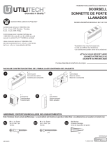
NEW INSTALLATION WIRING
WARNING: Turn power off at fuse or
circuit breaker before installing
transformer. Follow all national and
local codes.
1. Mount Transformer: Transformers
should be mounted on or near a
junction box. They can also be
mounted to the electrical service
panels. Junction boxes in utility
rooms, crawl spaces, or basements
are preferred. Avoid attic locations.
2. Install 16 Volt, 10 Watt transformer
according to the instructions supplied
with transformer.
Note:
For multiple
mechanical chimes, use a 16 Volt,
15 Watt transformer. Failure to use
a transformer with adequate power
will result in loss of sound or may re-
sult in the system being inoperative.
3. Run two No. 20 AWG or better bell
wires (Heath
®
/Zenith No. 196C or No.
199C accessory wire) to the chime
location. Strip away 1/2" of insulation
from end of wires. Connect each wire
to transformer (see Figure 1).
4. Label Transformer Wires: Using masking tape or wire tags provided on packaging, label one
wire “T” and the other “C”.
FRONT
TRANS
REAR
FRONT
REAR
TRANS
DO NOT OIL
Figure 1
Front Push Button
Rear Push Button
(If Applicable)
Optional Second Mechanical Chime
Transformer
Cover Pin
MOUNTING SUGGESTIONS
• Power must be supplied from a 16 Volt, 10 Watt transformer or 16 Volt, 15 Watt transformer
(Heath
®
/Zenith models 122C, 121AC, or 125C).
•Mount door chime in a central location so it can be heard throughout the home.
• See actual unit for orientation of base.
• Use wall anchors if not mounting directly to wall stud.
• Use mounting holes located on both sides of base.
• Route wires through wire entrance holes (see Figure 1).
Wire Nut
Mounting
Slot
Wire Entrance
Holes
Mounting
Hole
Base Style “A” Base Style “B”
Hardwired Mechanical Chimes

-2-
598-1112-01
REPLACEMENT INSTALLATION WIRING
For replacing an existing transformer, follow step 2 above.
WARNING: Turn power off at fuse or circuit breaker before installing transformer.
1. Verify existing chime/bell system works correctly. If no sound is heard, see Troubleshooting
section for more information.
2. Check transformer power rating. This chime requires a minimum 16 Volt, 10 Watt transformer.
3. Remove cover from existing chime and disconnect wires from terminal screws. Using masking
tape or wire tags provided on packaging, label all wires (“F”-Front Push Button, “T”-Transformer,
“R”-Rear Push Button) as you remove them according to terminal markings.
4. Remove existing chime base from wall.
5. Route wires through wire entrance hole(s) in new chime base.
6. Mount chime base to wall using screws provided.
7. Connect wire “F” to the screw terminal marked “FRONT”. Connect wire “T” to screw terminal
marked “TRANS”. Connect wire “R” to screw terminal marked “REAR” (see Figure 1).
Note:
The
common connection may exist elsewhere in the original installation and may not be visible.
8. Place chime cover securely over base.
9. Restore power. Press push button(s) to test chime.
Note: For multiple mechanical chimes, use a 16 Volt, 15 Watt transformer.
HELPFUL HINTS
• Electrical work must be in accordance with national and local electrical codes. If in doubt,
consult a qualified electrician. Turn power off at fuse or circuit breaker before installing/
replacing transformer.
•Many chimes, bells, and buzzers are installed with a 10 Volt, 5 Watt transformer. This chime
requires a minimum 16 Volt, 10 Watt transformer.
• For replacement installation, identify and tag wires before removing them according to terminal
markings: “F”-Front Push Button, “R”-Rear Push Button, and “T”-Transformer.
• For new installations install #20 AWG bell wire in pairs from push button(s) and transformer to
chime. Do not pinch wire or damage its insulation. Heath
®
/Zenith accessory wire (No. 196C or
No. 199C) is available for chime installations.
• Clean wood, plastic, and metal parts with mild soap and warm water. Never use cleaners or
polishes. Never use any fluids on the mechanical chime mechanism.
5. Mount push button(s) to door frame(s). Run two No. 20 AWG bell wires from push button(s) to
the chime location. Strip away 1/2" of insulation from end of wires. Connect each wire to push
button(s) (see Figure 1).
Label Front Push Button Wires: Using masking tape or wire tags provided on packaging, label
one wire “F” and the other “C”.
Label Rear Push Button Wires: Using masking tape or wire tags provided on packaging, label
one wire “R” and the other “C”.
6. At the chime, pull all wires through wall cavity and out through a 1/2" hole in the wall board.
Route wires through wire entrance hole(s).
7. Mount chime base to wall using screws provided.
8. Strip away 1/2" of insulation from end of wires. Connect wire “F” to the screw terminal marked
“FRONT”. Connect wire “T” to screw terminal marked “TRANS”. Connect wire “R” to screw ter-
minal marked “REAR” (see Figure 1).
9. Twist together the wires labeled “C” and secure them with a UL approved wire nut.
10.Place chime cover securely over base.
11. Restore power. Press push button(s) to test chime.

-3-
598-1112-01
TROUBLESHOOTING
Chime does not sound:
• Check Chime: Disconnect wire from terminal marked “TRANS”. Have someone operate push
button at front door while you momentarily touch the “TRANS” wire to terminal marked “FRONT”.
You will see a small spark if push button, wiring, and transformer are operating properly. Repeat
the steps for “REAR” terminal and rear push button. If wiring between transformer and push
button(s) check out properly, replace chime.
• Check Transformer: Momentarily touch the two low-voltage terminals with a screwdriver. You will
see a small spark if transformer is operating properly. If no spark is evident, replace transformer.
• Check Push Button(s): Remove suspected unit from door frame, disconnect wire from terminals
and touch bare wires together. If chime operates, push button is defective. Replace push button.
DESA Specialty Products™ reserves the right to discontinue and to change specifications at any time
without notice without incurring any obligation to incorporate new features in previously sold products.
ONE YEAR LIMITED WARRANTY
This is a “Limited Warranty” which gives you specific legal rights. You may also have other rights which vary from
state to state or province to province.
For a period of one year from the date of purchase, any malfunction caused by factory defective parts or workmanship
will be corrected at no charge to you. To obtain a refund or a replacement, return the product to the place of purchase.
Not Covered - Repair service, adjustment and calibration due to misuse, abuse or negligence, and expendable
items are not covered by this warranty. Unauthorized service or modification of the product or of any furnished
component will void this warranty in its entirety. This warranty does not include reimbursement for inconvenience,
installation, setup time, loss of use, or unauthorized service.
This warranty covers only DESA Specialty Products™ assembled products and is not extended to other
equipment and components that a customer uses in conjunction with our products.
THIS WARRANTY IS EXPRESSLY IN LIEU OF ALL OTHER WARRANTIES, EXPRESS OR IMPLIED,
INCLUDING ANY WARRANTY, REPRESENTATION OR CONDITION OF MERCHANT ABILITY OR THAT
THE PRODUCTS ARE FIT FOR ANY PARTICULAR PURPOSE OR USE, AND SPECIFICALLY IN LIEU OF ALL
SPECIAL, INDIRECT, INCIDENTAL, OR CONSEQUENTIAL DAMAGES.
REPAIR OR REPLACEMENT SHALL BE THE SOLE REMEDY OF THE CUSTOMER AND THERE SHALL BE
NO LIABILITY ON THE PART OF DESA SPECIALTY PRODUCTS™ FOR ANY SPECIAL, INDIRECT,
INCIDENTAL, OR CONSEQUENTIAL DAMAGES, INCLUDING BUT NOT LIMITED TO ANY LOSS OF
BUSINESS OR PROFITS, WHETHER OR NOT FORESEEABLE. Some states or provinces do not allow the
exclusion or limitation of incidental or consequential damages, so the above limitation or exclusion may not apply
to you. Retain receipt for warranty claims.
No Service Parts Available for this Product
TECHNICAL SERVICE
(Do Not Send Products)
If you experience a problem, follow this guide. You may also want to visit our Web site at:
www.desatech.com. If the problem persists, call* for assistance at 1-800-858-8501, 7:30 AM to 4:30
PM CST (M-F). You may also write* to:
DESA Specialty Products™
P.O. Box 90004, Bowling Green, KY 42102-9004
ATTN: Technical Service Specialty Products
* If contacting Technical Service, please have the following information available: Model Number,
Date of Purchase, and Place of Purchase.

-11-
598-1112-01
Notes/Notas ___________________________________
_____________________________________________
_____________________________________________
_____________________________________________
_____________________________________________
_____________________________________________
_____________________________________________
_____________________________________________
_____________________________________________
_____________________________________________
_____________________________________________
_____________________________________________
_____________________________________________
_____________________________________________
_____________________________________________
_____________________________________________
_____________________________________________
_____________________________________________
_____________________________________________
_____________________________________________
_____________________________________________
_____________________________________________
_____________________________________________
_____________________________________________
_____________________________________________
_____________________________________________
_____________________________________________
_____________________________________________
_____________________________________________

-12-
598-1112-01
Notes/Notas ___________________________________
_____________________________________________
_____________________________________________
_____________________________________________
_____________________________________________
_____________________________________________
_____________________________________________
_____________________________________________
_____________________________________________
_____________________________________________
_____________________________________________
_____________________________________________
_____________________________________________
_____________________________________________
_____________________________________________
_____________________________________________
_____________________________________________
_____________________________________________
_____________________________________________
_____________________________________________
_____________________________________________
_____________________________________________
_____________________________________________
_____________________________________________
_____________________________________________
_____________________________________________
_____________________________________________
_____________________________________________
_____________________________________________
/