Page is loading ...

Two-Note, Single
Entrance Chime
Battery or Transformer Operated
Model 23/M
This package includes (Style of chime may vary from illustration):
• Chime
• Mounting Screws
• Instructions
New installations require:
• Push Button (Non-Lighted)
• 4 - “C” Batteries or 1 - 8/10V Transformer
• #20 AWG Bell Wire (such as Heath
®
/Zenith 196C or 199C)
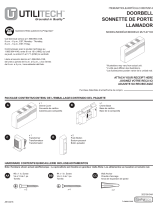
MOUNTING THE CHIME
Position chime at eye level in desired room. Sound
travels farthest with the fewest obstacles. Do not place
over heat source; i.e., radiator, heater, or stove.
At the chosen location drill two small pilot holes
3
1
/
4
" apart in the vertical plane. The chime cover
is a push fi t onto the base. Remove chime cover
to expose base. Position base and mount in place
using screws supplied, key-hole shaped slot at the
top (see Figure 1).
WIRING THE CHIME
A. Battery Operation. Do not use with lighted push
button. Fit (4) “C” batteries noting + or - marked on
the base plate. Alkaline batteries offer longer life.
Batteries are not included.
To connect bell wire from chime to push button, cut
it to required length, strip back outer coating 1/2",
wrap exposed wire around chime terminals #1 and
#2 only and tighten screws. NOTE: No connection
to chime terminal #3 (see Figure 2).
B. For Transformer Operation Only.
WARNING: Turn off housepower before start-
ing installation. Failure to do so may result in
danger from electric shock.
Connect chime terminals #1 and #3 to the low
voltage terminals of an 8V or 10V transformer
(Heath
®
/Zenith 107C or 125C) using #20AWG bell
wire (see Figure 3).
1
3
2
Figure 1
Base
Plate
Chime
Cover
1
3
2
Figure 2 - Battery Operation
To Push Button
1
3
2
Figure 3 - Transformer
Operation
To Push Button
To 8/10V
Transformer
© 2007 HeathCo LLC 598-1134-02

-2-
598-1134-02
Transformers should be mounted on or near a junction box. They can also be mounted
to the electrical service panels. Junction boxes in utility rooms, crawl spaces, or
basements are preferred. Avoid attic locations whenever possible.
To install a new transformer, TURN OFF HOUSE POWER, then mount either
Heath
®
/Zenith 107C or 125C transformer to a convenient junction box or circuit
breaker box. Follow instructions supplied with transformer.
To connect bell wire from chime to push button, cut it to required length, strip coat-
ing 1/2", wrap exposed wire around chime terminals #1 and #2 and tighten screws
(see Figure 3).
Replace cover and turn house power back on. Run bell wire to push button location
and connect to push button. Follow instructions supplied with push button.
C. Replace Existing Transformer-Operated Chime Using Battery Operated
Chime With Existing Wiring. (Do not use with lighted push button.)
TURN OFF HOUSE POWER. Label wires at the
“old” chime as shown in Figure 4. Remove “old”
chime. At the transformer remove the two or three
low voltage wires from the output terminals, twist
them together and secure them with a wire nut.
Turn the house power back on. Mount the new
battery-operated chime in place of the “old” chime
and connect wires as follows: F to chime terminal
#1; R to chime terminal #1 (NOTE: Rear door and
front door will both sound the two-note (Ding-Dong)
tune when either button is activated.); T to chime
terminal #2. NOTE: No connection to chime terminal
#3 (see Figure 5). Fit (4) “C” batteries noting + or
- marked on the base plate. Alkaline batteries offer
longer life. Batteries are not included.
REAR
TRANS
FRONT
F
R
T
Figure 4 - “Old Chime”
To Push Button
3
2
F
T
1
R
Figure 5
/