Page is loading ...

Printed in U.S.A.
8/06 8000842-01 Rev B
Assembly Instructions
8000842-01
Type 960 Class I & II .96 Meter Antenna System
Type 123 Class I & II 1.2 Meter LFL Antenna System
with Factory Assembled Az/El Cap Mount
Andrew Corporation
3 Westbrook Corporate Center
Suite 900
Westchester, Illinois 60154 USA
Customer Support Center
From North America
Telephone: 1-800-255-1479
Fax: 1-800-349-5444
satcom@andrew.com
One Company. A World of Solutions.
International
Telephone: +1-708-873-2307
Fax: +1- 708-349-5444
Internet: www.andrew.com
DO NOT DISCARD CONTENTS
The product in this packaging was placed in the market after August 13, 2005. Its components must not be discarded with
normal municipal or household waste.
Contact your local waste disposal agency for recovery, recycling, or disposal instructions.

VSAT ANTENNA/MOUNT/LNB
LIMITED TWELVE (12) MONTH WARRANTY
This ANDREW CORPORATION
®
equipment is warranted to be free from defects in material and workmanship
under normal use and service. ANDREW shall repair or replace defective equipment, at no charge, or at its option,
refund the purchase price, if the equipment is returned to ANDREW not more than twelve (12) months after ship-
ment. Removal or reinstallation of equipment and its transportation shall not be at the cost of ANDREW except
ANDREW shall return repaired or replaced equipment freight prepaid.
This Warranty shall not apply to equipment which has been repaired or altered in any way so as to affect its
stability or durability, or which has been subject to misuse, negligence or accident. This Warranty does not cover
equipment which has been impaired by severe weather conditions such as excessive wind, ice, storms, lightning,
or other natural occurrences over which ANDREW has no control, and this Warranty shall not apply to equipment
which has been operated or installed other than in accordance with the instructions furnished by ANDREW.
Claimants under this Warranty shall present their claims along with the defective equipment to
ANDREW immediately upon failure. Non-compliance with any part of this claim procedure may
invalidate this warranty in whole or in part.
THIS WARRANTY IS EXPRESSLY IN LIEU OF ALL OTHER AGREEMENTS AND WARRANTIES, ANY IMPLIED
WARRANTY OF MERCHANTABILITY OR FITNESS FOR A PARTICULAR PURPOSE IS LIMITED IN DURATION TO
THE DURATION OF THIS WARRANTY. ANDREW DOES NOT AUTHORIZE ANY PERSON TO ASSUME FOR IT THE
OBLIGA
TIONS CONT
AINED IN
THIS
W
ARRANTY AND
ANDREW
NEITHER ASSUMES NOR AUTHORIZES ANY
REPRESENT
A
TIVE OR OTHER PERSON TO ASSUME FOR IT ANY OTHER LIABILITY IN CONNECTION WITH
THE EQ
UIPMENT DELIVERED OR PR
O
VIDED
.
IN NO EVENT SHALL ANDREW BE LIABLE FOR ANY LOSS OF PROFITS, LOSS OF USE,
INTERR
UPTION OF B
USINESS
, OR INDIRECT
, SPECIAL OR CONSEQ
UENTIAL DAMAGES OF ANY KIND.
In no e
v
ent shall
ANDREW
be liab
le f
or damages in an amount greater than the purchase price of the equipment.
Some states do not allow limitations on how long an implied warranty lasts, or allow the exclusion or
limitation of incidental or consequential damages
, so the above limitations or exclusions may not apply to you.
1
DATE DESCRIPTION REV.
1/06 ECN9007200 Rev A
8/06 ECN9007484 Rev B
16
HARDWARE SORTER
BOLT, PLOW, SPECIAL M8 x 1.25 x 56
I
TEM 1
BOLT, PLOW, SPECIAL M8 x 1.25 x 91 SHEET # 14
ITEM 1
BOLT, HEX HEAD M6 x 16
ITEM 19
BOLT, HEX HEAD M6 x 20
ITEM 3
BOLT, RD, HD, SQ NK M6 x 22
ITEM 6
BOLT, RD, HD, SQ NK M6 x 55
ITEM 17
BOLT, HEX HEAD M8 x 20
ITEM 26

IMPORTANT!!!
INST
ALLATION OF THIS PRODUCT SHOULD BE PERFORMED ONLY BY A PROFESSIONAL INSTALLER AND
IS NOT RECOMMENDED FOR CONSUMER D.I.Y. (DO-IT-YOURSELF) INSTALLATIONS.
DANGER!!!
WATCH FOR WIRES! YOU CAN BE KILLED IF THIS PRODUCT COMES NEAR POWER LINES. Installation of this product near power lines is dan-
gerous. For your own safety, follow these important safety rules.
1. Perform as many functions as possible on the ground.
2. Watch out for overhead power lines. Check the distance to the power lines before starting installation.
We recommend you stay a minimum of 6 meters (20 feet) from all power lines.
3.
Do not use metal ladders.
4. Do not install antenna or mast assembly on a windy day.
5. If you start to drop antenna or mast assembly, get away from it and let it fall.
6. If any part of the antenna or mast assembly comes in contact with a power line, call your local power company.
DO NOT TRY TO REMOVE IT YOURSELF! They will remove it safely.
7. Make sure that the mast assembly is properly grounded.
WARNING!!!
Assembling dish antennas on wind
y days can be dangerous. Because of the antenna surface, even slight winds create strong forces. For
example, a 1.0m antenna facing a wind of 32 km/h (20 mph) can undergo forces of 269 N (60 lbs). Be prepared to safely handle these forces at
unexpected moments. Do not attempt to assemble, move or mount a dish on windy days or serious, even fatal accidents may occur.
Andrew Corporation
®
is not responsible or liable for damage or injury resulting from antenna installations.
Antennas improperly installed or installed to an inadequate structure are very susceptible to wind damage. This damage can be very serious or even
life threatening. The owner and installer assumes full responsibility that the installation is structurally sound to support all loads (weight, wind & ice)
and properly sealed against leaks. Andrew will not accept liability for any damage caused by a satellite system due to the many unknown variable
applications.
The first and most important consideration when
choosing a prospectiv
e antenna site is whether or not the
area can provide an acceptable “look angle” at the
satellites. A site with a clear, unobstructed view is preferred.
Also consider obstr
uction that may occur in the future such
as the g
rowth of trees. Your antenna site must be selected in
advance so that you will be able to receive the strongest
signal a
vailable. To avoid microwave interference, obstruc-
tions, etc. conduct an on-site survey with a portable antenna.
As with any other type of construction, a local building
permit may be required before installing an antenna. It is the
property owner’s responsibility to obtain any and all permits.
Before any digging is done, information regarding the possi-
bility of underg
round telephone lines, power lines, storm
drains, etc. in the excavation area should be obtained from
the appropriate agency.
Because soils vary widely in composition and load capacity,
consult a local prof
essional engineer to deter
mine the
appropriate foundation design and installation procedure. A
suggested foundation design with conditions noted is included
in this manual for reference purposes only.
2
ASSEMBLY TOOLS REQUIRED
1 - Compass 1 - 10mm Nut Driver 1 - 13mm Deep Socket (³⁄₈” Drive)
1 - Clinometer 1 - 10mm Socket (
³⁄₈” Drive) 1 - 9” Magnetic Level
1 - Ratchet Wrench (
³⁄₈” Drive) 1 - Phillips Screwdriver (#1 or #2) 1 - 13mm Combination Wrench
1- Torque Wrench 1 - 10mm Combination Wrench
PREINSTALLATION MATERIALS CHECKLIST
Grounding Rod Clamp & Grounding Bloc
k - As Required b
y National Electr
ic Code or local codes
.
Ground Wire - #10 solid copper as or required by National Electric Code or local codes (length required).
Concrete - (See Ground Pole section for quantity and grade).
#3 Rebar - (See Ground P
ole section f
or quantity).
Deformed steel per ASTM A615, grade 40 or 60.
SITE SELECTION
QTY.
NO
.
DESCRIPTION
96cm
1.2m
1 BOLT, PLOW, SPECIAL, M8 x 1.25 x 56 mm 2 -
BOLT, PLOW, SPECIAL, M8 x 1.25 x 91 mm 2 4
2 REFLECTOR, .96m 1 1
REFLECTOR, 1.2m LFL 1 1
3 BOLT, HEX HD, SS, M6 x 1.0 x 20mm 4 4
4 WASHER, LOCK, SS, M8 4 4
5 NUT, HEX HD M8 x 1.25 4 4
6 BOLT, RD HD SQ NK M6 x 1.0 x 22mm 1 5
7 PLATE, EXTENSION - 1
8 WASHER, LOCK, SS, M6 (Light Duty) 5 5
WASHER, LOCK, SS, M6 (Medium Duty) 7 9
9 NUT, HEX HD, M6 x 1.0 (Light Duty) 3 3
NUT, HEX HD, M6 x 1.0 (Medium Duty) 5 7
10 BRACE, R.H. .96m AZ/EL MT 1 -
BRACE, 1.2m LFL AZ/EL (Medium Duty) - 2
11 BRACE, L.H. .96m AZ/EL MT 1 -
12 WASHER, EXT
T
OO
TH LOCK, M6
2
2
15
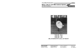
PARTS LIST
CLASS I - LIGHT DUTY SYSTEM
(1.2m SHOWN)
C
LASS II - MEDIUM DUTY SYSTEM
(1.2m SHOWN)
96cm CLASS II - MEDIUM DUTY
F
EED
ASSEMBLY
FEED
ASSEMBLY
2
5
2
4
23
2
0
3
9
2
1
20
8
9
1
8
19
18
18
16
15
6
13
8
9
4
5
9
13
12
10
9
8
6
7
6
4
3
5
14
19
8
2
0
3
10
11
1
2
1
3
9
6
1
5
8
3
8
21
19
8
2
2
9
9
26
QTY
.
NO. DESCRIPTION 96cm 1.2m
13
W
ASHER, FLA
T
, SS, M6 (Medium Duty) 3 3
14
MOUNT ASSEMBLY, 1.2m LFL (Light Duty) 1 1
15 NUT, M6 x 1.0, ESNA 1 1
16
“U”
CUP
, BOOM
-
1
17 BOLT, RD HD SQ NK, M6 x 1.0 x 55mm 1 1
18 FEED SUPPORT (Medium Duty) 1 -
FEED SUPPORT (Medium Duty) - 1
19 BOLT, HEX HD, SS, M6 x 1.0 x 16mm (Light Duty) 3 3
BOLT, HEX HD, SS, M6 x 1.0 x 16mm (Medium Duty) 4 4
20
SIDE FEED LEG, .96m ANTENNA
2
-
SIDE FEED LEG, 1.2m, ANTENNA - 2
21 BOTTOM FEED LEG (.96m Light Duty) 1 -
BO
TT
OM FEED LEG (1.2m Light Duty)
-
1
22
TERMINAL, FEED SUPPOR
T (Light Duty)
1
1
23 CLAMP, MTG BLOCK (Light Duty) 1 1
24 WASHER, FLAT M6 (Light Duty) 2 2
25 BOLT, HEX HD, M6 x 1.0 x 30mm 2 2
26 BOLT, HEX HD, M8 x 1.25 X 20mm 2 2

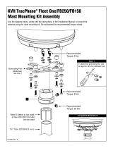
GROUND POLE INSTALLATION (96cm System)
M
IN.
D
IA.
d
d
MIN.
DIA.
ANT
2.88" or
3.00" O.D.
2.88" or
3.00" O.D.
40"
C
L
72"
36.4"
36.4"
i
ncreased,
72"
41.5"
5
0" depth may be
w
ill increase
l
ength of rebar
c
oncrete and
accordingly.
2"
2"
50"
NOTE:
#3 REBAR x DIA. OF PIER, INSERT
FROST LINE
#3 REBAR x
DIA. OF PIER
INSERT THRU HOLE
IN TUBE & CENTER
AT 90
o
APART
(SEE NOTE)
(4)#3x24"MIN.
BELOW
THRU HOLE IN TUBE & CENTER
1" to 2"
WATER RUN OFF
GRADE
SLOPE FOR
BELOW
FROST LINE
APPROX.
1" to 2"
SLOPE FOR
(SEE
NOTE)
GRADE
WATER RUN OFF
GROUND
ANT WIND VEL. DIM “d” CONC VOL. DIM “d” CONC VOL. DIM “d’ CONC VOL. DIM “d” CONC VOL. POLE
80 MPH 7” 0.9 10” 1.8 7” 1.2 7” 1.2 “A”
90 MPH 8” 1.2 13” 3.0 7” 1.2 8” 1.5
96cm 100 MPH 10” 1.8 15” 4.0 7” 1.2 10” 2.4 “A” or
110 MPH 11” 2.2 17” 5.2 7” 1.2 11” 2.9 “B”
125 MPH
14”
3.5 20” 7.2 9” 1.9 14” 4.7 “B” Only
POLE SPECIFICATIONS:
Ground P
ole
“A”
= 3.00 O
.D. x 10 G.A. x 72” Steel
Ground Pole “B” = 2
⁷⁄₈ O.D. x .203 Wall x 72” Steel ASTM 120 Mech Tubing (2¹⁄₂ Sch. 40)
NOTE:
Pole not supplied and must be field drilled ⁵⁄₈” dia. for #3 rebar and drilled .218 for ¹⁄₄-20 self tapping grounding
scre
w (see P
age 7) and galv
aniz
ed or painted f
or protection.
1 - P
ole and foundation design based on the following criteria:
a) Uniform building code exposure B or C and 1.5 stability factor.
b) Vertical soil pressure of 2000 pounds per square foot.
c)
Later
al soil pressure of 400 pounds per square f
oot.
d)
Concrete compressive strength of 2500 pounds per square inch in 28 days.
2 -
CAUTION - The foundation design shown does not represent an appropriate design for any specific locality since soil conditions vary
and may not meet design cr
iter
ia giv
en in Note 1. You should consult a local professional engineer to determine your soil conditions
and appropriate f
oundation.
Exposure “B” Exposure “C” Exposure “B” Exposure “C”
PIER FOUNDATIONS DEEP FROST LINE FOUNDATIONS
Bubble
Level
Ground Pole
Must Be
Vertical In
All Directions
Within .19 Inches
At Top (0.3ß)
STANDARD
PIER FOUNDATION
DEEP FROST
LINE FOUNDATION
3
AZ-EL MOUNT WITH M8 INSERT AND SET SCREW
IMPORTANT
M8 x 20 mm Hex Head Set Screws are recommended for schedule 40 (.203 wall) mast and
NOT RECOMMENDED for mast with a wall thickness less than 10 ga (.134) such as
Non-Penetrating Roof Mounts and Roof/Wall Mounts.
Once fine tuning is complete and all Clamp Bolts are equally torqued to 18 ft-lbs. in
accordance with 8000842 manual, then install the two M8 x 20 mm Hex Head Set Screws
supplied. Install one in each clamp half as shown in Fig. 1.0. Torque each M8 x 20 mm
Hex Head Screw to 15 ft-lbs. Repeat torque to insure 15 ft-lbs. has been reached on both
screws.
See Manual 8000842 for additional instructions not shown here.
Clamp Bolts
M8 x 20 mm
Hex Head
Set Screw
M8 Insert
Half Clamp
14
Figure 1.0 (AZ-EL Mount with M8 Insert and Set Screw)

GROUND POLE INSTALLATION (1.2m System)
4
MIN.
DIA.
d
d
MIN.
DIA.
ANT
2.88" or
3.00" O.D.
2.88" or
3.00" O.D.
40"
C
L
72"
35.8"
35.8"
increased,
72"
40.9"
5
0" depth may be
w
ill increase
length of rebar
concrete and
a
ccordingly.
2"
2"
50"
NOTE:
#3 REBAR x DIA. OF PIER, INSERT
FROST LINE
#3 REBAR x
DIA. OF PIER
INSERT THRU HOLE
IN TUBE & CENTER
AT 90
o
APART
(SEE NOTE)
(4)#3x24"MIN.
BELOW
T
HRU HOLE IN TUBE & CENTER
1" to 2"
WATER RUN OFF
GRADE
SLOPE FOR
BELOW
FROST LINE
APPROX.
1" to 2"
SLOPE FOR
(SEE
NOTE)
GRADE
WATER RUN OFF
GROUND
ANT WIND VEL. DIM “d” CONC VOL. DIM “d” CONC VOL. DIM “d’ CONC VOL. DIM “d” CONC VOL. POLE
80 MPH 8” 1.3 13” 3.4 8” 1.6 10” 2.5 “A” or
90 MPH 10” 2.0 16” 5.1 8” 1.6 12” 3.6 “B”
1.2M 100 MPH 12” 2.9 18” 6.5 8” 1.6 13” 4.2 “B” or
LFL 110 MPH 14” 3.9 21” 8.8 10” 2.5 16” 6.4 “C”
125 MPH
17”
5.8 24” 11.5 12” 3.6 19” 9.0 “D”
POLE SPECIFICATIONS:
Ground P
ole
“A”
= 2.88 O
.D. x .154 Wall (Sch 40) x 72” ASTM A53 or A501 Pipe
Ground P
ole
“B” = 3.00 O.D. x 9 Ga. (.148 Wall) x 72” Steel - CM PN 611685101
Ground Pole “C” = 2.88 O.D. x 2.88 O.D. x .276 Wall (Sch 80) x 72” Steel ASTM A53 or A501 Pipe
Ground Pole “D” = 3.00 O.D. x .250 Wall x 72” Steel ASTM 120 Mech Tubing
NOTE
:
Pole “B” is supplied from factory powder painted and with hole for #3 rebar and grounding screw.
Poles “A”, “C” and “D” are not supplied and must be field drilled
⁵⁄₈” dia. for #3 rebar and drilled .218
f
or
¹⁄₄-20 self tapping g
rounding scre
w and galvanized or painted for protection.
1 - P
ole and f
oundation design based on the f
ollowing criteria:
a)
Uniform building code exposure B or C and 1.5 stability factor.
b) Vertical soil pressure of 2000 pounds per square foot.
c) Lateral soil pressure of 400 pounds per square foot.
d)
Concrete compressiv
e strength of 2500 pounds per square inch in 28 da
ys
.
2 -
CAUTION - The foundation design shown does not represent an appropriate design for any specific locality since soil conditions vary
and may not meet design criteria given in Note 1. You should consult a local professional engineer to determine your soil conditions
and appropriate foundation.
Exposure “B” Exposure “C” Exposure “B” Exposure “C”
PIER FOUNDATIONS DEEP FROST LINE FOUNDATIONS
Bubble
Level
Ground Pole
Must Be
Vertical In
All Directions
Within .19 Inches
At Top (0.3ß)
13
M
o
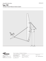
Based on 40.9" (1039 mm) from Mounting Surface of Center Line of Antenna
Values shown represent maximum forces for any wind direction and
include 1.5 F
s
. Height and exposure factors from uniform building code
are NOT included.
APPENDIX B
1.2m Antenna Survival Windloads at 125 MPH Velocity
BEAM AXIS
MECHANICAL AXIS
(NORMAL TO ANTENNA FACE)
16.97
o
OFFSET
40.9" HEIGHT
(1039 mm)
F
H
M
T
F
V
F
H
= Horizontal Force
F
V
= Vertical Force
M
T
= Torsional Moment
M
O
= Overturning Moment
M
O
ELEVATION DEGREES
MECHANICAL BEAM
0 17
10 27
20 37
30 47
40 57
50 67
60 77
70 87
FORCE (POUNDS)
F
H
F
V
1285 -35
1217 -257
1182 -497
1071 -711
943 -857
822 -943
686 -985
515 -762
MOMENTS (FT-LBS/N-m)
M
T
M
O
500 4,380
488 4,148
464 4,029
421 3,650
357 3,214
299 2,802
232 2,338
178 2,096

ASSEMBLY AND INSTALLATION
INSTALLING AZ/EL CAP MOUNT ONTO POLE
The AZ/EL Cap is factory preassembled, therefore, no
assemb
ly is required. Before installing AZ/EL Cap onto
ground pole, a concrete foundation should be in place
and cured.
MODEL 611612001 (Fine Tune Option)
Loosen (8) Carriage Bolts and nuts securing the “U”
Bracket to the Top Bracket and “U” Bracket to (2) half
clamps and swivel nut, hex nut (for optional fine tune fea-
ture). (Ref. Fig. 1.0). Install AZ/EL Cap Mount onto
Ground Pole. Equally tighten (4) Clamp Bolts so that
Cap is held stationary on Ground Pole, but can be
swiveled with slight pressure (approximately 2 ft-lbs (2.7
N-m). Retighten and torque (4) Carriage Bolts and nuts
securing “U” bracket to half clamps to 18 ft-lbs (24.4 N-
m). Leave loose (4) Carriage Bolts and Swivel Nut, Hex
Nuts, for fine tune option.
MODEL 611612002 (w/o Fine Tune Option)
Make sure (4) carriage bolts and nuts securing the
(2) Half Clamps to top bracket are loose.
(Ref. Fig.
1.1) Place AZ/EL Cap onto Ground Pole and tighten (4)
Half Clamp Bolts to approximately 2 ft-lbs (2.7 N-m) (just
enough to allow AZ Clamp to turn on pole with slight
pressure). Tighten and torque (4) Carriage Bolts and
Nuts in Top Bracket to 18 ft-lbs (24.4 N-m) (loosened
above).
ASSEMBLING REFLECTOR ONTO AZ/EL CAP MOUNT
96cm System
Install two M8 x 56 (56 mm) Plow Bolts into holes in
Reflector Face and two (91 mm) into bottom holes.
Lift Reflector and insert exposed portion of bolt into
holes into Antenna Br
ac
ket Flange. Install 4 Lock
Washers and Hex Nuts on bolts. (Ref. Fig. 1.2)
1.2m System
Install four M8 x 91 (91 mm) Plow Bolts into top holes
in Reflector Face. Lift Reflector and insert exposed
portion of bolt to holes in Antenna Bracket Flange.
Install 4 Lock Washers and Hex Nuts on bolts. (Ref.
Fig.
1.2)
Assemble Extension Plate to AZ/EL Housing using
two M6 x 22mm Round Head Square Neck Bolts,
Lock Washers, and Hex Nuts. (Ref. Fig. 1.3) Tighten
and torque to 6 ft-lbs (8 N-m).
Tighten and torque Reflector bolts to 11 ft-lbs (15 N-m).
IMPORTANT: Note or
ientation of bolt holes in Reflector
Flange. Holes should be located on each side and bot-
tom of the Reflector as shown in Figure 1.2.
T
OP BRACKET
"U" BRACKET
HEX NUT,
CARRIAGE BOLT (8)
H
ALP CLAMP (2)
CLAMP BOLTS
(
CARRIAGE BOLT &
HEX NUT) (4)
HEX NUT
S
WIVEL NUT
FIG. 1.0 - Model 611612001 AZ/EL w/Fine Tune
Option
(2 REQ)
PLOW BOLT
M8 x 1.25 x 56
(.96m ONLY)
(2 REQ) .96m
PLOW BOLT
M8 x 1.25 x 91
(QTY. 4, 1.2m)
SIDE BOLT
HOLE
BOTTOM
BOLT
HOLE
GROUND
POLE
CLAMP
BOLTS
HEX NUT
(4 REQ)
LOCK WASHER
(4 REQ)
MOUNT ASSEMBLY
FIG. 1.2 - Assembling Reflector to AZ/EL Mount
and Ground Pole (.96cm Shown)
CLAMP BRACKET
H
EX NUT,
CARRIAGE BOLT (4)
HALF CLAMP (2)
CLAMP BOLTS
(CARRIAGE BOLT &
H
EX NUT (4)
FIG. 1.1 - Model 611612002 AZ/EL w/o Fine
Tune Option
5
APPENDIX A
96cm Antenna Survival Windloads at 125 MPH Velocity
M
o
Based on 41.5" (1054 mm) from Mounting Surface of Center Line of Antenna
Values shown represent maximum forces for any wind direction and
include 1.5 F
s
. Height and exposure factors from uniform building code
are NOT included.
F
H
= Horizontal Force
F
V
= Vertical Force
M
T
= Torsional Moment
M
O
= Overturning Moment
BEAM AXIS
MECHANICAL AXIS
(NORMAL TO ANTENNA FACE)
15.4
o
OFFSET
41.5" HEIGHT
(1054 mm )
F
H
M
T
F
V
M
O
ELEVATION DEGREES
MECHANICAL BEAM
0 15
10 25
20 35
30 45
40 55
50 65
60 75
70 85
FORCE (POUNDS)
F
H
F
V
747 -20
707 -150
687 -289
622 -413
548 -498
478 -548
398 -573
299 -443
MOMENTS (FT-LBS/N-m)
M
T
M
O
150 2584
147 2445
139 2376
126 2151
107 1896
90 1653
70 1377
54 1034
12

6
ASSEMBLY AND INSTALLATION
FEED AND FEED LEG INSTALLATION
NOTE: Long formed end of Side Feed Leg attaches to
the Reflector rim, short formed to side of Feed Support
Terminal.
Assemble Bottom Feed Leg to bottom of Reflector rim.
From the inside of Reflector rim, insert M6 x 16mm Hex
Bolt thru hole in rim and attach Bottom Feed Leg. Secure
with Lock Washer and Hex Nut.
NOTE: Bottom Feed Leg is the one with slight bend, with
lance, on one end, and is shorter than the Side Feed
Legs.
Leave all hardware loose. Insert Bottom Feed Leg end
with lance into socket hole in center of Feed Support
Terminal. Twist to engage lances. Attach left and right
Feed Support Legs to Feed Support Terminal, securing
with M6 x 16mm Hex Bolts and Lock Washers. Refer to
Instruction for Feed Assembly to assemble Feed
Assembly and ODU to Terminal Block. Tighten and
torque all hardware to Terminal Block and Reflector to
4 ft-lbs (5.4 N-m). Tighten two screws in Terminal Block
socket equally.
FEED AND FEED SUPPORT TUBE INST
ALLATION
MEDIUM DUTY
Assemble “U” Clip to bottom of Reflector using M6 x
22mm Round Head Square Neck Bolt, Lock Washer and
Hex Nut. Insert bottom Feed Support Tube into “U” Clip
and secure with M6 x 55mm Round Head Square Neck
Bolt and elastic Lock Nut. (Ref. Fig. 1.5 & 1.6) Assemble
Feed Support Block (supplied with Feed package) to
Feed Support Tube, using two M6 x 16mm Hex Bolts and
Lock Washers.
96cm System (Ref. Fig. 1.5)
Attach Side Feed Legs and Braces to left and right
sides of Reflector using M6 x 20mm Hex Bolts, Lock
Washers and Hex Nuts. (NOTE: Long formed end of
F
eed Leg attaches to Reflector
.
Short formed end of
Brace attaches to inside of Reflector rim.) Attach flat-
ten end of Brace to top of Mount Housing using M6 x
22mm Round Head Square Neck Bolts, Tooth Lock
Washers, Flat Washers and Hex Nuts. Round Head
Square Bolt fits on the underside of Mount Housing
top, flatten end of Brace on top side of Mount
Housing, Tooth Lock Washer on top of flatten end of
Brace, then Flat Washer and Hex Nut.
Attach Side Feed Legs to support Block using M6 x
20mm He
x Nuts and Lock Washers. Leave all hard-
ware loose.
MOUNT
ASSEMBLY
ROUND HEAD SQUARE
NECK BOLT (2 REQ)
E
XTENSION
PLATE
LOCK WASHER
(
2 REQ)
H
EX NUT
(2 REQ)
FIG. 1.3 - Installation of Extension Plate to AZ/EL
Housing (1.2m medium Duty Only)
TOOTH
WASHER
BRACE (1 L.H.
& 1 R.H.)
RD HD SQ NK BOLT
TOOTH WASHER
FLAT WASHER
HEX NUT
(2 REQ)
SIDE FEED LEG
(2 REQ)
HEX BOLT
FLAT WASHER
(2 REQ)
M6 x 20mm
HEX BOLTS
LOCK WASHERS
HEX NUTS
(2 REQ-BOTH SIDES)
MOUNTING
BLOCK
"U" CLIP
BOTTOM FEED
SUPPORT TUBE
HEX BOLT
LOCK WASHER
(2 REQ)
RD HD SQ
NK BOLT
FLAT WASHER
LOCK WASHER
HEX NUT
RD HD SQ
NK BOLT &
ELASTIC LOCK
NUT
FIG. 1.5 - Installation of Feed/Feed Support Legs
to Antenna (96cm Medium Duty)
HEX BOLT
FLAT WASHER
H
EX NUT
(2 REQ BOTH SIDES)
SIDE FEED LEG
(2 REQ)
HEX BOLT
FLAT WASHER
(
2 REQ BOTH SIDES)
FEED HORN/FEED ASSY
w
/FEED SUPPORT
BLOCK
HEX BOLT
L
OCK WASHER
(2 REQ)
HEX BOLT
LOCK WASHER
HEX NUT
FEED SUPPORT
TERMINAL
BOTTOM FEED
LEG
FIG. 1.4 - Installation of Feed/Feed Support Legs
to Antenna (Light Duty, 96cm Shown)
0 5 10 15 20 25 30 35 40 45 50 55 60 65 70 75 80
180
190
200
210
220
230
240
250
260
270
180
170
160
150
140
130
120
110
90
270
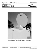
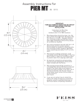
[AZIMUTH COLUMN READING WHEN EARTH STATION IS WEST OF SATELLITE]
[AZIMUTH COLUMN READING WHEN EARTH STATION IS EAST OF SATELLITE]
EARTH STATION ANTENNA LATITUDE (IN DEGREES NORTH OR SOUTH OF EQUATOR)
EARTH STATION ANTENNA AZIMUTH (IN DEGREES)
EARTH STATION ANTENNA AZIMUTH (IN DEGREES)
" L" IS THE DIFFERENCE BETWEEN THE EARTH STATION
ANTENNA SITE LONGITUDE AND THE SATELLITE LONGITUDE
AZIMUTH CHART
CHART 3
0
O
5
O
10
O
15
O
20
O
25
O
30
O
35
O
40
O
45
O
50
O
55
O
60
O
65
O
70
O
75
O
NORTHERN
HEMISPHERE
SOUTHERN
HEMISPHERE
WEST EASTWESTEAST
0
10
20
30
40
50
60
70
80
90
360
350
340
330
320
310
300
290
280
270
11

NOTE: All installations to conform to latest issue of
National Electrical Code.
Ground antenna mount assembly and feed cables in
accordance with current National Electrical Code and
local electrical codes. Figure 2.0 and 2.1 illustrates
typical grounding methods for the ground pole and
feed cables.
Clamps that provide a solid connection between ground
wire and ground source should be used.
Tighten and torque all hardware.
IMPOR
T
ANT
:
Sealing RF Coaxial Connector
:
The
copper-plated center conductor in the RF coaxial cable,
which connects receiv
er to LNB, can experience
electrolysis corrosion at the LNB connector
.
Moisture
and DC current causes this type of corrosion. To prevent
corrosion, apply a moderate coat of silicon grease to the
center conductor and wr
ap the entire connection with
CO
AX-SEAL
®
tape to seal.
ASSEMBLY AND INSTALLATION
1.2m System (Ref. Fig. 1.6)
Attach Side Feed Legs and Braces to left and right
sides of Reflector using M6 x 20mm Hex Bolts, Lock
W
ashers and Hex Nuts. (NOTE: Long formed end of
Feed Leg attaches to Reflector. Short formed end of
Brace attaches to inside of Reflector rim.) Attach flat-
ten end of Brace to Extension Plate, using M6 x
22mm Round Head, Square Neck Bolts, Tooth Lock
Washers, Flat Washers and Hex Nuts. Round Head
Square Bolt Fits on the top of Extension Plate. Tooth
Lock Washer fits between the flatten end of Brace
and Extension Plate, then Flat Washer and Hex Nut.
Attach Side Feed Legs to Support Block using M6 x
20mm Hex Nuts and Lock Washers. Leave all hard-
ware loose.
Tighten and torque hardware securing Braces, Side
Legs, and “U” Clip to Reflector and Support Block to 4 ft-
lbs (5.4 N-m). Tighten and torque M6 x 55mm “U” Bolt to
18-22 in-lbs (2-2.5 N-m).
TOOTH WASHER
BLOCK
"U" CLIP
BRACE
SIDE FEED
LEGS
(2 REQ)
RD HD SQ
NK BOLT &
ELASTIC LOCK
NUT
BOTTOM FEED
SUPPORT TUBE
HEX BOLT
LOCK WAHER
(2 REQ)
RD HD SQ
NK BOLT
FLAT WASHER
LOCK WASHER
HEX NUT
RD HD SQ NK BOLT
TOOTH WASHER
FLAT WASHER
HEX NUT
(2 REQ)
M6 x 20mm
HEX BOLTS
LOCK WASHERS
HEX NUTS
(2 REQ-BOTH SIDES)
HEX BOLT
FLAT WASHER
(2 REQ)
FIG. 1.6 - Installation of Feed/Feed Support Legs
to Antenna (1.2m Medium Duty)
NOTE: ALL INSTALLATION TO CONFORM
TO THE LATEST ISSUE OF THE
NATIONAL ELECTRIC CODE.
IMPORTANT
DRILL HOLE AND ATTACH
GROUND BEFORE POURING
CONCRETE INSIDE GROUND POLE.
GROUND POLE
GROUND LUG
25"-29"
APPROX.
GROUND WIRE
(TYPICAL #10 AWG COPPER, #8 ALUMINUM)
REFER TO NEC SECTION 810 AND LOCAL ELECTRIC
CODES FOR THE SPECIFIC AREA REQUIREMENTS.
APPLY SEALANT HERE, AFTER ASSEMBLY,
TO IMPROVE CORROSION RESISTANCE
DRILL HOLE THRU ONE WALL WITH
7/32" DIA. TWIST DRILL
1/4" EXTENSION TOOTH LOCK WASHER
1/4"-20 UNC x 5/8" HEX HEAD,
TYPE "D" POINT, SELF TAPPING SCREW
FIG. 2.0 - Typical Electrical Grounding for
Antenna Ground Pole
GROUNDING
*GROUND BLOCK
NEC SECTION 810-20
*GROUNDWIRE
NEC SECTION 810-20
*ITEMS NOT
INCLUDED
*COAXIAL CABLE
TO RECEIVER
*COAXIAL CABLE
FROM LNB
FIG. 2.1 - Grounding Feed Cables
7
90
80
70
60
50
40
30
20
10
0 10 20 30 40 50 60 70 80
0
EARTH STATION LATITUDE IN DEGREES NORTH OR SOUTH OF EQUATOR
ELEVATION IN DEGREES
" L" IS THE DIFFERENCE BETWEEN THE EARTH STATION
ANTENNA SITE LONGITUDE AND THE SATELLITE LONGITUDE
ELEVATION CHART
CHART 2
5
O
10
O
15
O
20
O
25
O
30
O
35
O
40
O
45
O
50
O
55
O
60
O
65
O
70
O
75
O
50
O
125
O
120
O
115
O
110
O
105
O
100
O
95
O
90
O
85
O
80
O
75
O
70
O
65
O
50
O
47.5
O
45
O
42.5
O
40
O
37.5
O
35
O
32.5
O
30
O
27.5
O
25
O
47.5
O
45
O
42.5
O
40
O
37.5
O
35
O
32.5
O
30
O
27.5
O
25
O
10

0 10 20 30 40 50 60 70 80
0
20
40
60
80
10
30
50
70
90
ANTENNA
FEED
NORTHERN SOUTHERN
POLARIZATION CHART SIGN VALUES (+ OR -) HEMISPHERE HEMISPHERE
ANTENNA SITE WEST OF SATELLITE LONGITUDE - +
ANTENNA SITE EAST OF SATELLITE LONGITUDE + -
EARTH STATION LATITUDE IN DEGREES NORTH OR SOUTH OF EQUATOR
POLARIZATION + OR — (SEE ILLUSTRATION)
" L" IS THE DIFFERENCE BETWEEN THE EARTH STATION
ANTENNA SITE LONGITUDE AND THE SATELLITE LONGITUDE
POLARIZATION CHART
+—
CHART 1
75
O
60
O
40
O
30
O
20
O
15
O
10
O
5
O
Feed Rotation (Facing Antenna)
For + Polarization, Rotate CCW (Counter Clockwise)
For - Polarization, Rotate CW (Clockwise)
9
8
Alignment with the satellite is obtained by setting polariza-
tion, elevation and azimuth. Charts 1, 2 & 3 are to determine
these values for your earth station antenna site. “∆L” is the
difference between the earth station antenna site longitude
and the satellite longitude. Use “∆L” and your earth station
latitude to obtain polarization, elevation or azimuth setting.
POLARIZATION OF THE FEED
Loosen Feed Horn Clamp Bolts and turn Feed clockwise or
counterclockwise, depending on being east or west of the
satellite as shown on Chart 1. For course setting, align
marks on the Horn Scale (Ref. Fig. 3.0). Polarization chart
assumes antenna system polarization is Tx vertical and
satellite vertical Pol is perpendicular to plane of geostation-
ary arc. For horizontal Tx of antenna, Feed must be rotated
90˚ from values shown. (Starting point for polarization
adjustment is 0˚, as shown in Figure 3.0.) Use a signal
strength measur
ing device for final polarization setting and
tighten horn clamp bolts to 4 ft-lbs (5.4 N-m).
ELEVATION
Use Chart 2 and determine your elevation setting. Loosen
Elevation Pivot Bolts and Bolts in curved slots (both sides)
of AZ/EL housing approximately 1 complete turn (Ref. Fig.
3.1). Turn Elevation Adjustment Bolt clockwise to decrease
elevation and counterclockwise to increase elevation. Align
the edge of the Clamp with appropriate mark on housing at
the desired elevation reading. This will be an approximate
setting. Optimum setting achieved when fine tuning.
NOTE: Degree values shown on Elevation Scale are Beam;
there is no need to compensate for any offset angle. (See
Appendix A, Outline Drawing).If clinometer is used, you must
compensate for offset angle.
AZIMUTH
Use Chart 3 and determine your azimuth setting. Values in
chart must be adjusted for magnetic deviation for your loca-
tion for correct compass reading. Rotate Reflector and
Mount pointing it to the correct compass reading. Slowly
sweep the antenna in azimuth until signal is found. If the
desired signal is not f
ound, increase or decrease ele
v
ation
setting and repeat the azimuth sweep (Ref. Fig. 3.2). Tighten
Half Clamp Bolts .
FINE TUNING
Use Signal Tuning Device for final adjustments to obtain
maxim
um antenna perf
or
mance
. Alternate between eleva-
tion and azimuth fine tuning to reach maximum signal
strength, until no improvement can be detected. Certain
models utiliz
e the optional azim
uth fine tune f
eature (ref
er to
Figure 3.2). This allows the azimuth to be fine tuned by loos-
ening the (4) Carriage Head Bolts and Swivel Nut which
allo
ws adjusting the Azim
uth Fine
T
une Adjusting Bolt f
or the
peak signal. When fine tuning is complete, tighten and
torque all AZ/EL hardw
are to 12 ft-lbs (16.3 N-m).
Do not
exceed 12 ft-lbs (16.3 N-m). Torque Clamp Hardware to 18
ft-lbs (24.4 N-m) in alternating sequence.
IMPORTANT: Recheck and repeat torque on four Clamp
Bolts, Fig. 3.1 in alternating sequence, until all Bolts are
equally torqued to 18 ft-lbs.
FIG. 3.0 - Polarization of the Feed
HORN SCALE
ALIGNMENT MARK
CLAMP BOLT
FIG. 3.1 - Setting the Elevation
EDGE OF CLAMP
BRACKET
EXAMPLE:
18" ELEVATION
ELEVATION ADJUSTING
SCREW
CURVED SLOT BOLT
ELEVATION
PIVOT
BOLT
CLAMP BOLT
(
4 PLCS)
FIG. 3.2 - Rotating Antenna for Azimuth
AZIMUTH FINE TUNE
ADJUSTING BOLT
HEX NUT,
CARRIAGE BOLT (4)
HEX NUT,
SWIVEL NUT
AZIMUTH
ANTENNA ALIGNMENT PROCEDURE
/