GSS HDC 480 CI AV Assembly Instructions Manual
- Type
- Assembly Instructions Manual

English
STC 160 Head-End Station
QPSK AV module
Notes on the Assembly Instructions.
As well as this supplementary Assembly
Instructions, the Assembly Instructions for the
STC
160
apply.
GSS
Grundig SAT Systems GmbH
Beuthener Strasse 43
D-90471 Nuremberg
Phone: +49 (0) 911 / 703 8877
Fax: +49 (0) 911 / 703 9210
Email: info@gss.de
Internet: www.gss.de
HDC 480 CI AV

- 2 - HDC 480 CI AV
Contents
1 Safety regulations .......................................................................................3
2 General information ....................................................................................3
2.1 Scope of delivery ..........................................................................3
2.2 Meaning of the symbols used ..........................................................4
2.3 Technical data ...............................................................................4
2.4 Description ...................................................................................5
3 Installation ..................................................................................................6
3.1 Retrofitting a CA module ................................................................6
3.2 Installing the digital module ............................................................7
3.3 Connecting the digital module .........................................................8
4 The control panel at a glance .......................................................................9
4.1 Menu items ...................................................................................9
4.2 Functions of the control panel buttons ...............................................9
5 Programming ............................................................................................10
5.1 Preparation .................................................................................10
5.2 Programming procedure ...............................................................10
5.3 Programming the digital module ....................................................12
Selecting the module / channel strip ..............................................12
LNB oscillator frequency; CA module .............................................13
Configuring the CA module, displaying card information ............13
Input symbol rate .........................................................................14
Input frequency ...........................................................................15
Station filter ................................................................................16
Audio stream for a TV channel ......................................................17
Volume level .............................................................................17
Identification of the stereo / dual tone ............................................18
Picture format signal, teletext mode ................................................18
Test lines .....................................................................................19
Subtitle functions..........................................................................19
Teletext subtitle page and standard ...........................................19
DVB subtitle page ...................................................................20
Black bar ...............................................................................21
Storing data ................................................................................21
6 Final procedures ........................................................................................22

- 3 - HDC 480 CI AV
1 safety regulations
• ThestandardsIEC/EN/DINEN50083resp.IEC/EN/DINEN60728must
be observed.
• Donotperforminstallationandserviceworkduringthunderstorms.
• Assembly, installation and servicing should be carried out by authorised
electricians.
• Switchofftheoperatingvoltageofthesystembeforebeginningwithassem-
bly or service work.
• Avoidshortcircuits!
• Observetherelevantstandards,regulationsandguidelinesontheinstalla-
tion and operation of antenna systems.
• Toensureelectromagneticcompatibility,makesureallconnectionsaretight
and the covers are screwed on securely.
• Noliabilityisacceptedfordamagecausedbyfaultyconnectionsorinap-
propriate handling of the device.
Check the head-end station according to the safety instructions listed in their
assembly instruction.
Takeprecautionstopreventstaticdischargewhenworkingonthedevice!
Electronic devices should never be disposed of in the household rubbish. In
accordance with directive 2002/96/EC of the European Parliament and the
European Council from January 27, 2003 which addresses old electronic and
electrical devices, such devices must be disposed of at a designated collection
facility. At the end of its service life, please take your device to one of these
public collection facilities for proper disposal.
2 general information
2.1 sCope of delivery
1 HDC 480 CI AV module
1 AV cable
1 Brief Assembly Instructions

- 4 - HDC 480 CI AV
2.2 meaning of the symbols used
Important note
—> General note
–
/
–
/
Optionaluseofthebuttons
• Performingworks
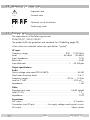
2.3 teChniCal data
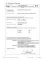
The requirements of the following are met:
2006/95/EC, 2004/108/EC
The product fulfils the guidelines and standards for CE labelling (page 23).
Unless otherwise noted all values are specified as "typical".
HF input:
Frequency range: ....................................................... 950 … 2150 MHz
Level: ..................................................................... 60 dBμV … 80 dBμV
Input impedance: ............................................................................75 Ω
Return loss: .....................................................................................8 dB
Input data rate: ...............................................................1 … 45 MSymb
Output specifications:
Audio
Noise voltage ratio rated (DIN 45633): ...........................................60 dB
Non-linear distortion factor: ............................................................0.6 %
Frequency range: ..........................................................20 Hz … 15 kHz
Level at -12 dB: .......................................................................500 mV
rms
Impedance: .....................................................................................1 kΩ
Video
Signal-to-noise ratio:.............................................................54 dB (rated)
Level (75 Ω): ..................................................................................1 V
pp
Impedance: ....................................................................................75 Ω
Connections:
SAT inputs: ............................................................................ 4 F-sockets
Connection strip (20-pin): ...................
For supply voltages and control circuits
AV output: ...........................................................................
26-pin
socket

- 5 - HDC 480 CI AV
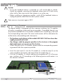
2.4 desCription
The module HDC 480 CI AV, in the following called digital module, has a QPSK
AV converter which simultaneously converts four QPSK modulated channels into
AV signals. It is equipped with four common interfaces, which enable the de-
scrambling of four scrambled channels when used in conjunction with four CA
modulesandfourappropriatesmartcards.Onechannelcanbedescrambled
with every common interface.
The
digital
module
has four SAT inputs and one AV interface, through which
the decoded AV signals are fed to the corresponding modulator module. Com-
ponents (e.g. LNB) which are connected upstream can be powered through
the SAT inputs.
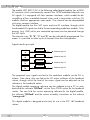
The channel strips "A" "B", "C" and "D" can be individually programmed. This
means it is possible to select up to 4 channels from four transponders.
Signal transfer principle:
Channel strip "A"
Channel strip "B"
Channel strip "C"
Channel strip "D"
TUNER
"A"
TUNER
"B"
TUNER
"C"
TUNER
"D"
CA module
CA module
CA module
CA module
The prepared input signals are fed to the modulator module via the AV in-
terface. From there, they are fed to the HF output collector of the head-end
station, through which the level of the output signal can be adjusted via the
software in the head-end station.
The
digital module
operating software can be updated using a PC or note-
book and the software "BE-Flash" via the 9-pin D-SUB socket on the head-end
station. You can find the current operating software for the
digital module,
the software "BE-Flash"
and the current assembly instructions
on the website
"www.gss.de".
This digital module is designed exclusively for use in the STC 160 head-end
station.

- 6 - HDC 480 CI AV
3 installation
Caution
– Ensure the head-end station is mounted so it will not be able to vibrate.
Avoid, for example, mounting the head-end station onto a lift shaft or any
other wall or floor construction that vibrates in a similar way.
– Before installing or changing a module, switch off the head-end station or
unplug the power cable from the mains power socket.
TakemeasurestoprotectagainstESD!
3.1 retrofit ting a Ca module
The digital module is equipped with four common interfaces for CA modules
of various scrambling systems and service providers. Scrambled channels can
only be descrambled with a CA module suitable for the scrambling system and
the corresponding smart card. The smart card contains all the information for
authorisation, descrambling and subscription.
– The hardware and software of the module HDC 480 CI AV have been thor-
oughly prepared and tested.
– Any changes made by program providers to the structures in the program
data might impair or even prevent this function.
– When working with a CA module, please read the corresponding operat-
ing manual from the respective provider.
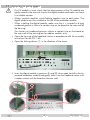
• Insertthesmartcard
1 into the CA module
2 so that the chip
3
on the
smart card faces the thicker side (top) of the CA module (fig. 1).
• PushtheCAmodule2 without canting into the guide rails 4 of the com-
mon interface slot 5 according to the following picture and contact it to
the common interface.
5
2
3
4
1

- 7 - HDC 480 CI AV
3.2 installing the digital module
– If a CA module is used, check that the plug contacts of the CA module are
tightly seated in the terminal strip on the digital module and make sure there
is a reliable contact.
– Always position modules which belong together next to each other. The
digital module must be installed to the left of the modulator module.
– When installing the digital module, make sure that it is inserted in a long
numbered groove in front of a contact strip on the board at the rear wall of
the housing.
The shorter not numbered grooves without a contact strip on the board at
the rear wall of the housing are for add-on modules only.
•
Openthehousingofthehead-end station in accordance with the assembly
instructions for the STC 160.
• Openthelockingdevice1 in the direction of the arrow.
1
• InsertthedigitalmoduleingroovesA and B of an open slot left to the as-
sociated modulator module
and gently slide it into the head-end station until
it makes contact with the board on the rear wall.
B
A
C

- 8 - HDC 480 CI AV
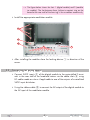
—> The figure below shows the slots 1 (digital module) and 2 (modula-
tor module). The slot between them (without a contact strip on the
board at the rear wall of the housing) is for an add-on module only.
• Installtheappropriatemodulatormodule.
1
D
G
E
F
• Afterinstallingthemodulesclosethelockingdevice1 in direction of the
arrow.
3.3 ConneCting the digital module
• ConnectSAT-IFinputsC of the digital module to the preinstalled Ftermi-
nals in the rear wall of the head-end station via the cable inlets E using
HF cables made on-site or if applicable to one of the outputs of a retrofitted
SAT-IF input distributor.
• UsingtheribboncableD to connect the AV output of the digital module to
the AV input of the modulator module.

- 9 - HDC 480 CI AV
4 the Control panel at a glanCe
4.1 menu items
Programme the module using the buttons on the head-end station control unit.
The menus appear on the two-line display of the control unit.
The parameters and functions to be set are underlined.
With the button select the channel strip / other modules.
You can use the button to select the following menu items:
– LNB oscillator frequency
– Symbol rate
– Input frequency
– Station filter
– Audio stream selection
– Audio output level
– Stereo decoding / audio type selection
– Picture format signal (WSS)
– Test lines
– Teletext subtitle / DVB subtitle / black shield
– Store
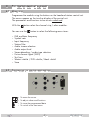
4.2 funCtions of the Control panel buttons
S
M
– To move the cursor
– To adjust values and functions
– To store the programmed data
– To switch to the next menu

- 10 - HDC 480 CI AV
5 programming
5.1 prepar ation
• Connectthedigitalmoduletoaprogrammedmodulatormodule.
—> For the programming of the output channels please read the assem-
bly instructions of the corresponding modulator module.
• ConnectthetestreceivertotheHFoutputonthemodulatormodule.
• Adjustthetestreceivertotheoutputchannelofthechannelstriptobeset:
Digital module – channel strip "A" —> modulator module – channel strip "A",
Digital module – channel strip "B" —> modulator module – channel strip "B",
Digital module – channel strip "C" —> modulator module – channel strip "C",
Digital module – channel strip "D" —> modulator module – channel strip "D".
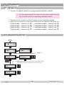
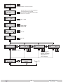
5.2 programming proCedure
Bx 1A
10600 MHz
LNB
>
A
Bx 1A
C5-12,S3-24
TWIN-SAT
C07
Böx 4
C5-12,S3-24
TWIN-SAT
C07
Bx 1B
WDR Köln
QUAD
V 12
SETUP
Bx 1A
Das Erste
QUAD
V 12
V 8
Bx 1A MENU
Information *)
1/6
M
M
/
/
/
/
M
Ein/On
Bx 1A
11836 MHz
FREQ
+0.2
/
/
Bx 1A
Das Erste
01/07 + TV
M
M
Bx 1A
Level
AUDIO
0 dB
M
Bx 1A
mpeg
AUDIO
DUAL norm
M
M
Bx 1A
01 / 02 “deu”
AUDIO
-26 … 6 dB
Bx 1A
WSS off
VIDEO
TXT on
M
/
/
/
/
Bx 1A
27500
SYMBOL
/
/
M
Das Menü wird nur bei Auswahlmöglichkeit
mehrerer Begleittöne angezeigt.
This menu is only displayed if several audio
streams are selectable.
*) Die angezeigte Information ist abhängig vom verwendeten CA-Modul
The information displayed is dependent on the CA module used
norm / swap
on / off
mpeg / VPS
/
/
/
/
M
Bx 1A
off
TESTLINES
on / off
Programmauswahl / Channel selection
Bx 1A
txt
SUBTITLE
150 west
Bx 1A
off
SUBTITLE
M
/
/
/
/
/
A
CANCEL
Bx 1A
S => STORE
MEMORY
S
M
M M
Bx 1A
dvb
M
west / east 0…63
off / txt / dvb / black
nur wenn Untertitel
verfügbar sind:
Sprache auswählen
only if subtitles are
available:
select language
SUBTITLE
– –
/
/
Bx 1A
black
SUBTITLE
40/10
BE160
Page 11

- 11 - HDC 480 CI AV
Bx 1A
10600 MHz
LNB
>
A
Bx 1A
C5-12,S3-24
TWIN-SAT
C07
Böx 4
C5-12,S3-24
TWIN-SAT
C07
Bx 1B
WDR Köln
QUAD
V 12
SETUP
Bx 1A
Das Erste
QUAD
V 12
V 8
Bx 1A MENU
Information *)
1/6
M
M
/
/
/
/
M
Ein/On
Bx 1A
11836 MHz
FREQ
+0.2
/
/
Bx 1A
Das Erste
01/07 + TV
M
M
Bx 1A
Level
AUDIO
0 dB
M
Bx 1A
mpeg
AUDIO
DUAL norm
M
M
Bx 1A
01 / 02 “deu”
AUDIO
-26 … 6 dB
Bx 1A
WSS off
VIDEO
TXT on
M
/
/
/
/
Bx 1A
27500
SYMBOL
/
/
M
Das Menü wird nur bei Auswahlmöglichkeit
mehrerer Begleittöne angezeigt.
This menu is only displayed if several audio
streams are selectable.
*) Die angezeigte Information ist abhängig vom verwendeten CA-Modul
The information displayed is dependent on the CA module used
norm / swap
on / off
mpeg / VPS
/
/
/
/
M
Bx 1A
off
TESTLINES
on / off
Programmauswahl / Channel selection
Bx 1A
txt
SUBTITLE
150 west
Bx 1A
off
SUBTITLE
M
/
/
/
/
/
A
CANCEL
Bx 1A
S => STORE
MEMORY
S
M
M M
Bx 1A
dvb
M
west / east 0…63
off / txt / dvb / black
nur wenn Untertitel
verfügbar sind:
Sprache auswählen
only if subtitles are
available:
select language
SUBTITLE
– –
/
/
Bx 1A
black
SUBTITLE
40/10
Page 10

- 12 - HDC 480 CI AV
5.3 programming the digital module
Notes:
– Entries are saved by pressing the button.
—> You will be returned to "Selecting the module/channel strip".
– The programming process can be cancelled by pressing and holding the
button.
—> You will be returned to "Selecting the module/channel strip".
• Switchonthehead-end station.
SETUP
V 8
Ein/On
BE160
—>
The display shows
"SETUP BE160"
and the software
version of the
head-end station (e.g. V 8).
—> The output level of the output collector can be adjusted in the
"SETUP" menu (see STC 160 assembly instructions).
seleCting the module / Channel strip
• Press repeatedly if necessary to select the particular module (Bx ...)
or channel strip
"A", "B", "C" or "D"
to be programmed.
Bx 1A
C5-12,S3-24
TWIN-SAT
C07
Böx 4
C5-12,S3-24
TWIN-SAT
C07
Bx 1B
WDR Köln
QUAD
V 12
Bx 1A
Das Erste
QUAD
V 12
—> The display shows, e.g., the "Bx 1A QUAD" menu.
"Bx" indicates the slot
"1" indicates slot no. 1
"A" indicates channel strip "A"
"Das Erste" name of the selected channel
"V 12" software version of the module

- 13 - HDC 480 CI AV
—> The following programming procedure shows the programming of
channel strip "A".
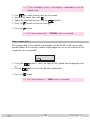
• Pressthe button:
—> The "LNB oscillator frequency" – "LNB" menu is activated.
lnb osCill ator frequenCy; Ca module
In this menu you have to set the LNB oscillator frequency. If a CA module is
used, herein the submenu for its setting can be selected.
Bx 1A
10600 MHz
LNB
>
Bx 1A MENU
Information *)
1/6
• Usingthe
buttons, select the digit of the oscillator frequency to be
set.
• Use the
buttons to set the oscillator frequency of the LNB being
used
.
Skip the setting of the CA module:
• Pressthe button.
—> The "Input symbol rate" – "SYMBOL" menu is activated (page 14).
Einstellung des CA-Moduls durchführen:
• Pressthe button.
—> The "CA module" – "MENU" submenu is activated.
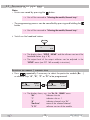
Configuring the Ca module, displaying Card information
A menu has been provided for these settings, which is displayed on your TV
screen. The menu varies according to which CA module is used. For this rea-
son, please refer to the operating manual of your particular CA module. The
relevant information is shown on the display of the head-end station.
Bx 1A MENU
Information *)
1/6

- 14 - HDC 480 CI AV
—> *) The information shown in the display is dependent on the CA
module used.
• Use to select a menu item on the screen.
• Activatethemenuitemwith .
• Selecttherequiredfunctionwiththe buttons.
• Pressthe button to store the settings.
• Pressthe button.
—> The "Input symbol rate" – "SYMBOL" menu is activated.
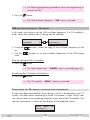
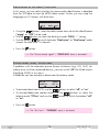
input symbol rate
The symbol rate of the satellite transponder can be found in the current trans-
ponder tables of the various satellite
trade magazines or on the website of the
respective service
provider.
Bx 1A
27500
SYMBOL
•
Using the
buttons, select the digit of the symbol rate displayed to be
set.
• Usethe
buttons to set the desired symbol rate.
• Pressthe button.
—> The "Input frequency" – "FREQ" menu is activated.

- 15 - HDC 480 CI AV
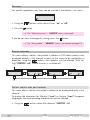
input frequenCy
Bx 1A
11836 MHz
FREQ
+0.2
—> Once the HF receiver has synchronised to the input signal, any
offset to the target frequency is displayed in MHz, e.g. "* 0.2".
—> If a question mark "?" appears in the second line of the display,
there is no input signal present. Check the configuration of the an-
tenna system and head-end station as well as the preceding settings
of the module in question.
•
Using the
buttons, select the digit
of the frequency displayed
to be set.
• Usethe
buttons to set the input frequency.
•
Press the buttons to adjust the input frequency displayed so that the
frequency offset amounts to less than 1MHz.
—>
A status LED indicates the quality of the received input signal:
LED indicator Signal quality
Green Good
Orange Poor
Red no signal
• Pressthe button.
—> The "Station filter" menu is activated.

- 16 - HDC 480 CI AV
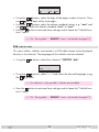
station filter
In this menu, select the channel from the data stream that is to be made avail-
able through this channel strip.
If the error message "SERVICE no transponder" appears, no input signal
is present. In this case, you should check the previous settings as well as the
configuration of the SAT antenna system.
If the "scanning ..." message appears on the display, the table of received
channels is being read. Please wait until this process is finished.
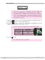
As soon as the station filter has found all of the TV or radio channels, the corre-
sponding data appears in the display of the head-end station.
Bx 1A
Das Erste
01/07 + TV
Meaning of the indicators shown in this example:
"01/07" The first of a total of 7 channels has been activated.
" + " The audio stream for the current TV channel is avail-
able in several languages.
"TV" The data on the display corresponds to a TV channel.
"Das Erste" Channel name
Other possible indicators:
"RA" The data on the display corresponds to a radio chan-
nel.
" * " A star indicates that this TV or radio channel is scram-
bled. To enable the channels, a CA module and a
s
mart card from the respective service provider
are
required.
—> For radio channels, the background of the screen of the connected
TV or test receiver is darkened.
—> If a service number (e.g. "SERVICE 131") appears instead of "TV" or
"RA", this indicates that an unnamed station or an undefined data
stream is being received.
• SelectthedesiredTVorradio
channel
with the buttons.
• Pressthe button.

- 17 - HDC 480 CI AV
—> If the selected channel is broadcasted with two or more audio
streams, the "Audio stream for a TV channel" – "AUDIO" menu will
appear.
Otherwise the "Volume level" –
"AUDIO Level" menu is activated
(see page 17).
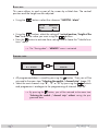
audio stream for a tv Channel
This menu only appears if the selected channel is broadcasted with two or
more audio streams (languages). In this menu, select the desired audio stream
from the transport stream.
Bx 1A
01 / 02 “deu”
AUDIO
• Usethe buttons to select the audio stream you want.
• Pressthe button.
—> The "Volume level" – "AUDIO Level" menu is activated.
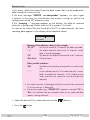
volume level
In this menu, you can balance unequal volume levels of TV and radio stations
in the various channel strips.
Bx 1A
Level
AUDIO
0 dB
• Setthevolumeleveltothesamelevelasthelevelsoftheotheroutputchan-
nels using the
buttons (+6dB … -26dB), if necessary.
• Pressthe button.
—> The "Identification of the stereo / dual tone" – "AUDIO" menu is
activated.

- 18 - HDC 480 CI AV
identifiCation of the stereo / dual tone
In this menu, you can select whether the stereo audio identification is decoded
from the VPS data or from the MPEG data stream. Further you can swap the
languages on TV stations with dual tone.
Bx 1A
mpeg
AUDIO
DUAL norm
• Usingthe
buttons, select the data stream from which the identification
("mpeg" or "VPS") to be used.
•
Use the buttons to select the dual tone code "DUAL …" setting.
• Usethebuttons
to switch between "Dual norm" or "Dual swap" audio
streams for dual tone TV channels.
• Pressthe button.
—> The "Picture format signal" – "VIDEO WSS" menu is activated.
piCture format signal, teletext mode
If problems with the automatic picture format switchover (e.g. 4:3, 16:9, Let-
terbox) arise with the connected devices, you can switch "off" the Wide Screen
Signalling (WSS) in this menu.
In addition you can
activate or deactivate the teletext mode.
Bx 1A
WSS off
VIDEO
TXT on
•
To activate/deactivate WSS, use the
buttons to select "off" or "on".
• Toactivate/deactivate teletext mode,
use the
buttons to select the
teletext mode "
TXT on
" and use the
buttons to switch the teletext "off"
or "on".
• Pressthe button.
—> The "Test lines" – "TESTLINES" menu is activated.

- 19 - HDC 480 CI AV
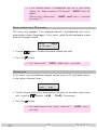
test lines
For specific applications test lines can be inserted in the teletext in this menu.
Bx 1A
off
TESTLINES
• Usingthe
buttons switch the test lines "on" or "off"
• Pressthe button.
—> The "Subtitle functions" – "SUBTITLE" menu is activated.
If you do not want to change this setting, press the
button.
—> The "Storing data" – "MEMORY" menu is activated (see page 21).
subtitle funCtions
This menu allows subtitles (transmitted in teletext or DVB data stream) to be
displayed directly in the channel or parts of the screen to be masked by a
black bar.
U
sing the
buttons, the submenus can be selected. With set-
ting "SUBTITLE - off" subtitle function is switched off.
Bx 1A
txt
SUBTITLE
150 west
Bx 1A
off
SUBTITLE
M M M
Bx 1A
dvb
M
SUBTITLE
– –
Bx 1A
black
SUBTITLE
40/10
teletext subtitle page and standard
This menu allows subtitles transmitted in teletext to be displayed directly in the
channel.
To display the characters for Western ("west") or Eastern ("east") European
languages, the corresponding character set can be selected.
•
U
sing the
buttons select the submenu "SUBTITLE - txt".

- 20 - HDC 480 CI AV
Bx 1A
txt
SUBTITLE
150 west
• U
sing the
buttons select the digit of the page number to be set. Then
use
to set each of the three digits.
• U
sing the
buttons select the
teletext standard setting, e.g. "west" and
use to select the teletext standard "west" or "east".
• Press
the
button to activate these settings and to leave the
"Subtitle func-
tions" menu
.
—> The "Storing data" – "MEMORY" menu is activated (see page 21).
dvb subtitle page
This menu allows subtitles transmitted in a DVB data stream to be displayed
directly in the channel.
The language of the subtitles can be selected.
•
U
sing the
buttons select the submenu "SUBTITLE - dvb".
Bx 1A
dvb
SUBTITLE
– –
• U
sing the
buttons select
"– –"
and select the desired language using
the buttons
.
—> This selection is only possible if subtitles are available.
• Press
the
button to activate these settings and to leave the
"Subtitle func-
tions" menu
.
—> The "Storing data" – "MEMORY" menu is activated (see page 21).
Page is loading ...
Page is loading ...
Page is loading ...
-
 1
1
-
 2
2
-
 3
3
-
 4
4
-
 5
5
-
 6
6
-
 7
7
-
 8
8
-
 9
9
-
 10
10
-
 11
11
-
 12
12
-
 13
13
-
 14
14
-
 15
15
-
 16
16
-
 17
17
-
 18
18
-
 19
19
-
 20
20
-
 21
21
-
 22
22
-
 23
23


GSS HDC 480 CI AV Assembly Instructions Manual
- Type
- Assembly Instructions Manual
Ask a question and I''ll find the answer in the document
Finding information in a document is now easier with AI
Related papers
-
GSS HDC 460 CI AV Assembly Instructions Manual
-
-
-
-
-
-
-
-
-
Other documents
-
Triax CGS 470 Assembly Instruction Manual
-
Grundig Refrigerator HDM 2370 P CI User manual
-
König KN-LNB-QD10 Datasheet
-
-
-
-
-
-
 TANDBERG TT-1222 Reference guide
-
