Page is loading ...

Assembly Instruction
PHIS 1000 S

- 2 - PHIS 1000 S
Contents
1 Safety regulations and notes ........................................................................4
2 General information ....................................................................................5
2.1 Packing contents ............................................................................5
2.2 Meaning of the symbols used ..........................................................5
2.3 Technical data ...............................................................................5
2.4 Description ...................................................................................6
2.5 Software query..............................................................................7
3 Assembly ....................................................................................................8
3.1 Installing the cassette......................................................................8
3.2 EMC regulations ............................................................................9
3.3 Cassette overview........................................................................10
3.4 Connecting the cassette ................................................................10
3.5 Retrofitting a CA module ..............................................................11
4 The control panel at a glance .....................................................................12
4.1 Menu items .................................................................................12
4.2 Control panel ..............................................................................12
5 Programming ............................................................................................13
5.1 Overview ...................................................................................13
Function "Virtual Station Tables" ....................................................13
Programming via station tables.................................................13
5.2
Programming procedure ...................................................................14
5.3 Creating station tables .................................................................17
The structure of the text file for programming station tables ...............18
5.4 Uploading the station tables to the cassettes ....................................22
5.5 Programming the cassette .............................................................23
Selecting the cassette ...................................................................23
Selecting the station table .............................................................24
Setting the Ethernet parameters .....................................................24
Setting the hardware IP address of the cassette ...............................25
Setting the address range .............................................................26
Setting the address of the gateway ................................................26
Setting the UDP port ...................................................................... 27
Selecting the input data stream ......................................................27
LNB oscillator frequency / control voltage ......................................28
LNB oscillator frequency ..........................................................28
DiSEqC commands .................................................................28
Setting the input symbol rate .........................................................29

- 3 - PHIS 1000 S
Setting the DVB mode ..................................................................30
Setting the input frequency ............................................................30
Setting the output parameters ........................................................32
Setting the IP addresses for the outputs ...........................................33
Switching the IP address off or on ..................................................34
Selecting the transmission protocol .................................................34
Setting the port number ................................................................34
Defining the quantity of data packets .............................................35
Setting the forward error correction ...............................................35
Setting the transmission channel ....................................................35
Setting the output data rate ...........................................................36
Allocating services manually .........................................................37
Selecting the sound options of the service .......................................38
Automatic/Manual PIDs ...............................................................38
Switching DVB service information on or off....................................39
Stuffing the output data rate ..........................................................40
Displaying the output data rate......................................................40
Factory reset ...............................................................................41
Saving settings ............................................................................41
Operation with a CA module ........................................................42
Setting the PID monitoring ........................................................42
Configuring the CA module .....................................................42
Descrambling services .............................................................44
6 Final procedures ........................................................................................45

- 4 - PHIS 1000 S
1 safety regulations and notes
• Assembly, installation and servicing should be carried out by authorised
electricians.
• Switch off the operating voltage of the system before beginning with assem-
bly or service work or pull out the mains plug.
• Do not perform installation and service work during thunderstorms.
• Install the system so it will not be able to vibrate…
- in a dust-free, dry environment
- in such a manner that it is protected from moisture, fumes, splashing wa-
ter and dampness
- somewhere protected from direct sunlight
- not within the immediate vicinity of heat sources
- in an ambient temperature of 0 °C to +50 °C. In case of the formation of
condensation wait until the system is completely dried.
• Ensure that the head-end station is adequately ventilated. Do not cover the
ventilation slots.
• Beware of short circuits
• No liability is accepted for any damage caused by faulty connections or
inappropriate handling.
• Observe the relevant standards, regulations and guidelines on the installa-
tion and operation of antenna systems.
• The standards EN/DIN EN 50083 and IEC/EN/DIN EN 60728 must be
observed.
• For further information please read the assembly instructions for the head-
end station used.
• Test the software versions of the head-end station and the cassette and
update them if necessary. The current software versions can be found at
"www.mygss.eu".
Take action to prevent static discharge when working on the device!
Electronic devices should never be disposed of in the household rubbish. In
accordance with directive 2002/96/EC of the European Parliament and the
European Council from January 27, 2003 which addresses old electronic and
electrical devices, such devices must be disposed of at a designated collection
facility. At the end of its service life, please take your device to one of these
public collection facilities for proper disposal.

- 5 - PHIS 1000 S
2 general information
2.1 PaCking Contents
1 Cassette PHIS 1000 S 2 RF cables
1 LAN cable 2 F jack-to-jack adapter
4 Lock washers 2 Thin nuts
1 Brief assembly instructions 1 Measuring log
2.2 meaning of the symbols used
Important note
—> General note
• Performing works
2.3 teChniCal data
The devices meet the following EU directives:
2011/65/EU, 2014/30/EU, 2014/35/EU
The product fulfils the guidelines and standards for CE labelling (page 46).
Unless otherwise noted all values are specified as "typical".
RF input
Frequency range: ....................................................... 925 … 2150 MHz
Level range: ............................................................ 60 dBμV … 80 dBμV
Return loss: ..................................................................................> 8 dB
DVB-S modes: ............................................ QPSK
1
/
2
,
2
/
3
,
3
/
4
,
5
/
6
,
7
/
8
DVB-S2 modes: ...................QPSK
1
/
2
,
3
/
5
,
2
/
3
,
3
/
4
,
4
/
5
,
5
/
6
,
8
/
9
,
9
/
10
8PSK
3
/
5
,
2
/
3
,
3
/
4
,
5
/
6
,
8
/
9
,
9
/
10
Symbol rate DVB-S: .......................................... QPSK: 2 … 45 MSymb/s
Symbol rate DVB-S2: ........................................ QPSK: 10 … 30 MSymb/s
8PSK: 10 … 31 MSymb/s
LNB control voltage (sound/DiSEqC
TM*
) ............................
max. 65 mA
(switchable)
LAN interface
Standard: .............................................................................100-BASE-T
Data rate: ............................................................................... ≤ 80 MBit
Protocols: .......................................................... UDP (User Data Protocol),
RTP (Real-Time Transport Protocol)

- 6 - PHIS 1000 S
Connections
SAT inputs: ............................................................................. 2 F sockets
RF output: ..........................................................1 IEC socket (no function)
LAN: ................................................................................ 1 RJ 45 socket
Connection strip (10-pin): ..................for supply voltages and control circuits
RS 232 socket: ..................................... serial interface for software update
Conditional access:...........................several channels can be descrambled.
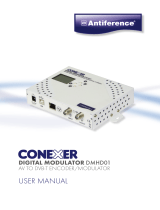
2.4 desCriPtion
The cassette is a
DVB-S2 / SPTS
converter which combines modulated services
(programmes) in accordance with the DVB-S-/DVB-S2 standard into one data
stream in the TPS module. From this up to 12 data streams, containing one
service each, are emitted at the LAN interface. For operating the cassette in a
LAN network it can be assigned its own IP address. The cassette is equipped
with two tuners. The accompanying channel strips consist of the digital SAT
tuners and the digital signal processing levels. From the resulting data streams
of the "
Tuner A
" and "
Tuner B
" channel strips up to 12 services can be taken
and assigned with each an IP address
.
Principle signal path:
TPS
"Tuner A"
"Tuner B"
CA-Modul
CA module
IP address:
Service 1 227.40.50.1
Service 2 227.40.50.2
Service 3 227.40.50.3
Service 4 227.40.50.4
Service 12 227.40.50.12
The channel strip "
Tuner A
" can descramble scrambled channels via a cor-
responding CA module.
Two LEDs provide an indication of the signal quality
with their colour. The transmission of the DVB service information EIT as well
as teletext (TXT), subtitle (SUB) and AC3 tone can be individually activated or
deactivated.
—>
EIT (Event Information Table):
For each service, event information is transmitted (such as starting
time, duration, scrambling etc.).

- 7 - PHIS 1000 S
A control voltage for a DiSEqC
TM
controlled multi switch which is not suitable
as power supply is present at the antenna input (use an external power sup-
ply).
The cassette is controlled with the head-end station control unit as well as with
station tables which can be uploaded and stored to the cassettes via Ethernet.
The LEDs for the LAN interface show whether a network connection exists and
whether a data transfer is in progress.
When the head-end station is switched on, the two-line LC display shows the
software version of the control unit.
To operate this cassette the software version of the control unit must be "V 45"
or higher. You can find the current operating software for the control unit and
the cassette, the software "BE-Flash" and the current assembly instructions on
the website "www.mygss.eu".
The cassette is intended for use in the
PROFI-LINE
head-end stations.
2.5 software query
Control unit
If necessary, you can activate the indication of the software version of the
control unit manually:
• Press any two keys on the control unit of the head-end station simultaneously
until the display goes dark and the software version, e.g. "V 45" appears.
Cassette
After activating the cassette the software version of the cassette is displayed
(see page 23).

- 8 - PHIS 1000 S
3 assembly
3.1 installing the Cassette
– Ensure the head-end station is mounted so it will not be able to vibrate.
Avoid, for example, mounting the head-end station onto a lift shaft or any
other wall or floor construction that vibrates in a similar way.
– Before installing or changing a cassette unplug the power cable from the
mains power socket.
• Remove the fastening screws 1 of an unoccupied slot from the bracket of
the head-end station.
• Insert the cassette in this slot and push it into the housing.
• Align the cassette and apply slight pressure to connect it to the connections
of the board and the RF bus bar.
• Fasten the cassette with the screws 1.
• If you need the DiSEqC
TM
control the input signal must not be fed via the
input distributor. Insert the cable termi nals together with the contact washers
in corresponding open ings (knock-outs). Therefore observe the EMC regula-
tions on page 9.
1
1

- 9 - PHIS 1000 S
3.2 emC regul ations
To comply with the current EMC regulations, it is necessary to connect the lines
leading in and out of the head-end station using cable terminals.
When mounting the cassette in a head-end station which is installed in a 19"
cabinet, make sure the connections leading in and out for the 19" cabinet are
made using cable terminals.
CLASS
KLASSE
The attenuation of shielding of the connection lines for ASI and antenna must
meet the requirements for "Class A".
• Insert the required number of cable terminals in the openings provided in
the head-end station or in the 19
"
cabinet.
Tighten the nuts on the cable terminals until the teeth on the lock washer have
penetrated the exterior coating and a good connection is made between the hous-
ing and cable terminals.

- 10 - PHIS 1000 S
3.3 Casset te overview
5
6
7
8
9
!
@
2
1
4
3
0
1 Status LED
of channel strip "
B
"
2 SAT IF input
of channel strip "
B
"
3 Status LED
of channel strip "
A
"
4 SAT IF input
of channel strip "
A
"
5 Status LED of the LAN interface (data transfer)
6
LAN socket
7 Status LED of the LAN interface (network connection)
8 not used
9 not used
0 Type label
! Slot for a CA module
@ D-SUB socket "RS 232"
The operating software of the cassette can be updated via the
9-pin D-SUB socket "RS 232" using a PC or notebook and the
software "BE-Flash".
You can find the current operating software on the website
"www.mygss.eu".
3.4 ConneCting the Cassette
• Connect the RF connections to the inputs
4
(channel strip "
Tuner A
") and
2
(channel strip "
Tuner B
"). To connect a DiSEqC
TM
controlled multi switch
2 Fjack-to-jack adapters (cable connectors) are attached.
—> If you need the DiSEqC
TM
control the input signal must not be fed via
the input distributor.
The control voltage for a DiSEqC
TM
controlled multi switch which is
present at the antenna input is not suitable as its power supply.
Therefore use an external power supply.
• Connect the LAN socket
6
.
—> In order to avoid restrictions of the network data rate (and therefore
possible disturbances) we recommend to operate other applications
like e.g. Internet, VOIP telephony etc. in separated networks.
—> Exclusively use "Layer 3 switches", which support the IGMP protocol.

- 11 - PHIS 1000 S
3.5 retrofit ting a Ca module
The cassette is equipped with a common interface. It allows you to connect a
CA module for various
scrambling
systems and service providers.
Scrambl
ed
channels can only be de
scramble
d with a CA module suitable for the
scram-
bl
ing system and the corresponding smart card. The smart card contains all
the information for authorisation, de
scrambl
ing and subscription.
–
Check with the distributor or manufacturer of the CA module to be used to
ensure that it is suitable for de
scrambl
ing several services.
– The hardware and software of this cassette have been thoroughly prepared
and tested. Any changes made by service providers to the data structures in
the service data might impair or even prevent this function.
– When working with the CA module, please read the corresponding operat-
ing manual from the respective provider.
• Insert the smart card 1 into the CA module 2 so that the chip 3 on the
smart card faces the thicker side (top) of the CA module.
• Insert the CA module into the guide rails of the CA slot 4 with the top side
of the CA module facing the top side of the cassette.
• Push the CA module without canting into the guide rails of the CA slot 4
and contact it to the common interface.
34 12

- 12 - PHIS 1000 S
4 the Control Panel at a glanCe
4.1 menu items
Programme the
cassette
using the buttons on the control unit of the head-end
station. The two-line display of the control unit then shows the menus.
The parameters and functions to be set are underlined.
Use the key to select the following main menu items:
– Programme tables (optionally*)
– Setting Ethernet parameters
– Selecting the Input (optionally*)
– Assignment of the IP addresses (optionally*)
– Data Mode
– Displaying the data rate
– Factory reset
*) depending on the activation of the
virtual station tables.
4.2 Control Panel
The key pad on the head-end station is used to scroll through the menus:
scrolls forward through the menus.
select parameters in the menus.
set values, initiate actions.
selects sub-menus.
scrolls backward through the menus.
saves all entries.
BE-Remote V 45
PROFESSIONAL

- 13 - PHIS 1000 S
5 Programming
5.1 overview
Points 5.2/5.5 describes the programming of the cassette via the operating unit
of the head-end station.
The programming of the stations to be received can also be done via a text file
(station tables) which is uploaded to the cassettes.
funCtion "virtual station tables"
For special applications it is possible at a combination of cassettes
PHIS 1000 S
("receiving cassettes") and PSPT/Q 1000 ("transmitting cassettes")
to change the
configuration quickly via "virtual station tables".
Here, the programming of several station tables (LOCATIONS) of the receiving
cassettes as well as their assignment to the transmission channels (transponders)
of the transmitting cassettes is done by a text file which must be uploaded to the
cassettes.
The switchover of the different station tables is done via the menu "LOCATION"
in the
PHIS 1000 S cassettes. This menu only appears if station tables were up-
loaded before. The menus "INPUT" and "IP-OUT" then are hidden.
In point 5.3 the structure of a corresponding text file and in point 5.4 the pro-
gramming of the cassettes (upload) is described.
Progr am ming via station tables
• First set the "hardware" IP addresses of all cassettes
PHIS 1000 S and
PSPT/Q 1000
.
• Create the text file (station tables) using a text editor.
• Upload the text file (station tables) to the corresponding cassettes.
• Finally programme the cassettes.

- 14 - PHIS 1000 S
5.2
Programming ProCedure
BE–Remote
please wait …
V 45
Box 4
V 5
HOT-SPTS
0.128 – – –
Box 1
………
……
……
Bx 1A
C5-12,S3-24
TWIN-SAT
C07
Böx 4
C5-12,S3-24
TWIN-SAT
C07
Box 5
………
……
……
+
t > 10 s
Bx 4
stat =>
ETHERNET
Options
stat / DHCP
Bx 4
---
LOCATION
A
A
Bx 4
192.168. 0. 1
IP-GATEWAY
Bx 4
255.255.255. 0
IP-MASK
▶
◀
/
Bx 4
192.168. 0.128
IP-ADDR
▶
◀
/
▶
◀
/
Bx 4
60000
UDP-PORT
▶
◀
/
B
▶
0 … 65535
Ein / On
Bx 4
0 Mbps
DATARATE
Bx 4
constant
DATAMODE
M
B
A
▶
Bx 4
Defaults
FACTORY
=>
Bx 4
STORE
FACTORY
=> M
M
Bx 4
DELETE
LOCATION
=> M
Programmtabellen
Channel tables
nur bei Funktion "virtuelle Programmtabellen"
only with function "Virtual station tables"
nicht bei Funktion "virtuelle Programmtabellen"
not with function "Virtual station tables"
Tuner A /
Tuner B
Bx 4A
11836 -1.8
FREQ
CN 12
Bx 4A
27500 DVB-S
SYMBOL
▶
◀
/
▶
◀
/
Bx 4A
10600 MHz
LNB
off
▶
Bx 4
Tuner A OK
INPUT
=>
Kanalzug “A” mit CA-Modul
Channel strip “A“ with CA module
Nur wenn "PIDS" –> "manual"
Only if "PIDS" –> "manual"
*DiSEqC
TM
is a trademark of EUTELSAT
Kanalzug “A” ohne CA-Modul,
Kanalzug “B” /
Channel strip “A“
without CA module,
Channel strip “B“
DVB-S / QPSK… /
8PSK… / DTV…
▶
◀
/
DiSEqC
TM*
:
off/– –Hh …DFV1
10600 / 9750
27500 / 22000
IP-OUT 1
…
IP-OUT 12
IP 1
227. 40. 50. 1
OUT-IP
IP 1
7 off
PKTS / FEC
IP 1
off UDP
MODE / PORT
1234
▶
Bx 4
Das Erste
IP-OUT 1
=>
on / off
UDP / RTP,
0 … 65535
copy
off / 10/9 … 20/19
Annex A / Annex B
001/016IP 1 TV
Das Erste
Bx 4
ac3 txt sub eit
OPTIONS
AC3 / ac3, TXT / txt,
SUB / sub, EIT / eit
(ON / off)
all / 01/…
IP 1
all
AUDIO
copy1 … 7
copy
auto
constant /
unmodified
Bx 4A
Menu <=
CA
=> Edit
*) Die angezeigte Information ist
abhängig vom verwendeten
CA-Modul.
The information displayed is
dependent on the CA module
used.
Bx 4A 01/03
Information *)
MENU
Bx 4A TV X
. . . .
04/09
X – entschlüsseln
descrambling
0 – nicht entschlüsseln
no descrambling
X / 0
nächster Service
next service
Bx 4A
PID Check
CA
on
▶
◀
on / off
M
▶
◀
/
▶
◀
/
▶
◀
/
▶
◀
/
IP 1
( 7.3) >
DATARATE
! 10.0 MB
auto
2 … 80.0 MBits
▶
◀
/
manual/auto
manual
auto
IP 1
manual
PIDS
▶
◀
/
Bedienhinweise
"blättert" Menüs vorwärts.
"blättert" Menüs rückwärts.
wählen die Eingabeposition
wählt Untermenü
stellen Werte ein,.
speichert alle Eingaben.
1 zeigt die Eingabeposition
Operating Hints
scrolls forward through the menu.
scrolls backward through the menu.
select the enter position.
selects a submenu.
set values and triggers actions.
saves all entries.
1 shows the enter position
Page 16

- 15 - PHIS 1000 S
BE–Remote
please wait …
V 45
Box 4
V 5
HOT-SPTS
0.128 – – –
Box 1
………
……
……
Bx 1A
C5-12,S3-24
TWIN-SAT
C07
Böx 4
C5-12,S3-24
TWIN-SAT
C07
Box 5
………
……
……
+
t > 10 s
Bx 4
stat =>
ETHERNET
Options
stat / DHCP
Bx 4
---
LOCATION
A
A
Bx 4
192.168. 0. 1
IP-GATEWAY
Bx 4
255.255.255. 0
IP-MASK
▶
◀
/
Bx 4
192.168. 0.128
IP-ADDR
▶
◀
/
▶
◀
/
Bx 4
60000
UDP-PORT
▶
◀
/
B
▶
0 … 65535
Ein / On
Bx 4
0 Mbps
DATARATE
Bx 4
constant
DATAMODE
M
B
A
▶
Bx 4
Defaults
FACTORY
=>
Bx 4
STORE
FACTORY
=> M
M
Bx 4
DELETE
LOCATION
=> M
Programmtabellen
Channel tables
nur bei Funktion "virtuelle Programmtabellen"
only with function "Virtual station tables"
nicht bei Funktion "virtuelle Programmtabellen"
not with function "Virtual station tables"
Tuner A /
Tuner B
Bx 4A
11836 -1.8
FREQ
CN 12
Bx 4A
27500 DVB-S
SYMBOL
▶
◀
/
▶
◀
/
Bx 4A
10600 MHz
LNB
off
▶
Bx 4
Tuner A OK
INPUT
=>
Kanalzug “A” mit CA-Modul
Channel strip “A“ with CA module
Nur wenn "PIDS" –> "manual"
Only if "PIDS" –> "manual"
*DiSEqC
TM
is a trademark of EUTELSAT
Kanalzug “A” ohne CA-Modul,
Kanalzug “B” /
Channel strip “A“
without CA module,
Channel strip “B“
DVB-S / QPSK… /
8PSK… / DTV…
▶
◀
/
DiSEqC
TM*
:
off/– –Hh …DFV1
10600 / 9750
27500 / 22000
IP-OUT 1
…
IP-OUT 12
IP 1
227. 40. 50. 1
OUT-IP
IP 1
7 off
PKTS / FEC
IP 1
off UDP
MODE / PORT
1234
▶
Bx 4
Das Erste
IP-OUT 1
=>
on / off
UDP / RTP,
0 … 65535
copy
off / 10/9 … 20/19
Annex A / Annex B
001/016IP 1 TV
Das Erste
Bx 4
ac3 txt sub eit
OPTIONS
AC3 / ac3, TXT / txt,
SUB / sub, EIT / eit
(ON / off)
all / 01/…
IP 1
all
AUDIO
copy1 … 7
copy
auto
constant /
unmodified
Bx 4A
Menu <=
CA
=> Edit
*) Die angezeigte Information ist
abhängig vom verwendeten
CA-Modul.
The information displayed is
dependent on the CA module
used.
Bx 4A 01/03
Information *)
MENU
Bx 4A TV X
. . . .
04/09
X – entschlüsseln
descrambling
0 – nicht entschlüsseln
no descrambling
X / 0
nächster Service
next service
Bx 4A
PID Check
CA
on
▶
◀
on / off
M
▶
◀
/
▶
◀
/
▶
◀
/
▶
◀
/
IP 1
( 7.3) >
DATARATE
! 10.0 MB
auto
2 … 80.0 MBits
▶
◀
/
manual/auto
manual
auto
IP 1
manual
PIDS
▶
◀
/
Bedienhinweise
"blättert" Menüs vorwärts.
"blättert" Menüs rückwärts.
wählen die Eingabeposition
wählt Untermenü
stellen Werte ein,.
speichert alle Eingaben.
1 zeigt die Eingabeposition
Operating Hints
scrolls forward through the menu.
scrolls backward through the menu.
select the enter position.
selects a submenu.
set values and triggers actions.
saves all entries.
1 shows the enter position

- 16 - PHIS 1000 S
BE–Remote
please wait …
V 45
Box 4
V 5
HOT-SPTS
0.128 – – –
Box 1
………
……
……
Bx 1A
C5-12,S3-24
TWIN-SAT
C07
Böx 4
C5-12,S3-24
TWIN-SAT
C07
Box 5
………
……
……
+
t > 10 s
Bx 4
stat =>
ETHERNET
Options
stat / DHCP
Bx 4
---
LOCATION
A
A
Bx 4
192.168. 0. 1
IP-GATEWAY
Bx 4
255.255.255. 0
IP-MASK
▶
◀
/
Bx 4
192.168. 0.128
IP-ADDR
▶
◀
/
▶
◀
/
Bx 4
60000
UDP-PORT
▶
◀
/
B
▶
0 … 65535
Ein / On
Bx 4
0 Mbps
DATARATE
Bx 4
constant
DATAMODE
M
B
A
▶
Bx 4
Defaults
FACTORY
=>
Bx 4
STORE
FACTORY
=> M
M
Bx 4
DELETE
LOCATION
=> M
Programmtabellen
Channel tables
nur bei Funktion "virtuelle Programmtabellen"
only with function "Virtual station tables"
nicht bei Funktion "virtuelle Programmtabellen"
not with function "Virtual station tables"
Tuner A /
Tuner B
Bx 4A
11836 -1.8
FREQ
CN 12
Bx 4A
27500 DVB-S
SYMBOL
▶
◀
/
▶
◀
/
Bx 4A
10600 MHz
LNB
off
▶
Bx 4
Tuner A OK
INPUT
=>
Kanalzug “A” mit CA-Modul
Channel strip “A“ with CA module
Nur wenn "PIDS" –> "manual"
Only if "PIDS" –> "manual"
*DiSEqC
TM
is a trademark of EUTELSAT
Kanalzug “A” ohne CA-Modul,
Kanalzug “B” /
Channel strip “A“
without CA module,
Channel strip “B“
DVB-S / QPSK… /
8PSK… / DTV…
▶
◀
/
DiSEqC
TM*
:
off/– –Hh …DFV1
10600 / 9750
27500 / 22000
IP-OUT 1
…
IP-OUT 12
IP 1
227. 40. 50. 1
OUT-IP
IP 1
7 off
PKTS / FEC
IP 1
off UDP
MODE / PORT
1234
▶
Bx 4
Das Erste
IP-OUT 1
=>
on / off
UDP / RTP,
0 … 65535
copy
off / 10/9 … 20/19
Annex A / Annex B
001/016
IP 1 TV
Das Erste
Bx 4
ac3 txt sub eit
OPTIONS
AC3 / ac3, TXT / txt,
SUB / sub, EIT / eit
(ON / off)
all / 01/…
IP 1
all
AUDIO
copy1 … 7
copy
auto
constant /
unmodified
Bx 4A
Menu <=
CA
=> Edit
*) Die angezeigte Information ist
abhängig vom verwendeten
CA-Modul.
The information displayed is
dependent on the CA module
used.
Bx 4A 01/03
Information *)
MENU
Bx 4A TV X
. . . .
04/09
X – entschlüsseln
descrambling
0 – nicht entschlüsseln
no descrambling
X / 0
nächster Service
next service
Bx 4A
PID Check
CA
on
▶
◀
on / off
M
▶
◀
/
▶
◀
/
▶
◀
/
▶
◀
/
IP 1
( 7.3) >
DATARATE
! 10.0 MB
auto
2 … 80.0 MBits
▶
◀
/
manual/auto
manual
auto
IP 1
manual
PIDS
▶
◀
/
Bedienhinweise
"blättert" Menüs vorwärts.
"blättert" Menüs rückwärts.
wählen die Eingabeposition
wählt Untermenü
stellen Werte ein,.
speichert alle Eingaben.
1 zeigt die Eingabeposition
Operating Hints
scrolls forward through the menu.
scrolls backward through the menu.
select the enter position.
selects a submenu.
set values and triggers actions.
saves all entries.
1 shows the enter position
Page 14
Page 14

- 17 - PHIS 1000 S
5.3 Creating station tables
The head-end station can be pre-programmed with different station allocations
via the station tables. Then the configuration can be switched over by the
menu "Location" of the cassette
PHIS 1000 S.
The station tables are created using a text editor and stored e.g with the title
"config.txt" in one text file (maximum file size 64kB).
The following example shows the structure of the text file:
L "Name 1"
I 227.40.50.0:1234
S 1,D1,9750,10600
S 2,D2,9750,10600
S 3,D3,10600,9750 // HI and LO interchanged at the inputs
S 4,D4,0,5150 // C band at the HI inputs
T 1,11836,H,27500 // ARD transponder
I 1,0x6DCA,0,AC3,10.2,EIT,"ARD" // ARD
I 16,0x6DCB // BR3
I 17,0x6DCC // HR3
I 18,0x6DCF // WDR Köln
I 19,0x6DD1 // SWR
I 20,0x6DD0 // BR Alpha
T 1,10744,H,22000 // EinsExtra-Transponder
I 10,0x7031 // EinsExtra
I 11,0x7032 // EinsFestival
I 12,0x7033 // EinsPlus
I 22,0x7034 // Arte
I 23,0x7035 // Phoenix
…
…
…
…
L "Name 2"
I 227.40.50.0:1234
T 1,12480,V,27500 // DSF-Transponder
I 48,0x0384 // DSF
I 49,0x0033 // Tele5
I 50,0x0020 // Sonnenklar
T 1,11954,H,27500 // ZDF-Transponder
I 2,0x6D66 // ZDF
I 13,0x6D6B // ZDF-Info
I 14,0x6D6E // ZDF-Neo
I 15,0x6D70 // ZDF-Theater
I 21,0x6D67 // 3SAT
I 27,0x6D68 // KIKA
…
…
…
I 227.40.50.0:1234
O 474,0x0001,0x0100,6900,256
I 1,1
I
I
I
O 482,0x0002,0x0100,6900,256
I
I
I
I
Transponder
Output IP
Service 1-6
Cassette 1
Tuner A
Transponder
Output IP
Service 7-12
Cassette 1
Tuner B
Transponder
Output IP
Service 1-6
Cassette 1
Tuner A
Input IP
LCN
Cassette 1
MOD A
SAT
settings
Transponder
Output IP
Service 7-12
Cassette 1
Tuner B
PHIS 1000 S
Receiving table "Name 1"
PHIS 1000 S
Receiving table "Name 2"
PSPT/Q 1000
Transmitting table
Input IP
LCN
Cassette 1
MOD B

- 18 - PHIS 1000 S
the struCture of the text file for Progr amming station tables
—> Programming for the receiving cassette
PHIS 1000 S
L "Name 1"
L Identifier for "Location"
"Name 1" arbitrary title, this title is shown in menu "Location" for select-
ing the configuration.
S 1,D1,9750,10600
S Identifier SAT
1 Index, 1 = SAT configuration S1
, Commas are the separators between the items
D1 Multi switch command
— = no DiSEqC
TM
/tone burst
T1 tone burst input 1
T2 tone burst input 2
D1 DiSEqC
TM
input 1
D2 DiSEqC
TM
input 2
D3 DiSEqC
TM
input 3
D4 DiSEqC
TM
input 4
9750 defines the LNB oscillator frequency of the low band input
10600 defines the LNB oscillator frequency of the high band input
—> By appropriate entries of the oscillator frequencies e.g. HI and LO
can be interchanged at the inputs. Also C-band entry is possible. If
an input is not used "0" must be entered for the oscillator frequency.
Example: "S 4,D4,0,5150" —> LO input not used,
C-band at the HI input
I 227.40.50.0:1234
I Identifier for IP address (range)
227.40.50.0 IP address range e.g. 227.40.50.0-255
the IP address must be within the "multicast" range from
224.0.0.0 to 239.255.255.255.
:1234 Port
—> This sequence must be entered behind the "Location" sequence of
every receiving table and before the transmitting table.

- 19 - PHIS 1000 S
T 1,11836,H,27500 // ARD transponder
T Identifier for transponder
1 Selection of the "SAT configuration" (S 1,D1,9750,10600)
, Commas are the separators between the items
11836 Downlink frequency
H Polarity - H, L
27500 Symbol rate
// ARD… Comment; following the "double slash" comments can be en-
tered.
—> With this sequence the LNB settings of one tuner of one cassette are
predefined. The order of the cassettes is defined by the order of the
hardware IP addresses which are assigned to the cassettes manu-
ally (page 25).
Tuner A receiving cassette 1, tuner B receiving cassette 1, tuner A
receiving cassette 2, tuner B receiving cassette 2, etc.
—> A DiSEqC controlled multi switch can be controlled by "SAT configu-
ration" and "Polarity". The control voltage which is present at the
antenna input is not suitable as power supply of the switch.
Use an external power supply.
I 1,0x6DCA,0,AC3,EIT,10.2,"ARD" // ARD
I Identifier for IP address
1 Output IP address (fourth number) e.g. 227.40.50.1
, Commas are the separators between the items
0x6DCA Service ID (SID); can be entered in hexadecimal or deci-
mal (28106) value. —> You can find the SIDs of the stations
whished e.g. in the internet.
0 Audio PID, 0=all, 1=1st audio,…
AC3 AC3 flag
EIT EIT flag
10.2 fixed data rate in MB
"ARD" Individual station name
—> The order of the first three settings is mandatory
IP-Adresse , Service-ID , Audio-PID ,
from the example: I 1 , 0x6DCA , 0 ,
From the fourth setting on (behind the 3rd comma) the order is flex-
ible!
—> AC3 and EIT are so called "Flags" (software switches), which set
certain PIDs.

- 20 - PHIS 1000 S
Possible Flags are:
AC3 —> AC3 tone
NOAC3 —> No AC3 tone
TXT —> Teletext
SUB —> DVB subtitle
EIT —> Event Information Table, included information about
the service (e.g. start time, duration, scrambling etc.).
NONE —> suppresses other PIDs
ALL —> passes through all PIDs
CA —> Service shall be descrambled.
"text" —> individual station name
—> If no flags are set, all PIDs and EIT are passed through.
—> With the following sequence, for example, the same flags for all
services of the hole table can be set:
F TXT,AC3
F —> Identifier for flag setting
TXT —> Teletext
, Commas are the separators between the items
AC3 —> AC3 tone
—> These flags are set for all services after this sequence, for which
flags are not set individually, - until other flags are set with a new
flag setting sequence.
Programming for the transmitting cassettes
PSPT/Q 1000
O 474,0x0001,0x0100 (
PSPT 1000
)
O 474,0x0001,0x0100,6900,256 (
PSPQ 1000
)
O Identifier for output settings.
474 Output frequency (e.g. 474.00 MHz).
, Commas are the separators between the items
0x0001 Transport stream ID
0x0100 ORGNET-ID
6900 Symbol rate 1000…7500 (
PSPQ 1000
)
256 QAM modulation 64/256 (
PSPQ 1000
)
/