Page is loading ...

RS9210
Installation Manual


Thermostat Applications Guide
Power Type
Table of Contents Page
This manual covers the following models:
Description
Gas or Oil Heat Yes
Electric Furnace Yes
Heat Pump (No Aux. or Emergency Heat) Yes
Heat Pump (With Aux. or Emergency Heat) Yes
Multi-stage Systems Yes
Heat Only Systems Yes
Heat Only Systems - Floor or Wall Furnace Yes
Cool Only Systems Yes
Millivolt Conventional Systems Yes
Two Transformer Systems No
Installation Tips 2
Thermostat Quick Reference 3
Subbase Installation 4
Wiring 5-12
Technician Setup Menu 13-17
Attach Faceplate & Install Battery 18
Programming 19-22
Specications 23
Battery Power
Hardwire (Common Wire)
Hardwire (Common Wire) with Battery Backup
A trained, experienced technician
must install this product.
Carefully read these instructions. You
could damage this product or cause a
hazardous condition if you fail to follow
these instructions.
INSTALLATION MANUAL
1
RS9210

Wall locations
Thethermostatshouldbeinstalledapproximately4to5feetabovetheoor.
Select an area with average temperature and good air circulation.
Do not install thermostat in locations:
• Close to hot or cold air ducts
• That are in direct sunlight
• With an outside wall behind the thermostat
• In areas that do not require heating and/or cooling
• Where there are dead spots or drafts (in corners or behind doors)
• Where there might be concealed chimneys or pipes
Tip
Pick an installation location that is easy for the user to access. The temperature of the location
should be representative of the building.
NO
NO NO YES
INSTALLATION TIPS
2

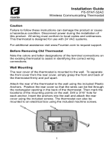
Getting to know your thermostat
THERMOSTAT QUICK REFERENCE
3
Mon
Room
Menu
Set At
SLEEP
LCD Screen
Fan Switch
System Switch
Temperature Setpoint Buttons
User Buttons
Easy Change Battery Door
Tech Set
Sun Mon Tue Wed Thu Fri Sat
Next Step
Min Com On
Com Delay Heat
Set Time
Run Sched
Set Sched
Hold
Prev Step
Menu
Done
WAKE
RETURN
Cool Swing
Room
LEAVE
Hold
SLEEP
PM
Filter
Set At
Displays the user
selected setpoint
temperature.
Days of the week
and time.
Indicates the current
room temperature.
Programmable Time Periods:
This thermostat has 4
programmable time periods
per day.
Button Options
LCD
Hold: Is displayed
when thermostat
program is
permanently
overridden.
Low Battery
Indicator: Replace
batteries when
indicator is shown.
NOTE: The
compressor delay
feature is active if
these icons are
ashing.The
compressor will not
turn on until the 5
minute delay has
elapsed.
System Operation
Indicators:
The , or icon
will display when
the COOL, HEAT, or
(fan) is on.
AM
FAN
AUTO COOLON
OFF HEAT
EMH
1
1
4
2
5
3
6

Mercury Notice:
All of our products are mercury
free. However, if the product you
are replacing contains mercury,
dispose of it properly. Your local
waste management authority
can give you instructions on
recycling and proper disposal.
Caution:
Electrical Hazard
Failure to disconnect the
power before beginning to
install this product can cause
electrical shock or equipment
damage.
SUBBASE INSTALLATION
4
For vertical mount put
one screw top and one
screw bottom.
For horizontal mount put
one screw left and one
screw right.
Vertical mount
Vertical mount
Horizontal mount
Horizontal mount

WIRING
5
1 Turn Off Power to Heating/Cooling System
2 Remove Old Thermostat
or
Heating/cooling system
power switch
Circuit breaker
box
Remove old thermostat but leave wallplate with wires attached.
Do not remove wallplate
Terminal
designation

WIRING
6
ELEC
GAS
3 Label Wires with Tags
Label the wires using the supplied wire labels as you disconnect them.
Wiring Labels
Apply these wiring labels to each wire with the appropriate
terminal designation as you remove it from the existing
thermostat.
B B Y2 Y2
G
R
V/VR
X
AUX
G
R
V/VR
X
AUX
H
RC
W
X1
H
RC
W
X1
C C W/E W/E F F
L L O O P P
RH RH T T U U
W1 W1 W2 W2 W3 W3
X2 X2 Y Y Y1 Y1
4 Separate Wallplate from New Thermostat
Remove wallplate from the new thermostat and mount onto wall.
Wallplate
Wire Labels
Terminal designation

WIRING
7
5 Mount Wallplate for New Thermostat
Mount the new wallplate using the included screws and anchors.
Drill 3/16-in. holes for drywall
Drill 3/16-in. holes for plaster

WIRING
8
6 Connect Wires
Simply match wire labels.
If labels do not match letters on the thermostat, check “Alternate Wiring (Conventional
Systems)” on page 9 and connect to terminal as shown (see notes, below).
SCREW
INSERT WIRES
AND TIGHTEN
SCREWS

Alternate Wiring (Conventional Systems)
If labels do not match letters on the thermostat, check the chart below and connect to terminal as shown
here (See notes, below).
If there is a C or X wire available then you can connect with C terminal. If there is
no C or X wire then no need to connect with C terminal.
If you have a heat pump without auxiliary/backup heat connect either the O or B, not both. If you
do not have a heat pump, do not connect O or B. Wrap bare end of wire with electrical tape.
Place a jumper (piece of wire) between Y and W if you are using a heat pump without auxiliary/
backup heat.
WIRING
9
or or or or or

Caution: Electrical Hazard
Failure to disconnect the power
before beginning to install this
product can cause electrical
shock or equipment damage.
Warning:
All components of the control
system and the thermostat
installation must conform to
Class II circuits per the NEC Code.
1.
If you are replacing a thermostat, make
note of the terminal connections on the
thermostat that is being replaced. In some
cases the wiring connections will not be
color coded. For example, the green wire
may not be connected to the G terminal.
2.
Loosen the terminal block screws. Insert
wires then retighten terminal block screws.
Wiring
Terminal Designations
Heat Pump System
1 HEAT 1 COOL / 2 HEAT 1 COOL
Conventional System
1 HEAT 1 COOL / 2 HEAT 1 COOL
Transformer Power
Transformer Power
Transformer Common
Reversing Valve
Energized in HEAT
Reversing Valve
Energized in COOL
Fan Relay
First Stage of Emergency HEAT
Second Stage of HEAT/
EMERGENCY HEAT
First Stage of HEAT
First Stage of COOL
First Stage of HEAT and COOL
Second Stage of HEAT
Fan Relay
Energized in HEAT
Energized in COOL
Transformer Common
WIRING
10
Installation Tip:
Do not overtighten terminal block screws, as this can damage the terminal block. A damaged
terminalblockcankeepthethermostatfromttingonthesubbasecorrectlyorcausesystem
operation issues. Max Torque = 6in/Ibs.

4
3
2
1
2H/1C Heat Pump System
COMPRESSOR
RELAY
FAN RELAY
COOL REVERSING
VALVE
HEAT REVERSING
VALVE
AUXILIARY
L1(HOT)
L2
Note: In many systems
with no emergency heat
relay a jumper can be
used between E and W2.
WIRING
11
Power supply.
Use either O or B terminals for reversing valve.
Optional 24 VAC common connection when thermostat is used in battery power mode.
Jumper (not supplied).

Typical 2H/1C Heat Pump System with separate emergency heat
Conventional System 1H/1C, 2H/1C
(Heat pump set to OFF in tech settings)
COMPRESSOR
RELAY
EMERGENCY
RELAY
FAN RELAY
COOL REVERSING
VALVE
HEAT REVERSING
VALVE
AUXILIARY
L1(HOT)
L2
COMPRESSOR
RELAY
FAN RELAY
HEAT RELAY
HEAT RELAY 2
L1(HOT)
L2
Note: This
thermostat is only
compatible with
ONE transformer
systems.
WIRING
12

Technician Setup Menu
This thermostat has a technician setup menu
foreasyinstallerconguration.Tosetupthe
thermostat for your particular application:
1. Press MENU button.
2. Press and hold TECH SET button for 3
seconds. This 3 second delay is
designed so that homeowners do not
accidentally access the installer settings.
3. Conguretheinstalleroptionsas
desired using the table on page 14.
Use the or keys to
change settings and the NEXT STEP
or PREV STEP key to move from one
option to another. Note: Only press
DONE key when you want to exit the
Technician Setup options.
Tip
Temperature differential or swing, sometimes called cycle rate, can be customized for this
individual application. For most applications choose a differential setting that is as long as
possible without making the occupants uncomfortable.
TECHNICIAN SETUP MENU
13

TECHNICIAN SETUP MENU
14
Tech Settings
LCD Will Show Adjustment Options
Default
Filter Change
Reminder
Room
Temperature
Calibration
Minimum
Compressor
On Time
This feature will flash FILT in the
display after the elapsed run time
to remind the user to change the
filter. A setting of OFF will disable
this feature.
This feature allows the installer
to change the calibration of the
room temperature display. For
example, if the thermostat reads
70° and you would like it to read
72° then select +2.
This feature allows the installer
to select the minimum run
time for the compressor. For
example: A setting of 4 will force
the compressor to run for at
least 4 minutes every time the
compressor turns on, regardless of
the room temperature.
You can adjust the filter change
reminder from OFF to 2000
hours of runtime in 50 hour
increments. Tap the second
button from the top left side of
the thermostat to display the
current filter elapsed runtime.
You can adjust the room
temperature display to read
3° above or below the factory
calibrated reading.
You can select the minimum
compressor run time from OFF,
3, 4, or 5 minutes. If 3, 4, or 5
is selected, the compressor will
run for at least the selected
time before turning off.
OFF
OFF
0
Next step
Prev step
Next step
Prev step
Next step
Prev step

Tech Settings
LCD Will Show Adjustment Options
Default
TECHNICIAN SETUP MENU
15
Compressor
Short Cycle
Delay
Cooling
Dierential
or Swing
Heating
Dierential
or Swing
The compressor short cycle delay
protects the compressor from
short cycling. This feature will not
allow the compressor to be turned
on for 5 minutes after it was last
turned off.
The differential setting, often
called cycle rate or anticipation, is
adjustable. A smaller differential
setting will cause more frequent
cycles and a larger differential
setting will cause fewer cycles.
The differential setting, often
called cycle rate or anticipation,
is adjustable. A smaller differential
setting will cause more frequent
cycles and a larger differential
setting will cause fewer cycles.
Selecting ON will not allow the
compressor to be turned on
for 5 minutes after the last time
the compressor was switched
off. Select OFF to remove this
delay.
The cooling differential setting
is adjustable from 0.2° to 2°. For
example: A differential setting
of 0.5° will turn the cooling on
at approximately 0.5° above the
setpoint and turn the cooling
off at approximately 0.5° below
the setpoint.
The heating differential setting
is adjustable from 0.2° to 2°. For
example: A differential setting
of 0.5° will turn the heating on
at approximately 0.5° below the
setpoint and turn the heating
off at approximately 0.5° above
the setpoint.
ON
0.5
0.4
Prev step
Prev step
Prev step
Next step
Next step
Next step

Tech Settings
LCD Will Show Adjustment Options
Default
TECHNICIAN SETUP MENU
16
F or C
12 or 24
Hour Clock
Fan
Operation
Select F for Fahrenheit temperature
readout or select C for Celsius
readout.
You can select either a 12 or 24 hour
clock setting.
Select GAS for sytems that control
the fan during a call for heat. Select
ELEC to have the thermostat control
the fan during a call for heat.
Use the
+
and
-
to select 12
or 24 hour clock.
GAS - GS
or
ELEC - EL
F for Fahrenheit
C for Celsius
Prev step
Prev step
Next step
Next step
Prev step
Next step
F
12
GAS

Tech Settings
LCD Will Show Adjustment Options
Default
TECHNICIAN SETUP MENU
17
Program
Options
5d
You can configure this thermostat to
have 7 Day, 5+1+1 programming or
non-programmable.
Note: If 7d is selected, in set schedule
you will program all seven days
individually.
If 5d is selected, in set schedule
you will program Monday – Friday
together and Saturday and Sunday
individually.
If Od is selected the thermostat
becomes non-programmable and
the Set Schedule button goes away
in Menu.
Use the
+
and
-
key to select
7d for 7 Day, 5d for 5+1+1, or
Od for non-programmable.
Prev step
Next step

Attach Faceplate
Align the 4 tabs on the subbase with
corresponding slots on the back of the
thermostat, then push gently until the
thermostat snaps in place.
Battery Installation
Battery installation is optional if thermostat is hardwired (C terminal connected).
ATTACH FACEPLATE & INSTALL BATTERY
18
Insert 2 AAA Alkaline
batteries.
Mon
FAN
AUTO COOLON
HEAT
EMH
OFF
Menu
SLEEP
Set At
Room
/