Setup Guide — RGB 190FV and RGB 192V, cont’d
68-647-50
Rev. A 03 10
Extron USA - West
Headquarters
+800.63 3.9876
Inside USA / Canada Only
+1.714.491.1500
+1.714.491.1517 FAX
Extron USA - East
+800.63 3.9876
Inside USA / Canada Only
+1.919.863.1794
+1.919.863.1797 FAX
Extron Europe
+800.39 87.6673
Inside Europe Only
+31.33.453.4040
+31.33.453.4050 FAX
Extron Asia
+800.7339.8766
Inside Asia Only
+65.638 3.44 00
+65.638 3.46 64 FAX
Extron Japan
+81.3.3511.7655
+81.3.3511.7656 FAX
Extron China
+400.883.1568
Inside China Only
+86.21.3760.1568
+86.21.3760.1566 FA X
Extron Middle East
+971.4.2991800
+971.4.2991880 FAX
© 2010 Extron Electronics. All rights reserved.
Power Supply
Output Cord
SECTION A–A
Ridges
Smooth
A A
Captive
Screw
Connector
Tie
Wrap
3"
16 (5 mm)
Max.
N
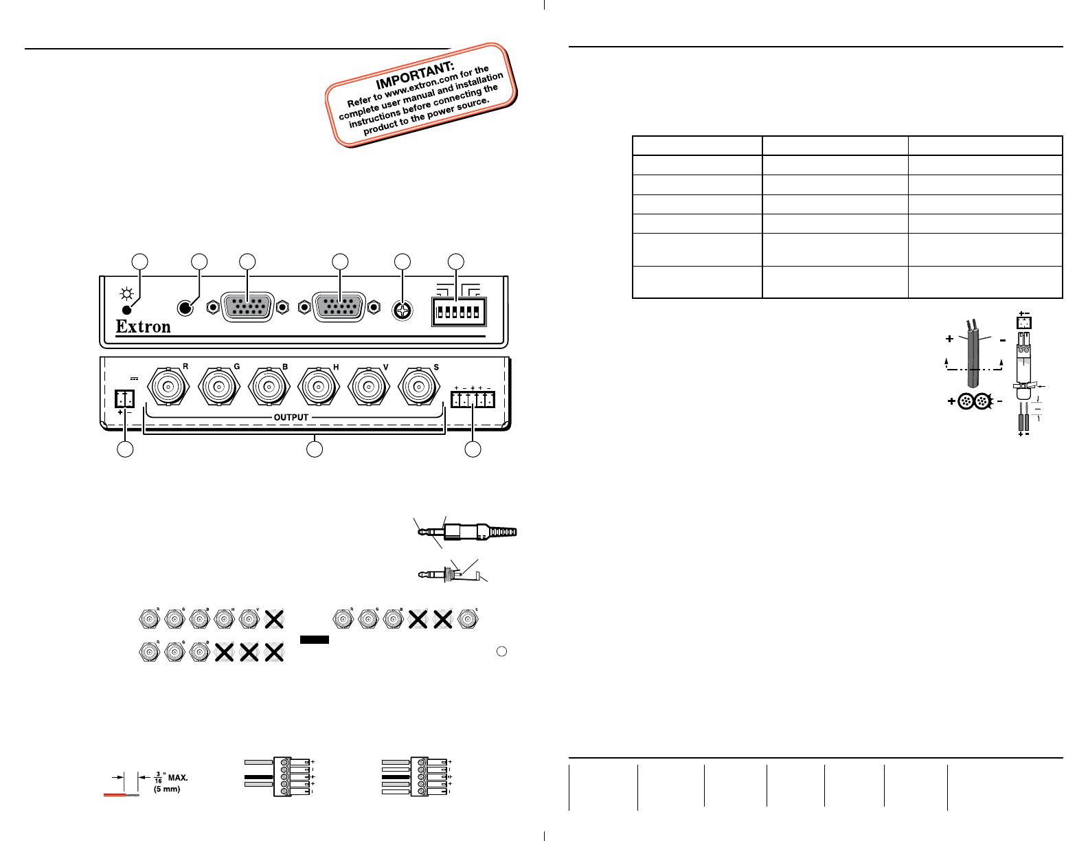
Configure the interface for stereo or mono output using rear panel DIP switch 6 in item
f
,
DIP switches, below. When Mono is selected, the right and left inputs are combined and
placed on the left output connectors.
f
DIP switches — This bank of DIP switches configures the interface as shown in the
following table. Default position for all switches is off (down).
Switch On (up) Off (down)
1 — Level and peaking
0.8 V p-p, 15% peaking Unity (0.7 V) p-p, no peaking
2 — SOG
Sync on green (RGsB) RGBHV or RGBS
3 — Serration pulses
Serration pulses present No serration pulses
4 — DDSP
Bypass sync processing Allow sync processing
5 — No monitor
No local monitor connected
ID bits 4 and 11 grounded
Local monitor connected
6 — Mono audio
(spare for RGB 190FV)
Mono on left channel only Stereo
g
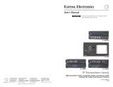
Power connector — Connect an IEC power cord
between the included 12 V power supply and a
100 VAC/240 VAC, 50-60 Hz source. Connect the power
supply to the interface as shown at right.
C
This product is intended to be supplied by a Listed
Power Unit marked “Class 2” or “LPS”, rated
12 VDC, 1.0 A minimum. Always use a power
supply supplied by or specified by Extron. Use of
an unauthorized power supply voids all regulatory
compliance certification and may cause damage to
the supply and the end product. Unless otherwise
stated, the AC/DC adapters are not suitable for use in air handling spaces or in
wall cavities. The installation must always be in accordance with the applicable
provisions of National Electrical Code ANSI/NFPA 70, article 75 and the
Canadian Electrical Code part 1, section 16. The power supply shall not be
permanently fixed to a building structure or similar structure.
Operation
After all devices are powered up, the system is fully operational. If any problems are
encountered, verify that the cables are routed and connected properly. If your problems
persist, call the Extron S
3
Sales & Technical Support Hotline that is closest to you, at the
number shown below.
h
Power indicator —
Amber — Indicates power is applied.
Green — Indicates that power is applied and a sync signal is present on the input.
i
H(orizontal) Shift — While viewing the displayed image, rotate this control to move
the image to the right or left on the screen.
N
DDSP disables the interface’s Horizontal Shift control.
To use the display’s centering controls rather than the interface’s controls, set the DDSP DIP
switch to On (up).
Setup Guide — RGB 190FV and RGB 192V
This guide provides quick start instructions for an experienced
installer to set up and operate Extron
®
RGB 190FV and
RGB 192V analog computer-video interfaces. The
RGB 192V also has audio capabilities.
Installation
Step 1 — Mounting
Turn off or disconnect all equipment power sources and mount the interface as required.
With optional mounting kits, it can be mounted under or through a desk or other furniture.
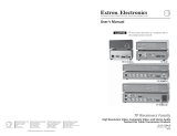
Step 2 — Connections
N
The drawing below shows an RGB 192V. With the exception of audio features (marked with
an asterisk [*] in the callout), the features described in step 2 apply to both models.
H - S H I F T
S E R R
D D S P
N O M O N .
M . A U D I O
S O G
L E V E L
R G B 1 9 2
C O M P U T E R
I N P U T M O N I TO R
L/MONO
R
AUDIO
AUDIO
1
ON
2
3
4
5
6
POWER
12-15V
1A MAX.
5*7
8 2*
4
1 3 69
a
Computer Input — Connect a computer-video source to this female 15-pin HD connector.
b
Audio input (RGB 192V only) — Connect an unbalanced
stereo audio source to this 3.5 mm mini stereo jack for
unbalanced audio input.
c
Monitor connector — If desired, connect a local monitor or
other device to this female 15-pin HD connector.
d
BNC output connectors — Connect a display to these rear
panel BNC connectors as shown in the figure below.
RGBHV
RGBS
RGsB
For RGsB video, also select the
SOG option using DIP s
NOTE
6
e
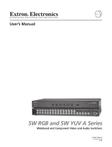
Stereo audio output connector (RGB 192V only) — Connect an audio device, such
as powered speakers, to this 3.5 mm, 5-pole captive screw connector for balanced or
unbalanced stereo or mono audio output.
C
For unbalanced audio output, connect the sleeve(s) to the ground contact.
DO NOT connect the sleeve(s) to the negative (-) contacts).
L R
Balanced Stereo OutputUnbalanced Stereo Output
Tip
Ring
Sleeve (s)
Tip
Ring
Sleeve(s)
L R
Tip
Tip
NO GROUND HERE.
NO GROUND HERE.
Do not tin the wires!
Tip (Left) Sleeve (Gnd)
Tip (Left)
Ring (Right)
Sleeve
(Gnd)