MPA 152

Extron electronic MPA 152 User manual

  • Hello! I am an AI chatbot trained to assist you with the Extron electronic MPA 152 User manual. I’ve already reviewed the document and can help you find the information you need or explain it in simple terms. Just ask your questions, and providing more details will help me assist you more effectively!
68-1320-02 Rev. B
11 12
ENERGY STAR
®
Qualified Stereo Mini Power Amplifier
MPA 152
User Guide
Audio
Safety Instructions • English
WARNING: This symbol, D, when used on the product, is intended
to alert the user of the presence of uninsulated dangerous voltage
within the product’s enclosure that may present a risk of electric
shock.
ATTENTION: This symbol, I, when used on the product, is
intended to alert the user of important operating and maintenance
(servicing) instructions in the literature provided with the equipment.
For information on safety guidelines, regulatory compliances, EMI/EMF
compatibility, accessibility, and related topics, see the Extron Safety and
Regulatory Compliance Guide, part number 68-290-01, on the Extron
website, www.extron.com.
Instructions de sécurité • Français
AVERTISSEMENT: Ce pictogramme, D, lorsqu’il est utilisé sur
le produit, signale à l’utilisateur la présence à l’intérieur du boîtier
du produit d’une tension électrique dangereuse susceptible de
provoquer un choc électrique.
ATTENTION: Ce pictogramme, I, lorsqu’il est utilisé sur le produit,
signale à l’utilisateur des instructions d’utilisation ou de maintenance
importantes qui se trouvent dans la documentation fournie avec le
matériel.
Pour en savoir plus sur les règles de sécurité, la conformité à la
réglementation, la compatibilité EMI/EMF, l’accessibilité, et autres sujets
connexes, lisez les informations de sécurité et de conformité Extron,
réf. 68-290-01, sur le site Extron, www.extron.fr.
Sicherheitsanweisungen • Deutsch
WARNUNG: Dieses Symbol D auf dem Produkt soll den Benutzer
darauf aufmerksam machen, dass im Inneren des Gehäuses dieses
Produktes gefährliche Spannungen herrschen, die nicht isoliert sind
und die einen elektrischen Schlag verursachen können.
VORSICHT: Dieses Symbol I auf dem Produkt soll dem Benutzer in
der im Lieferumfang enthaltenen Dokumentation besonders wichtige
Hinweise zur Bedienung und Wartung (Instandhaltung) geben.
Weitere Informationen über die Sicherheitsrichtlinien, Produkthandhabung,
EMI/EMF-Kompatibilität, Zugänglichkeit und verwandte Themen finden Sie
in den Extron-Richtlinien für Sicherheit und Handhabung (Artikelnummer
68-290-01) auf der Extron-Website, www.extron.de.
Instrucciones de seguridad • Español
ADVERTENCIA: Este símbolo, D, cuando se utiliza en el producto,
avisa al usuario de la presencia de voltaje peligroso sin aislar dentro
del producto, lo que puede representar un riesgo de descarga
eléctrica.
ATENCIÓN: Este símbolo, I, cuando se utiliza en el producto, avisa
al usuario de la presencia de importantes instrucciones de uso y
mantenimiento recogidas en la documentación proporcionada con
el equipo.
Para obtener información sobre directrices de seguridad, cumplimiento
de normativas, compatibilidad electromagnética, accesibilidad y
temas relacionados, consulte la Guía de cumplimiento de normativas
y seguridad de Extron, referencia 68-290-01, en el sitio Web de Extron,
www.extron.es.
Chinese Simplified(简体中文)
警告D产品上的个标志意在警用户该产品机壳内有暴露的危险
电 压 ,有 触 电 危 险
注意I 产品上的这个标志意在提示用户设备随附的用户手册中有
重要的操作和维护(维修)说明。
关于我们产品的安全指南、遵循的规范、
EMI/EMF 的兼容性、无障碍
使用的特性等相关内容,敬请访问
Extron 网站 www.extron.com,参见 Extron
安全规范指南,产品编号
68-290-01
Chinese Traditional(繁體中文)
警告: D品上使用此符號是為提醒使用產品機殼內存在著
能會導致觸電之風險的未絕緣危險電壓
意I 若產品使用此符號是為提醒使用
有關安全性指導方針、法規遵守、EMI/EMF 相容性、存取範圍和相關主題的詳細
資訊,請瀏覽 Extron 網站:www.extron.com,然後參閱《Extron 安全性與法
規遵守手冊》,準則編號 68-290-01。
Japanese
警告: この D 製品上に表示されている場合は、筐体内に絶縁され
いない圧がれ、電のがあること示しています
注意: この I が製品上に表示されている場合は、本機の取扱説明書に
されている重要な作と保()のについてユザーの
注意を喚起するものです
安全上のご注意、法規厳守、EMI/EMF適合性、その他の関連項目
スト イト www.extron.comより
Extron Safety and Regulatory Compliance Guide(P/N 69-290-01) くだ
Korean
경고: 이 기호 D, 가 제품에 사용될 경우, 제품의 인클로저 내에 있는
접지되지 않은 위험한 전류로 인해 사용자가 감전될 위험이 있음을
경고합니다.
주의: 이 기호 I, 가 제품에 사용될 경우, 장비와 함께 제공된 책자에 나와
있는 주요 운영 및 유지보수(정비) 지침을 경고합니다.
전 가이드인, 규제 준수, EMI/EMF 호성, 접근성, 그리고 관련
목에 대한 자세한 내용은 Extron 웹 사이트(www.extron.com)의
Extron 안전 및 규제 준수 안내서, 68-290-01 조항을 참하십시오.
Safety Instructions
FCC Class B Notice
This equipment has been tested and found to comply with the limits for a
ClassB digital device, pursuant to part15 of the FCC rules. These limits provide
reasonable protection against harmful interference in a residential installation. This
equipment generates, uses, and can radiate radio frequency energy and, if not installed
and used in accordance with the instructions, may cause harmful interference to radio
communications. There is no guarantee that interference will not occur. If this equipment
does cause interference to radio or television reception, which can be determined by turning
the equipment off and on, you are encouraged to try to correct the interference by one or
more of the following measures:
• Reorient or relocate the receiving antenna.
• Increase the separation between the equipment and receiver.
• Connect the equipment into an outlet on a circuit different from that to which the
receiver is connected.
• Consult the dealer or an experienced radio/TV technician for help.
NOTES:
• ThisunitwastestedwithshieldedI/Ocablesontheperipheraldevices.
ShieldedcablesmustbeusedtoensurecompliancewithFCCemissionslimits.
• Formoreinformationonsafetyguidelines,regulatorycompliances,EMI/EMF
compatibility,accessibility,andrelatedtopics,seethe“Extron Safety and
Regulatory Compliance Guide”ontheExtronwebsite.
Specications Availability
Product specifications are available on the Extron website, www.extron.com.
Conventions Used in this Guide
Notications the following are used:
ATTENTION: Attention indicates a situation that may damage or destroy the product
or associated equipment.
NOTE: A note draws attention to important information.
Copyright
© 2012 Extron Electronics. All rights reserved.
Trademarks
All trademarks mentioned in this manual are the properties of their respective owners.
Contents
Specifications Availability ..................................iii
Introduction............................................................ 1
Important Safety Instructions .............................. 1
About the MPA 152 ............................................ 2
MPA 152 Features .............................................. 2
Panels and Cabling .............................................. 4
MPA 152 Rear Panel Features ............................ 4
Power Connector ........................................... 5
Audio Inputs ................................................... 6
Remote Control .............................................. 7
Audio Output .................................................. 8
Setup and Operation ............................................ 9
Front Panel Features ........................................... 9
Setting Input Level .......................................... 9
Setting Bass and Treble ................................ 10
Remote Control Options ................................... 10
Troubleshooting ................................................ 11
Amplifier Fails to Exit Standby Mode
Promptly ...................................................... 11
Amplifier Enters Standby Mode Too Early ...... 11
Reference Material ............................................. 12
Included Parts .................................................. 12
Optional Accessories ........................................ 12
Mounting .......................................................... 13
Plenum Placement ........................................ 13
Tabletop Placement ...................................... 13
Rack Mounting ............................................. 14
Back of the Rack Mounting .......................... 15
Under-desk Mounting ................................... 15
Pole Mounting .............................................. 15
ZipClip
200 Mounting ................................. 15
MPA 152 • Contents v
MPA 152 • Contents vi
Introduction
This manual contains information about the Extron MPA 152 mini power amplifier with
instructions for experienced installers on how to install, configure, and operate the
equipment. Unless otherwise specified, references in this manual to the “amplifier” or “MPA”
relate to the features or operation of the MPA 152.
This section provides the following information:
• Important Safety Instructions
• About the MPA 152
• MPA 152 Features
Important Safety Instructions
1. Read these instructions.
2. Keep these instructions.
3. Heed all warnings.
4. Follow all instructions.
5. Do not use this apparatus near water.
6. Clean only with dry cloth.
7. Do not block any ventilation openings. Install in accordance with the instructions of the
manufacturer.
8. Do not install near any heat sources such as radiators, heat registers, stoves, or other
apparatus (including amplifiers) that produce heat.
9. Do not defeat the safety purpose of the polarized or grounding-type plug. A polarized
plug has two blades with one wider than the other. A grounding type plug has two
blades and a third grounding prong. The wide blade or the third prong are provided
for safety. If the provided plug does not fit into the outlet, consult an electrician for
replacement of the obsolete outlet.
10. Protect the power cord from being walked on or pinched particularly at plugs,
convenience receptacles, and the point where they exit from the apparatus.
11. Only use attachments or accessories specified by the manufacturer.
12.
Use only with the cart, stand, tripod, bracket, or table specified by the
manufacturer, or sold with the apparatus. When a cart is used, use caution
when moving the cart/apparatus combination to avoid injury from tip-over.
13. Unplug this apparatus during lightning storms or when unused for long periods of time.
14. Refer all servicing to qualified service personnel. Servicing is required when the
apparatus has been damaged in any way, such as if the power-supply cord or plug
is damaged, liquid has been spilled or objects have fallen into the apparatus, the
apparatus has been exposed to rain or moisture, does not operate normally, or has
been dropped.
MPA 152 • Introduction 1
About the MPA 152
The MPA 152 is an ENERGY STAR
®
qualified, high performance, compact, power amplifier.
It delivers up to 15watts(rms) per channel stereo or dual mono into a 4 ohm sound system,
or 8watts(rms)per channel into an 8 ohm system.
Front panel controls allow easy adjustment of bass and treble volume and input level.
The unit meets UL smoke and fire code for in-the-ceiling installations and can be stored in
the plenum space of the roof.
Alternatively, the units can be mounted on a tabletop, in a rack, under a desk, or in a
projector mounting kit.
POWER
12V
3A MAX
OUTPUT
4/8
OHMS
INPUTS
L
R
L
R
REMOTE
VOL/MUTE
10V
50mA
L
MPA 152
R
C
US
LISTED
17TT
AUDIO/VIDEO
APPARATUS
CLASS 2 WIRING
DO NOT GROUND
OR SHORT
SPEAKER OUTPUTS!
Extron
CONFIG
DISPLAY
VOLUME
1
2
3
4
ON
OFF
MLC 104 IP PLUS
VIDEO
AUX
VIDEO
PC
IMAGE
MUTE
Extron
MPA 152
Mini Power
Amplier
RGBHV
S-Video
Audio
Audio
Audio
Audio
Video
DVD/VCR
Combo
Laptop
Projector
RS-232 or
IR Projector
control
Extron
MLC 104 IP Plus
MediaLink
Controller
with IP Link
Extron
SM 3
Full-range
Speakers
Figure 1. Typical Application for the MPA 152
MPA 152 Features
ENERGY STAR® qualified amplifier — The MPA 152 is available as an ENERGY STAR
qualified amplifier, with an auto power-down feature that automatically places the amplifier
into standby after 25 minutes of inactivity, dramatically reducing power consumption.
Extron Patented CDRS™ - Class D Ripple Suppression — CDRS is an Extron
Patented technology that provides a smooth, clean audio waveform and an improvement
in signal fidelity over conventional Class D amplifier designs. CDRS eliminates the high
frequency switching ripple characteristic of Class D amplifiers, a source of RF emissions
which can interfere with sensitive AV equipment such as wireless microphones.
Ripple Steering technology — Produces cleaner, low-emission, audio output signals.
Fixed switching frequency — Switches at a frequency below the AM band, which
reduces the chance of radio interference.
Three audio inputs — Accepts one balanced or unbalanced input pair (captive screw),
one unbalanced pair (RCA), and one unbalanced pair (TRS), providing up to three right and
three left channel inputs. All three right inputs are summed to produce a single right output;
all three left inputs are summed to produce a single left output.
MPA 152 • Introduction 2
Stereo or Dual Mono toggle switch — Allows the user to choose between stereo output
or to combine the left and right outputs and produce dual mono outputs.
Up to 15 watts (rms) per channel stereo output — Delivers up to 15watts(rms) per
channel, stereo or dual mono, into a 4 ohm speaker system or up to 8watts(rms) per
channel into an 8ohm system.
Front panel controls — Input level, bass and treble are easily adjusted from the front
panel.
Quick-plug speaker outputs — Speaker output is on a captive screw connector for quick
installation.
Volume and mute remote control — A rear panel, three-pin captive screw remote input
connector allows remote adjustment of volume and muting.
Always-on clip limiting — Reduces gain automatically to prevent amplifier clipping.
Compact size — The amplifiers are housed in a 1U high, 3 inch deep, quarter rack metal
enclosure, which offers flexible mounting options.
UL 2043 plenum rated — The MPA 152 meets UL 2043 for smoke and heat release
for installation within a plenum airspace above a drop ceiling (power supply excluded).
Above-the-ceiling placement conceals the amplifier to prevent theft, and is convenient for
installing equipment when space inside the room is limited.
MPA 152 • Introduction 3
Panels and
Cabling
This section discusses the MPA 152 rear panel features and cabling.
MPA 152 Rear Panel Features
The rear panel of the MPA 152 (shown in Figure 2 below) allows the user to connect power,
audio input, speakers, and remote control.
POWER
12V
0.6A MAX
OUTPUT
4/8
OHMS
CLASS 2 WIRING
DO NOT GROUND
OR SHORT
SPEAKER OUTPUTS!
INPUTS
L
R
L
R
REMOTE
VOL/MUTE
10V 50mA
L
MPA 152
R
1 2 3 654
Figure 2. MPA 152 Rear Panels Features
MPA 152 • Panels and Cabling 4
Power Connector
a
Power connector — The MPA 152 ships with the Extron 24 W PS 1220 desktop
power supply (part number 70-967-01).
ATTENTION: When the PS 1220 power supply is connected to the MPA 152, it
must not be shared with any other devices.
Power
Receptacle
DC Power Cord
Captive Screw
Connector
POWER
12V
0.6 A MAX
MPA 152
Amplifier
DC Power
Outputs
DO NOT USE
AC Power Cord
Tie
Wrap
Captive Screw
Connector
Power Supply
Output Cord
PS 1220
Power Supply
Figure 3. Power Connector
Connect the two-pole, 3.5 mm captive screw connector from the power supply to
the power socket on the rear panel of the MPA152, as shown above. Ensure the
connections have the correct polarity.
ATTENTION:
• AlwaysuseapowersupplysuppliedbyorspecifiedbyExtron.Useofan
unauthorizedpowersupplyvoidsallregulatorycompliancecertificationand
maycausedamagetothesupplyandtheendproduct.
• Suitableforuseinenvironmentalairspaceinaccordancewith
Section300.22.CoftheNationalElectricalCode,andSections2-128,
12-010(3)and12-100oftheCanadianElectricalCode,Part1,C22.1.
• Unlessotherwisestated,theAC/DCadaptersarenotsuitableforuseinair
handlingspacesorinwallcavities.Thepowersupplyistobelocatedwithin
thesamevicinityastheExtronAVprocessingequipmentinanordinary
location,PollutionDegree2,securedtotheequipmentrackwithinthe
dedicatedcloset,podium,ordesk.
• Theinstallationmustalwaysbeinaccordancewiththeapplicableprovisionsof
NationalElectricalCodeANSI/NFPA70andtheCanadianElectricalCode.The
powersupplyshallnotbepermanentlyfixedtobuildingstructureorsimilar
structure.
• Thelengthoftheexposedwiresinthestrippingprocessiscritical.Theideal
lengthis3/16inches(5mm).Anylongerandtheexposedwiresmaytouch,
causingashortcircuitbetweenthem.Anyshorterandthewirescanbeeasily
pulledouteveniftightlyfastenedbythecaptivescrews.
NOTE: Donottinthewires.Tinnedwiredoesnotholditsshapeandcanbecome
looseovertime.
MPA 152 • Panels and Cabling 5
Audio Inputs
INPUTS
L
R
L
R
Figure 4. Audio Inputs
b
RCA input connectors — These two connectors (left
and right) accept unbalanced, line level audio signals.
The input can be stereo (using two RCA jacks) or mono
(using a single RCA jack plugged into the left socket). If
unused, the connectors automatically terminate to lower
the noise floor.
c
3.5 mm stereo input — This Tip-Ring-Sleeve (TRS)
connector accepts unbalanced, line level audio signals.
If unused, the connector automatically terminates to
lower the noise floor.
d
Balanced or unbalanced audio input connector — This
5-pole, 3.5 mm captive screw input accepts balanced or
unbalanced, mono or stereo, line level signals. See the
attention and note on page 5 for important information about
connecting wires to captive screw connectors.
The three left channel inputs (RCA, TRS and captive screw) are summed to provide a
single left channel output. The three right channel inputs are summed to provide a single
right channel output.
Depending on the position of the front panel toggle switch (see figure 7 on page 9), the
right and left channels may be output as a stereo signal, or averaged and output as a
dual mono signal.
Tip (+)
Sleeve ( )
RCA Connector
Sleeve ( )
Ring (R)
Tip (L)
3.5 mm Stereo
Plug Connector
Unbalanced Stereo Input
Balanced Stereo Input
Tip
Ring
Tip
Ring
LR
Sleeves
Tip
Sleeve
Sleeve
Tip
LR
MPA 152 • Panels and Cabling 6
Remote Control
e
Remote input connector — This 3-pin, captive screw connector
allows a wall-mounted audio controller or MediaLink product to
control volume and mute levels remotely.
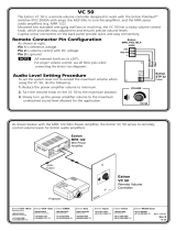
Wiring for remote control
Options for remote control include the Extron VC50, VCM100AAP, VCM100MAAP,
VCM 200 series, and MLAVC10 Plus. For information about part numbers, see the list of
Optional Accessories on page 12. Third party 10k potentiometer volume controllers can
also be connected to this port.
Figure 5 and the instructions below, show the wiring for the VCM 100 MAAP. Wiring other
remote control connectors is similar.
GND (Pin 3)
Volume Pot
10K Ohms
2K
Vol/Mute
(Pin 2)
10 V (Pin 1)
Mute
Switch
REMOTE
Figure 5. Remote Control Wiring
• Pin 1 is 10 VDC reference voltage.
• Pin 2 (Vol/Mute) has two functions:
a. It can be used as a variable voltage input between 0 and 10 VDC, with 0 V giving
full attenuation and 10 V giving maximum volume.
b. It can be used for remote control muting. Sound is muted while the mute pin is
shorted to ground.
• Pin 3 is ground.
NOTE: All nominal levels are at ± 10%.
Controlling multiple ampliers with one volume controller
Several MPA 152 units can be daisy-chained so that one volume controller can
simultaneously regulate the volume of all the amplifiers.
NOTES:
• Asadditionalamplifiersareaddedtothedaisychain,thesensitivityofthe
volumepotentiometerwillchange.Themaximumvolumelevel(fullyclockwise)
willnotbeaffected.Howevertheeffectivenessoftheminimumvolumelevel
(fullycounterclockwise)inreducingthevolumetoinaudiblelevelsdecreasesas
moreamplifiersareaddedtothedaisychain.
• WhenmorethantwoMPAsareattachedtothechain,soundmaybeginto
beheardevenifthelevelshavebeensettotheirlowest.Themutingofthe
outputhowevercanberemediedwithacontactclosurebuttonattached
betweentheVol/MuteandGroundpinofthefirstMPAinthechain.
REMOTE
V
OL/MUTE
10V50mA
MPA 152 • Panels and Cabling 7
To regulate multiple amplifiers with a single volume controller, follow these instructions:
1. Attach all three pins of the volume controller to the corresponding pins on the first
MPA152 unit only (ground to ground; Vol/Mute to Vol/Mute; and 10 V to 10 V).
2. Use jumper wires to connect the Vol/Mute pins of the first amplifier and each successive
amplifier.
3. Use jumper wires to connect the ground pins of the first amplifier and each successive
amplifier.
10V
VOL/MUTE
50mA10V
VOL/MUTE
50mA 10V
VOL/MUTE
50mA
10V
VOL/MUTE
Extron
VCM 100 AAP
Extron
MPA 152
daisy chain
Figure 6. Regulating Multiple Amplifiers with a Single Volume Controller
NOTE: The 10V pin of the volume controller connects to the first MPA 152 only.
There are no jumper wires linking it to subsequent amplifiers.
Audio Output
f
Speaker connector — This 4-pole, 5 mm captive screw
connector is used to connect the amplifier to the speakers.
All right channel input signals are summed to produce a
single, right channel output; likewise, all left channel input
signals are summed to produce a single, left channel output
If the front panel switch (see figure 7 on page 9) is set to stereo, the output will be
stereo; if the front panel switch is set to dual mono, the right and left channels will be
mixed (summed and divided by two) for a dual mono output.
With an 8 ohm load, the amplifier produces up to 8watts per channel. With a 4 ohm
load, the amplifier produces up to 15watts per channel.
See the attention and note on page 5 for important information about connecting
wires to captive screw connectors.
ATTENTION: Do not short the + and – outputs to each other, as this will damage
the amplifier.
OUTPUT
4/8
OHMS
LR
MPA 152 • Panels and Cabling 8
Setup and
Operation
This section discusses:
• Front Panel Features
• Remote Control Options
• Troubleshooting
Front Panel Features
This section describes how to use the controls on the MPA 152 front panel (shown in
figure7 below) to configure the amplifier and how to set up the remote control options.
BASSLEVEL TREBLE
MINI POWER AMPLIFIER
MPA 152
STEREO
DUAL
MONO
3
2
1
Figure 7. MPA 152 Front Panel
a
Power LED — The LED lights green when the MPA 152 unit is receiving power and
active. It lights amber when the unit is on standby (after 25 minutes of inactivity).
b
Stereo or Dual Mono toggle switch — Allows the user to choose between stereo
output for stereo applications (default) or dual mono output for mono applications.
c
Potentiometers — Three front panel potentiometers are used to optimize input level,
bass, and treble settings.
Setting Input Level
Adjust the MPA 152 input level as follows:
1. Unplug the remote plug from the unit.
2. Turn the Level potentiometer fully counterclockwise to its minimum setting.
3. Set the volume of the audio source to its maximum level. No sound should come out.
4. Slowly increase the MPA 152 level until sound distortion starts to occur. Lower the level
slightly until the distortion disappears. This setting will ensure that, whatever the volume
setting of the audio source, no clipping will occur.
MPA 152 • Setup and Operation 9
Setting Bass and Treble
Adjust the MPA 152 bass and treble as follows:
1. Use the Bass potentiometer to increase or decrease the bass shelving ±10 dB at 80 Hz
and below.
2. Use the Treble potentiometer to increase or decrease the treble shelving ±10 dB at
10kHz and above.
NOTE: Turning the Bass or Treble potentiometers counterclockwise will decrease the
output at the specified frequencies. Turning the potentiometers clockwise will increase
the output. When the potentiometer is in the center, flat response is achieved.
Remote Control Options
POWER
12V
3A MAX
OUTPUTS
4/8
Ohms
INPUTS
L
R
L
R
REMOTE
10V
VOL/MUTE
L
MPA 122 PLUS
R
C
US
LISTED 17TT
AUDIO/VIDEO
APPARATUS
PC
Projector
8 ohm Ceiling
Speakers
in Parallel
VGA w/
Audio Cable
VCR
Composite
Audio RCA
Variable
Audio
Output
ComLink
IR Remote
Extron
MLC 104 IP
Controller
Extron
VCM 100 AAP
Volume/Mute Controller
Extron
MPA 152
Mini Power Amplifier
1
2
3
CONFIG
PROJECTOR
VOLUME
MLC 104 IP
1
2
3
4
ON
OFF
MUTE
VOLUME
VCM 100 AAP
DVD
S-video
Audio RCA
Figure 8. Typical Application for the MPA 152, Using Remote Control
a
Using the IR remote for the projector — When using a projector with variable audio
outputs, connect the projector audio output to the MPA 152 audio input. Use the IR
remote for the projector to control the volume of the projector, which effectively controls
the volume of the MPA 152.
b
Extron volume controllers — Extron provides a range of volume and mute controllers
that offer a remote control option for use with a projector that lacks variable audio
outputs. These options control the MPA 152 volume directly. See page 7 for more
information about “Wiring for remote control.”
c
Using a MediaLink
®
Controller — For a projector with variable audio output, connect
the projector audio output to the MPA 152 audio input. Use a MediaLink controller to
adjust the volume of the projector via RS-232. MediaLink controllers can also use the IR
remote to adjust the volume of the projector and thus the input to the amplifier.
MPA 152 • Setup and Operation 10
Troubleshooting
Under different circumstances, the front panel LED lights green or amber, which provides
diagnostic information.
Amplier Fails to Exit Standby Mode Promptly
Power LED
Color
Problem Description Problem Solution
Amber No output signal. • No input detected: verify that there is an
input signal.
If a signal is present, raise the level of the
source signal.
Green No output signal. • The amplifier may be in mute mode. Check
the remote port.
Green or
Amber
Slow to exit standby
mode when a signal is
present.
• The input signal may be too weak. Raise
the level of the source signal.
Amplier Enters Standby Mode Too Early
Power LED
Color
Problem Description Problem Solution
Green or
Amber
Enters standby mode
early.
• The input signal may be too weak. Raise
the level of the source signal.
MPA 152 • Setup and Operation 11
Reference Material
This section provides information about:
• Included Parts
• Optional Accessories
• Mounting
Included Parts
Description Part Number
MPA 152 60-844-02
PS 1220 external 12 V, 2 A power supply 70-967-01
IEC power cord
(1) 4-pole 5 mm terminal block plug
(1) 5-pole 3.5 mm captive screw plug
(1) 3-pole 3.5 mm captive screw plug
(1) 2-pole 3.5 mm power captive screw plug
MPA 152 Setup Guide
Optional Accessories
Description Part Number
RSB 123 (3.5 inch deep, 1U basic rack shelf) 60-604-21
RSF 123 (3.5 inch deep, 1U rack shelf kit) 60-190-20
RSB 126 (6 inch deep, 1U basic rack shelf) 60-604-11
RSU 126 (6 inch deep, 1U rack shelf kit) 60-190-10
RSB 129 (9.5 inch deep, 1U basic rack shelf) 60-604-02
RSU 129 (9.5 inch deep, 1U rack shelf kit) 60-190-01
MBB 100 Back of rack mounting kit 70-367-01
MBU 125 Under-desk mounting kit 70-077-01
ZipClip
200 101-001-01
PMK 100 Pole mount kit 70-217-01
PMK 300 Pole mount kit 70-374-01
PMK 350 Pole mount kit 70-563-03
MPA 152 • Reference Material 12
Description Part Number
VC 50 Volume control wall plate 70-530-02
VCM 100 AAP Volume/mute - AAP 70-396-11
VCM 100 MAAP Volume/mute - MAAP 70-397-11
VCM 200 D Volume control wall plate 70-883-02
VCM 200 EU Volume control wall plate 70-884-05
VCM 200 MK Volume control wall plate 70-884-03
MLA VC10 Plus Volume control module 60-1090-01
SM 3 compact, full range speakers with SpeedMount
(Black, White) 42-133-xx
SI 3CT LP full range ceiling speakers 42-103-03
SI 26 two way surface mount speakers (Black, White) 42-072-xx
SI 26X two way open back ceiling speakers 42-067-03
FF 120T Flat Field
®
speakers 42-120-13
FF 220T Flat Field speakers 42-141-03
SPK14/1000 Non-Plenum 1000 feet (300 m) spool 22-152-03
SPK14P/1000 Plenum 1000 feet (300 m) spool 22-155-03
SPK16/1000 Non-Plenum 1000 feet (300 m) spool 22-151-03
SPK16P/1000 Plenum 1000 feet (300 m) spool 22-154-03
SPK18/1000 Non-Plenum 1000 feet (300 m) spool 22-150-03
SPK18P/1000 Plenum 1000 feet (300 m) spool 22-153-03
Mounting
Plenum Placement
The MPA 152 amplifier complies with Section 300.22 (c) of the National Electrical Code and
is suitable for use in an Environmental Air Space. It can be installed in the ceiling, out of
sight, with reduced risk of theft.
ATTENTION: Although the amplifier is plenum rated, the power supply provided with
it is not. The power supply must not be placed in the plenum space. Cables to and
from the amplifier must also be plenum rated.
Tabletop Placement
Attach the four provided rubber feet to the bottom of the unit and place it in any convenient
location.
MPA 152 • Reference Material 13
Rack Mounting
UL Guidelines for Rack Mounting
The following Underwriters Laboratories (UL) guidelines are relevant to the safe installation of
this product in a rack:
1. Elevated operating ambient temperature — If the unit is installed in a closed or
multi-unit rack assembly, the operating ambient temperature of the rack environment
may be greater than room ambient temperature. Therefore, install the equipment in
an environment compatible with the maximum ambient temperature (TMA: +122 °F,
+50°C) specified by Extron.
2. Reduced air flow — Install the equipment in the rack so that the equipment gets
adequate air flow for safe operation.
3. Mechanical loading — Mount the equipment in the rack so that uneven mechanical
loading does not create a hazardous condition.
4. Circuit overloading — Connect the equipment to the supply circuit and consider the
effect that circuit overloading might have on overcurrent protection and supply wiring.
Appropriate consideration of the equipment nameplate ratings should be used when
addressing this concern.
5. Reliable earthing (grounding) — Maintain reliable grounding of rack-mounted
equipment. Pay particular attention to supply connections other than direct connections
to the branch circuit (such as the use of power strips).
Rack Mounting Procedure
The unit can be mounted on any of these optional Extron rack systems:
• RSF 123 — 3.5 inch deep, 1U universal rack shelf kit (part number 60-190-20)
• RSB 123 — 3.5 inch deep, 1U basic rack shelf (part number 60-604-21)
• RSU 126 — 6 inch deep, 1U universal rack shelf kit (part number 60-190-10)
• RSB 126 — 6 inch deep, 1U basic rack shelf (part number 60-604-11)
• RSU 129 — 9.5 inch deep, 1U universal rack shelf kit (part number 60-190-01)
• RSB 129 — 9.5 inch deep, 1U basic rack shelf (part number 60-604-02)
To mount the amplifier on a rack shelf, follow the instructions provided with the shelf
accessories.
MPA 152 • Reference Material 14
ATTENTION: Use only the two holes indicated in the diagram below for mounting the
MPA152. The other four holes anchor stand-offs for the internal circuit boards; using
them may damage the amplifier and will not provide secure mounting for the unit.
1.44"
3.67"
#4-40 Thread Thru
Rack Mounting
#4-40 Thread Thru
Rack Mounting
Back of the Rack Mounting
The unit can be mounted at the back of a rack rail using the MBB 100 mounting kit
(partnumber70-367-01). Follow the instructions provided with the kit.
Under-desk Mounting
Mount the unit under a desk or podium, using the optional Extron MBU 125 under-desk
mounting kit (partnumber70-077-01) by following the instructions provided with the
MBU125 kit.
Pole Mounting
The amplifier can be mounted above a projector using any of these optional Extron Pole
Mounting Kits:
• PMK 100 Pole mount kit (part number 70-217-01)
• PMK 300 Pole mount kit (part number 70-374-01)
• PMK 350 Pole mount kit (part number 70-563-03)
Follow the instructions provided with the kit.
ZipClip
200 Mounting
The unit can be mounted under furniture or to a rack rail using the ZipClip 200
(partnumber101-001-01). Follow the instructions provided with the mounting kit.
MPA 152 • Reference Material 15
/