Page is loading ...

ISM 482 & ISM 182
Integration Scaling Matrix Switchers
68-576-01 Rev. C
11 04

This symbol is intended to alert the user of important operating and maintenance
(servicing) instructions in the literature provided with the equipment.
This symbol is intended to alert the user of the presence of uninsulated dangerous
voltage within the product's enclosure that may present a risk of electric shock.
Caution
Read Instructions • Read and understand all safety and operating instructions before using the
equipment.
Retain Instructions • The safety instructions should be kept for future reference.
Follow Warnings • Follow all warnings and instructions marked on the equipment or in the user
information.
Avoid Attachments • Do not use tools or attachments that are not recommended by the equipment
manufacturer because they may be hazardous.
Warning
Power sources • This equipment should be operated only from the power source indicated on the
product. This equipment is intended to be used with a main power system with a grounded
(neutral) conductor. The third (grounding) pin is a safety feature, do not attempt to bypass or
disable it.
Power disconnection • To remove power from the equipment safely, remove all power cords from
the rear of the equipment, or the desktop power module (if detachable), or from the power
source receptacle (wall plug).
Power cord protection • Power cords should be routed so that they are not likely to be stepped on or
pinched by items placed upon or against them.
Servicing • Refer all servicing to qualified service personnel. There are no user-serviceable parts
inside. To prevent the risk of shock, do not attempt to service this equipment yourself because
opening or removing covers may expose you to dangerous voltage or other hazards.
Slots and openings • If the equipment has slots or holes in the enclosure, these are provided to
prevent overheating of sensitive components inside. These openings must never be blocked by
other objects.
Lithium battery • There is a danger of explosion if battery is incorrectly replaced. Replace it only
with the same or equivalent type recommended by the manufacturer. Dispose of used batteries
according to the manufacturer's instructions.
Ce symbole sert à avertir l’utilisateur que la documentation fournie avec le matériel
contient des instructions importantes concernant l’exploitation et la maintenance
(réparation).
Ce symbole sert à avertir l’utilisateur de la présence dans le boîtier de l’appareil de
tensions dangereuses non isolées posant des risques d’électrocution.
Attention
Lire les instructions• Prendre connaissance de toutes les consignes de sécurité et d’exploitation avant
d’utiliser le matériel.
Conserver les instructions• Ranger les consignes de sécurité afin de pouvoir les consulter à l’avenir.
Respecter les avertissements • Observer tous les avertissements et consignes marqués sur le matériel ou
présentés dans la documentation utilisateur.
Eviter les pièces de fixation • Ne pas utiliser de pièces de fixation ni d’outils non recommandés par le
fabricant du matériel car cela risquerait de poser certains dangers.
Avertissement
Alimentations• Ne faire fonctionner ce matériel qu’avec la source d’alimentation indiquée sur
l’appareil. Ce matériel doit être utilisé avec une alimentation principale comportant un fil de
terre (neutre). Le troisième contact (de mise à la terre) constitue un dispositif de sécurité :
n’essayez pas de la contourner ni de la désactiver.
Déconnexion de l’alimentation• Pour mettre le matériel hors tension sans danger, déconnectez tous
les cordons d’alimentation de l’arrière de l’appareil ou du module d’alimentation de bureau (s’il
est amovible) ou encore de la prise secteur.
Protection du cordon d’alimentation • Acheminer les cordons d’alimentation de manière à ce que
personne ne risque de marcher dessus et à ce qu’ils ne soient pas écrasés ou pincés par des
objets.
Réparation-maintenance • Faire exécuter toutes les interventions de réparation-maintenance par un
technicien qualifié. Aucun des éléments internes ne peut être réparé par l’utilisateur. Afin
d’éviter tout danger d’électrocution, l’utilisateur ne doit pas essayer de procéder lui-même à ces
opérations car l’ouverture ou le retrait des couvercles risquent de l’exposer à de hautes tensions
et autres dangers.
Fentes et orifices • Si le boîtier de l’appareil comporte des fentes ou des orifices, ceux-ci servent à
empêcher les composants internes sensibles de surchauffer. Ces ouvertures ne doivent jamais
être bloquées par des objets.
Lithium Batterie • Il a danger d'explosion s'll y a remplacment incorrect de la batterie. Remplacer
uniquement avec une batterie du meme type ou d'un ype equivalent recommande par le
constructeur. Mettre au reut les batteries usagees conformement aux instructions du fabricant.
Safety Instructions • English
Consignes de Sécurité • Français
Sicherheitsanleitungen • Deutsch
Dieses Symbol soll dem Benutzer in der im Lieferumfang enthaltenen
Dokumentation besonders wichtige Hinweise zur Bedienung und Wartung
(Instandhaltung) geben.
Dieses Symbol soll den Benutzer darauf aufmerksam machen, daß im Inneren des
Gehäuses dieses Produktes gefährliche Spannungen, die nicht isoliert sind und
die einen elektrischen Schock verursachen können, herrschen.
Achtung
Lesen der Anleitungen • Bevor Sie das Gerät zum ersten Mal verwenden, sollten Sie alle Sicherheits-und
Bedienungsanleitungen genau durchlesen und verstehen.
Aufbewahren der Anleitungen • Die Hinweise zur elektrischen Sicherheit des Produktes sollten Sie
aufbewahren, damit Sie im Bedarfsfall darauf zurückgreifen können.
Befolgen der Warnhinweise • Befolgen Sie alle Warnhinweise und Anleitungen auf dem Gerät oder in
der Benutzerdokumentation.
Keine Zusatzgeräte • Verwenden Sie keine Werkzeuge oder Zusatzgeräte, die nicht ausdrücklich vom
Hersteller empfohlen wurden, da diese eine Gefahrenquelle darstellen können.
Vorsicht
Stromquellen • Dieses Gerät sollte nur über die auf dem Produkt angegebene Stromquelle betrieben
werden. Dieses Gerät wurde für eine Verwendung mit einer Hauptstromleitung mit einem
geerdeten (neutralen) Leiter konzipiert. Der dritte Kontakt ist für einen Erdanschluß, und stellt
eine Sicherheitsfunktion dar. Diese sollte nicht umgangen oder außer Betrieb gesetzt werden.
Stromunterbrechung • Um das Gerät auf sichere Weise vom Netz zu trennen, sollten Sie alle
Netzkabel aus der Rückseite des Gerätes, aus der externen Stomversorgung (falls dies möglich
ist) oder aus der Wandsteckdose ziehen.
Schutz des Netzkabels • Netzkabel sollten stets so verlegt werden, daß sie nicht im Weg liegen und
niemand darauf treten kann oder Objekte darauf- oder unmittelbar dagegengestellt werden
können.
Wartung • Alle Wartungsmaßnahmen sollten nur von qualifiziertem Servicepersonal durchgeführt
werden. Die internen Komponenten des Gerätes sind wartungsfrei. Zur Vermeidung eines
elektrischen Schocks versuchen Sie in keinem Fall, dieses Gerät selbst öffnen, da beim Entfernen
der Abdeckungen die Gefahr eines elektrischen Schlags und/oder andere Gefahren bestehen.
Schlitze und Öffnungen • Wenn das Gerät Schlitze oder Löcher im Gehäuse aufweist, dienen diese
zur Vermeidung einer Überhitzung der empfindlichen Teile im Inneren. Diese Öffnungen dürfen
niemals von anderen Objekten blockiert werden.
Litium-Batterie • Explosionsgefahr, falls die Batterie nicht richtig ersetzt wird. Ersetzen Sie
verbrauchte Batterien nur durch den gleichen oder einen vergleichbaren Batterietyp, der auch
vom Hersteller empfohlen wird. Entsorgen Sie verbrauchte Batterien bitte gemäß den
Herstelleranweisungen.
Este símbolo se utiliza para advertir al usuario sobre instrucciones importantes de
operación y mantenimiento (o cambio de partes) que se desean destacar en el
contenido de la documentación suministrada con los equipos.
Este símbolo se utiliza para advertir al usuario sobre la presencia de elementos con
voltaje peligroso sin protección aislante, que puedan encontrarse dentro de la caja
o alojamiento del producto, y que puedan representar riesgo de electrocución.
Precaucion
Leer las instrucciones • Leer y analizar todas las instrucciones de operación y seguridad, antes de usar
el equipo.
Conservar las instrucciones • Conservar las instrucciones de seguridad para futura consulta.
Obedecer las advertencias • Todas las advertencias e instrucciones marcadas en el equipo o en la
documentación del usuario, deben ser obedecidas.
Evitar el uso de accesorios • No usar herramientas o accesorios que no sean especificamente
recomendados por el fabricante, ya que podrian implicar riesgos.
Advertencia
Alimentación eléctrica • Este equipo debe conectarse únicamente a la fuente/tipo de alimentación
eléctrica indicada en el mismo. La alimentación eléctrica de este equipo debe provenir de un
sistema de distribución general con conductor neutro a tierra. La tercera pata (puesta a tierra) es
una medida de seguridad, no puentearia ni eliminaria.
Desconexión de alimentación eléctrica • Para desconectar con seguridad la acometida de
alimentación eléctrica al equipo, desenchufar todos los cables de alimentación en el panel trasero
del equipo, o desenchufar el módulo de alimentación (si fuera independiente), o desenchufar el
cable del receptáculo de la pared.
Protección del cables de alimentación • Los cables de alimentación eléctrica se deben instalar en
lugares donde no sean pisados ni apretados por objetos que se puedan apoyar sobre ellos.
Reparaciones/mantenimiento • Solicitar siempre los servicios técnicos de personal calificado. En el
interior no hay partes a las que el usuario deba acceder. Para evitar riesgo de electrocución, no
intentar personalmente la reparación/mantenimiento de este equipo, ya que al abrir o extraer las
tapas puede quedar expuesto a voltajes peligrosos u otros riesgos.
Ranuras y aberturas • Si el equipo posee ranuras o orificios en su caja/alojamiento, es para evitar el
sobrecalientamiento de componentes internos sensibles. Estas aberturas nunca se deben obstruir
con otros objetos.
Batería de litio • Existe riesgo de explosión si esta batería se coloca en la posición incorrecta. Cambiar
esta batería únicamente con el mismo tipo (o su equivalente) recomendado por el fabricante.
Desachar las baterías usadas siguiendo las instrucciones del fabricante.
Instrucciones de seguridad • Español
Precautions

QS-1
Quick Start — Integration Scaling Matrix Switcher
Installation
Step 1
Turn off power to the ISM 182 or ISM 482 and the
input and output devices, and remove the power
cords from them.
Step 2
Install four rubber feet on the bottom of the ISM or
mount the ISM in a rack.
Step 3
Connect up to eight computer/RGB video,
component video, S-video, or composite video
sources to these female BNC input connectors.
The figure below shows how to connect the various
video formats.
B
L
A
C
K
1
2
3
4
5
67
8
V
I
D
E
O
1
2
O
U
T
P
U
T
1
2
3
4
5
6
7
8
A
U
D
I
O
M
U
T
E
C
O
L
O
R
/
T
I
N
T
B
R
T
/
C
O
N
T
S
I
Z
E
C
E
N
T
E
R
F
IL
T
E
R
A
D
J
U
S
T
M
E
N
U
N
E
X
T
I
N
P
U
T
S
I
S
M
4
8
2
I
N
T
E
G
R
A
T
I
O
N
S
C
A
L
I
N
G
M
A
T
R
I
X
H/HV
R
G
B
H/HV
RGBHV
Video
RGBS
Video
V
R
G
B
V
H/HV
RGBHV
Video
RGsB or
Component
Video
S-Video Composite
Video
RGBS or
RGBcvS
Video
V
H/HV
V
H/HV
V
H/HV
V
H/HV
V
R/R-Y
G/Y
VID
B/C
B-Y
R/R-Y
G/Y
VID
B/C
B-Y
R/R-Y
G/Y
VID
B/C
B-Y
R/R-Y
G/Y
VID
B/C
B-Y
R/R-Y
G/Y
VID
B/C
B-Y
Unbalanced Input
Tip
Sleeve
Tip
Sleeve
Balanced Input
Tip
Ring
Sleeve (s)
Tip
Ring
Tip
Ring
Sleeve (s)
Tip
Ring
Balanced Input
(high impedance)
(high impedance)
(600 ohms)
600 ohms
600 ohms
Step 4
Cable the switcher for
audio input. Each input
has a 3.5 mm, 5-pole
captive screw connector for
balanced or unbalanced
stereo or mono audio
input. Connectors are
included with each
switcher, but you must
supply the audio cable.
High impedance is
generally over 800 ohms.
Step 5
Connect RGB video displays to
the Output 1 and Output 2
female BNC and 15-pin HD
connectors. Connect the
various video formats to the
BNCs as shown.
Both output connector
types output the same
video signal and the
same sync format.
Step 6
Cable the switcher for audio
output. Each output has a
3.5 mm, 5-pole captive screw
connector that outputs the selected unamplified,
line level audio. Connect an audio device, such as
an audio amplifier or powered speakers.
Step 7
If desired, connect a control system or computer to
the Remote RS-232 port.
AUDIO AUDIO
Unbalanced Output
Tip
See caution
Sleeve
Tip
See caution
Balanced Output
Tip
Ring
Sleeve (s)
Tip
Ring
CAUTION
Connect the
sleeve to ground.
Connecting the
sleeve to a
negative (-)
terminal will
damage the audio
output circuits.
RS-232 FunctionPin
1
2
3
4
5
6
7
8
9
—
TX
RX
—
Gnd
—
—
—
—
Not used
Transmit data
Receive data
Not used
Signal ground
Not used
Not used
Not used
Not used
51
9
5
9
6
Female
Male
1
6

Quick Start — Integration Scaling Matrix Switcher, cont’d
QS-2
Step 8
If desired, connect a network WAN or LAN hub, a
control system, or computer to the Ethernet RJ-45
port. For connection to a network hub, router, or
switch, wire the network interface cable as a
straight-through cable. For connection to a
computer or control system, wire the network
interface cable as a crossover cable.
Step 9
Plug the Integration Seamless Matrix switcher and
input and output devices into a grounded AC
source, and turn on the input and output devices.
Setup and Operation
Configure the inputs
1. Press Menu > Next.
2. Press an input button (to select the input to
configure).
3. Rotate the Adjust
knob to select the input
video type.
4. Rotate the Adjust
knob to select the input
audio gain or attenuation level.
5. Select other inputs to configure as necessary
by pressing the appropriate input button.
6. Press Menu > Menu > Menu > Menu > Next
to return to the default display cycle.
Clip Down
1
1&2
3&6
4&5
7&8
2345678
12345678
RJ-45
connector
Straight-through cable
Side 1 Side 2
Pin Wire color Pin Wire color
1 White-orange 1 White-orange
2 Orange 2 Orange
3 White-green 3 White-green
4 Blue 4 Blue
5 White-blue 5 White-blue
6 Green 6 Green
7 White-brown 7 White-brown
8 Brown 8 Brown
Crossover cable
Side 1 Side 2
Pin Wire color Pin Wire color
1 White-orange 1 White-green
2 Orange 2 Green
3 White-green 3 White-orange
4 Blue 4 Blue
5 White-blue 5 White-blue
6 Green 6 Orange
7 White-brown 7 White-brown
8 Brown 8 Brown
Twisted
Pairs
Configure the outputs
1. Press Menu > Menu > Next.
2. Rotate the Adjust
knob to select the output
rate for the output indicated on the LCD (for
example, output 1).
3. Rotate the Adjust
knob to select the output
frequency.
4. Configure the unselected output (for
example, output 2) by pressing the
appropriate output button and rotating the
knobs as necessary.
5. Press Next.
6. Rotate the Adjust
knob to select the output
video sync format (RGBHV or RGBS).
7. Rotate the Adjust
knob to select the sync
polarity.
8. Configure the unselected output (for
example, output 1) by pressing the
appropriate output button and rotating the
knobs as necessary.
9. Press Menu > Menu > Menu > Next to
return to the default display cycle.
Create a tie
1. Select video and/or audio to switch by
pressing the Video/Audio button as
necessary to light the green Video LED and/
or the red Audio LED as desired.
2. As necessary, press the Output 1 or Output 2
button to select the desired output. (Only
one output can be selected at a time.) The
Output LED indicates the selected output.
3. Press an input button to select a video and/
or audio input for the selected output. The
output 1 selection is indicated by the solid
green (video) and/or red (audio) Input
LED(s).
4. Press the unselected Output button to tie an
input to that output or to view that tie. Both
input selections can be viewed in the LCD
display cycle.
Auto Image
™
Initiate the auto imaging function for a specific
input by pressing and holding the appropriate
input button until the LCD displays the message
Auto Image Input #n, releasing the input button,
and then pressing and releasing the input button
again.

i
Integration Scaling Matrix Switcher • Table of Contents
Table of Contents
Chapter 1 • Introduction ....................................................................................................... 1-1
About this Manual ............................................................................................................. 1-2
About the Switcher............................................................................................................ 1-2
Features ................................................................................................................................... 1-4
Chapter 2 • Installation.......................................................................................................... 2-1
Mounting the Switcher.................................................................................................... 2-2
Tabletop placement ........................................................................................................... 2-2
Rack mounting ................................................................................................................... 2-2
Cabling and Rear Panel Views...................................................................................... 2-3
Input connections .............................................................................................................. 2-3
Output connections ........................................................................................................... 2-5
Ethernet connection .......................................................................................................... 2-6
Cabling and RJ-45 connector wiring ............................................................................. 2-6
Choosing a network cable .................................................................................. 2-6
Wiring the network cable ................................................................................... 2-7
RS-232 connection ............................................................................................................. 2-8
Configuration ....................................................................................................................... 2-8
Chapter 3 • Operation ............................................................................................................. 3-1
Front Panel Controls and Indicators ......................................................................... 3-2
Video/Audio selection button and LEDs ........................................................................... 3-2
Outputs buttons and LEDs ................................................................................................ 3-3
Input buttons, LEDs, and label window ........................................................................... 3-3
Front panel input label window ................................................................................... 3-3
Selecting an input ........................................................................................................ 3-4
Recalling a user preset .................................................................................................. 3-4
Auto imaging an input ................................................................................................. 3-4
Black/Mute button and LEDs ............................................................................................. 3-4
Picture adjustment buttons ............................................................................................... 3-4
LCD display ......................................................................................................................... 3-5
Menu control buttons ....................................................................................................... 3-5
Adjustment knobs.............................................................................................................. 3-5
Front Panel Operations .................................................................................................... 3-6
Power ................................................................................................................................. 3-6
Menu system overview ...................................................................................................... 3-7
Video & Audio Configuration menu............................................................................. 3-8
Input Configuration submenu ............................................................................ 3-8
Output Configuration menu ........................................................................................ 3-9
Output Resolution submenu ............................................................................... 3-9
Sync Type and Polarity submenu ....................................................................... 3-10
Advanced Configuration menu .................................................................................. 3-11
Test Pattern submenu ....................................................................................... 3-12
Blue Only Mode and Edge Smoothing submenu .............................................. 3-12

ii Integration Scaling Matrix Switcher • Table of Contents
Table of Contents, cont’d
Blanking submenu ............................................................................................ 3-12
RGB Delay submenu .......................................................................................... 3-12
Auto Imaging and Auto Memories submenu .................................................... 3-13
Enhanced Mode submenu ................................................................................ 3-13
Pixel Phase submenu ......................................................................................... 3-13
PAL Film Mode submenu .................................................................................. 3-13
Reset submenu .................................................................................................. 3-13
User Presets menu ...................................................................................................... 3-14
Save Preset submenu ........................................................................................ 3-14
Erase Presets submenu ...................................................................................... 3-15
Exit menu ................................................................................................................... 3-15
Picture adjustments ......................................................................................................... 3-16
Front panel security lockout (executive mode) .............................................................. 3-17
IP information ..................................................................................................................3-18
Optimizing the Video...................................................................................................... 3-18
Setting up a DVD source ................................................................................................. 3-19
Optimizing the Audio ..................................................................................................... 3-20
Troubleshooting ................................................................................................................ 3-20
General checks ................................................................................................................. 3-20
Specific problems ............................................................................................................. 3-21
Chapter 4 • Programmer’s Guide..................................................................................... 4-1
RS-232 Link ............................................................................................................................. 4-2
Ethernet Link......................................................................................................................... 4-2
Ethernet connection .......................................................................................................... 4-3
Default address .................................................................................................................. 4-3
Symbols ................................................................................................................................... 4-3
Switcher-Initiated Messages ......................................................................................... 4-4
Power-up ............................................................................................................................ 4-4
Ties creation ....................................................................................................................... 4-4
Input and output video type ............................................................................................. 4-4
Picture adjustments ........................................................................................................... 4-5
RGB delay ........................................................................................................................... 4-6
Test pattern ........................................................................................................................ 4-6
Audio gain and attenuation ............................................................................................. 4-6
Video and audio mute ....................................................................................................... 4-6
PAL film mode .................................................................................................................... 4-6
Automated adjustments .................................................................................................... 4-6
Host-to-Switcher Instructions....................................................................................... 4-7
Switcher error responses ................................................................................................... 4-7
Using the command/response table ................................................................................. 4-7
Command/response table for SIS commands ................................................................... 4-8
Command/respnse table for IP SIS Commands ............................................................... 4-13
Command/response table for special function SIS commands ...................................... 4-14
Command/response table for advanced instruction set commands ............................. 4-16

iiiIntegration Scaling Matrix Switcher • Table of Contents
Chapter 5 • Switcher Software ......................................................................................... 5-1
Control Software for Windows
®
.................................................................................. 5-2
Installing the software ...................................................................................................... 5-2
Software operation via Ethernet ...................................................................................... 5-2
Ethernet protocol settings ............................................................................................ 5-2
Using the control program ................................................................................................ 5-3
Using the help program .................................................................................................... 5-5
Button-Label Generator................................................................................................... 5-5
Installing the software ...................................................................................................... 5-6
Using the software ............................................................................................................ 5-6
Chapter 6 • Ethernet Operation ....................................................................................... 6-1
Load the Startup (Control) Page ................................................................................. 6-2
Control Page .......................................................................................................................... 6-4
Create a tie ......................................................................................................................... 6-4
Change the RGB delay ....................................................................................................... 6-4
Black out the screen and mute the audio ........................................................................ 6-4
Freeze the output .............................................................................................................. 6-5
Output a test pattern ........................................................................................................ 6-5
Preview the scan rate ........................................................................................................ 6-5
Blue screen ......................................................................................................................... 6-5
Executive mode .................................................................................................................. 6-5
System Configuration Page........................................................................................... 6-6
Administration fields ......................................................................................................... 6-7
ISM IP settings fields .......................................................................................................... 6-7
ISM IP Address field ...................................................................................................... 6-7
ISM Name field ............................................................................................................. 6-7
Hardware Address field ................................................................................................ 6-7
File Management Page .................................................................................................... 6-8
I/O Configuration Page..................................................................................................... 6-9
Input configuration ........................................................................................................... 6-9
Output resolution, rate, sync format, and polarity ....................................................... 6-10
Output resolution....................................................................................................... 6-11
Output rate ................................................................................................................ 6-11
Output format ............................................................................................................ 6-12
Output polarity .......................................................................................................... 6-12

iv Integration Scaling Matrix Switcher • Table of Contents
Table of Contents, cont’d
68-576-01 Rev. C
11 04
All trademarks mentioned in this manual are the properties of their respective owners.
Appendix A • Ethernet Connection .............................................................................. A-1
Ethernet Link........................................................................................................................ A-2
Ethernet connection ......................................................................................................... A-2
Default address ................................................................................................................. A-3
Ping to determine the switcher’s IP address ................................................................ A-3
Ping to determine the Web IP address ........................................................................ A-3
Connect as a Telnet client................................................................................................. A-4
Telnet tips .................................................................................................................... A-4
Open .................................................................................................................. A-4
Escape character and Esc key ............................................................................. A-5
Local echo
.......................................................................................................... A-5
Set carriage return-line feed .............................................................................. A-5
Close
.................................................................................................................. A-5
Help ................................................................................................................... A-5
Quit
.................................................................................................................... A-5
Appendix B • Reference Information ...........................................................................B-1
Specifications........................................................................................................................ B-2
Part Numbers ........................................................................................................................ B-4
Included parts .................................................................................................................... B-4
Optional accessories .......................................................................................................... B-4
Cables and connectors ....................................................................................................... B-4
Bulk cable .....................................................................................................................B-4
Assorted connectors .....................................................................................................B-5
Pre-cut cables ...............................................................................................................B-5
Firmware Upgrade Installation.................................................................................... B-6
Button Labels ........................................................................................................................B-8

Integration Scaling Matrix Switcher
1
Chapter One
Introduction
About this Manual
About the Switcher
Features

Introduction, cont’d
Integration Scaling Matrix Switcher • Introduction1-2
Introduction
About this Manual
This manual contains installation, configuration, and operating information for the
Extron ISM 182 and ISM 482 Integration Scaling Matrix switchers.
The ISM 182 and ISM 482 are similar in function and operation; the differences
exist in scaling capabilities. In this manual, the terms “switcher” and “ISM” are
used interchangeably to refer to either model, except where differences exist, in
which case the specific model is noted.
• Chapter 1 identifies the switcher’s features.
• Chapter 2 details how to install the switcher.
• Chapter 3 describes how to operate the switcher and use all of its features.
• Chapter 4 provides information about programming and operating the
switcher under RS-232 control, such as from a PC or host controller.
• Chapter 5 details the Extron control software for Windows, which allows you
to operate the switcher from a PC in a graphical environment.
• Chapter 6 details operation of the switcher using an Ethernet browser.
• Appendix A is a high-level Internet protocol (IP) primer (Ethernet and
Telnet).
• Appendix B lists the switcher’s specifications and pertinent part numbers
and provides procedures for replacing the switcher’s firmware.
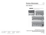
About the Switcher
The Extron ISM 182 and ISM 482 are eight-input, two-independently-scaled-output,
video and stereo audio matrix switchers. Figure 1-1 shows a typical ISM 482
application. The switchers accept high resolution RGB video, YUV (component)
video, S-video (Y/C), and composite video inputs; scale the inputs; and output
RGBHV or RGBS video and stereo audio. Triple-Action Switching™ (RGB delay)
blanks the screen during the switch to prevent distracting video glitches. The
switchers’ two independent scalers permit differing video formats on each input to
be displayed in different resolutions on different projectors.
Each video input is individually configurable to allow for different video formats.
The ISM allows analog RGBHV, RGBS, RGsB, and RGBcvS video, component
video, S-video, and composite video signals to be displayed on a device with a
fixed resolution and aspect ratio, such as a liquid crystal display (LCD) projector,
digital light processor (DLP) projector, or plasma display.
The ISM provides two separate outputs. The selected input can be switched to
either or both outputs.
The switchers input all valid video signal formats on eight sets of five BNC
connectors. The ISM 482 scales the input up or down to any of 40 output
resolutions and rates. The ISM 182 scales the inputs to any of 20 resolutions and
rates. Either switcher outputs the scaled video, as RGBHV or RGBS, on two sets of
output connectors, consisting of five BNCs and a 15-pin HD connector. The BNCs
and 15-pin HD connector share identical outputs. Several of the output resolutions
and rates include Extron’s Accu-RATE Frame Lock™ (AFL™), a proprietary
technology that locks the output frame rate to the input rate, solving the image
tearing problem that can result from different input and output rates. The ISM 482
features HDTV 576p, 720p, 1080p, and 1080i outputs.

1-3Integration Scaling Matrix Switcher • Introduction
Podium PC
Projector
Projector
Extron
ISM 482
Codec
RS-232
VCR
Laptop
1
2
3
4
5
6
7
8
1
0
0
-
2
4
0
5
0
/6
0
H
z
1
.
2
A
M
A
X
.
R
1
G
B
H
/H
V
R
2
G
B
H
/H
V
R
3
G
B
H
/H
V
R
I
N
P
U
T
S
4
G
B
H
/
H
V
R
5
G
B
H
/
H
V
R
6
G
B
H
/
H
V
R
7
G
B
H
/
H
V
R
8
G
B
H
/
H
V
R
1
O
U
T
P
U
T
S
1
2
R
S
-
2
3
2
D
V
I
O
U
T
G
B
H
/H
V
V
R
2
G
B
H
/H
V
V
ETHERNET
L
I
N
K
A
C
T
DVD Player
Extron
RGB 112xi
LAN/WAN
Network/
Internet
Figure 1-1— Typical ISM 482 Integration Scaling Matrix Switcher
application
The ISM receives and outputs the stereo audio on 5-pole captive screw connectors.
For upscaling, the ISM 482 converts the horizontal and vertical sync timing and the
number of lines of the lower-resolution video input to match the native resolution
of the display. This produces an undistorted, brighter picture than an unscaled
input would.
For downscaling, the ISM 482 accepts any computer resolution, up to 1600 x 1200,
with horizontal scan rates up to 100 kHz and vertical scan rates up to 120 Hz, and
converts the input to match the native resolution of the display.
The switchers are ideal for displaying images on projectors with limited display
resolutions, such as LCD projectors, DLP projectors, and plasma projectors.
The switchers feature built-in test patterns to aid in monitor or projector set-up and
evaluation.
The switchers are housed in a rack-mountable, 3U high, 17.5” wide, metal
enclosure. The ISM has an internal 100VAC to 240VAC, 50/60 Hz, 30 watts
autoswitchable power supply that provides worldwide power compatibility.

Introduction, cont’d
Integration Scaling Matrix Switcher • Introduction1-4
Features
Inputs —
Video inputs — The ISM switches among eight fully-configurable RGB, HDTV
component video (ISM 482), component video, S-video, and composite video
inputs on five BNC connectors per input.
Audio inputs — The ISM switches among eight balanced or unbalanced stereo or
mono audio inputs on 5-pole captive screw connectors.
Outputs —
Video outputs — The ISM outputs individually scaled video signals as RGBHV
or RGBS. Two sets of BNC connectors and two 15-pin HD connectors are
provided. One set of BNC connectors and one 15-pin HD connector display
the output 1 image, and the other set of BNC connectors and 15-pin HD
connector display the output 2 image.
Audio outputs — The ISM outputs the selected unamplified, line level, balanced
or unbalanced stereo or mono audio on 5-pole captive screw connectors.
Accu-RATE Frame Lock™ (AFL™) — A patented technology exclusive to Extron
that solves frame rate conversion issues experienced by video scalers. When
video input and output refresh rates differ, occasionally the two rates cross
over each other. The result is a glitch or image freeze on the display. AFL
solves this problem by locking the output frame rate to the input frame rate.
Dynamic Motion Interpolation™ (DMI™) — This video processing technique is
an advanced motion prediction and compensation method that treats motion
content and still content with different algorithms to yield high fidelity images.
3:2 pulldown detection for NTSC video sources and 2:2 film detection for PAL —
These advanced, patent pending, film mode processing feature helps
maximize image detail and sharpness for video sources that originated from
film. When film is converted to NTSC video, the film frame rate has to be
matched to the video frame rate in a process called 3:2 pulldown. Jaggies and
other image artifacts can result if conventional deinterlacing techniques are
used on film-source video. The ISM’s advanced film mode processing
recognizes signals that originated from film. The ISM then applies video
processing algorithms that optimize the conversion of video that was made
with the 3:2 pulldown process. This results in richly detailed images with
sharply defined lines.
A similar process is used for PAL film-source video.
Audio follow and breakaway — Audio switching can follow its corresponding
video input signal or it can be broken away from the video input. Audio
breakaway switching can be done via front panel control or under RS-232 or
Ethernet remote control.
Audio gain/attenuation — Users can set the input level of audio gain or
attenuation (-24dB to +9dB) via the RS-232 or Ethernet link or from the front
panel. Individual input audio levels can be adjusted so there is no noticeable
volume difference between sources.
Ethernet port — Supports connection to an Ethernet LAN so that the switcher can
be accessed and operated from a computer running a standard Internet
browser anywhere in the world.
Quad-standard video decoder — The switcher uses a digital, four-line adaptive
comb filter that can decode NTSC 3.58, NTSC 4.43, PAL, and SECAM.

1-5Integration Scaling Matrix Switcher • Introduction
Test patterns — The switcher features built-in test patterns to aid in monitor or
projector set-up and evaluation.
Blue mode — The switcher can be set to output the blue video signal only, to help
installers calibrate the monitor or projector.
Triple-Action Switching
™
(RGB delay) — RGB delay mutes the R, G, and B video
planes to blank the screen while the scaler locks to the new sync, so that a
noise-filled scramble is not shown on the monitor during the transition. The
time delay between the RGB and sync signals is user adjustable up to five
seconds under front panel, SIS, and program control.
Auto memories — The eight inputs support 16 auto-recall memories each, based on
the incoming frequency. Information on sizing, centering, detail, contrast,
and brightness is saved.
Auto Image
™
— The auto imaging feature automatically sizes and centers the
selected input to fill the screen. Auto imaging can be selected for individual
inputs as desired or set to automatically size and center each new input
selection.
Memory presets — The ISM 482 has memory for up to 128 presets that allow the
user to use RS-232 commands to save and recall color, tint, contrast,
brightness, centering, and sizing, and filtering information.
Aspect ratio memories — Three memories for each input save different color, tint,
contrast, brightness, detail, size, and centering settings.
Freeze mode (under SIS and Windows program control only) — Locks the output
display to the selected image. Once frozen, an input can be removed without
losing the output image. This feature lets the ISM store a still image.
Rack mounting — The 3U high switcher can be mounted in any conventional 19”
wide rack.

Introduction, cont’d
Integration Scaling Matrix Switcher • Introduction1-6

Integration Scaling Matrix Switcher
2
Chapter Two
Installation
Mounting the Switcher
Cabling and Rear Panel Views
Configuration

Installation, cont’d
Integration Scaling Matrix Switcher • Installation2-2
Installation
Mounting the Switcher
Four uninstalled rubber feet are included with the switcher . If you are going to
rack mount the switcher, mount it before you cable it (see Rack mounting, below),
and do not install the rubber feet. If you are not rack mounting the switcher, see
Tabletop placement below.
Tabletop placement
For tabletop placement, install the self-adhesive rubber feet/pads (provided) onto
the four corners of the bottom of the switcher.
Rack mounting
To rack mount the switcher, use two screws on each end of the switcher to attach
the switcher to the rack (see figure 2-1).
B
L
A
C
K
1
2
3
4
5
6
7
8
V
I
D
E
O
1
2
O
U
T
P
U
T
1
2
3
4
5
6
7
8
A
U
D
I
O
M
U
T
E
C
O
L
O
R
/
T
I
N
T
B
R
T
/
C
O
N
T
S
I
Z
E
C
E
N
T
E
R
F
I
L
T
E
R
A
D
J
U
S
T
M
E
N
U
N
E
X
T
INPUTS
IS
M
4
8
2
IN
T
E
G
R
A
T
IO
N
S
C
A
L
IN
G
M
A
T
R
IX
Figure 2-1 — Mounting the switcher

2-3Integration Scaling Matrix Switcher • Installation
Cabling and Rear Panel Views
All connectors are on the rear panel (figure 2-2).
100
-
240
50/60 Hz
1.2A MAX.
12
H/HV
V
3
H/HV
V
INPUTS
4
H/HV
V
5
H/HV
V
6
H/HV
V
7
H/HV
V
R/R-Y
8
G/Y
VID
B/C
B-Y
R/R-Y
G/Y
VID
B/C
B-Y
R/R-Y
G/Y
VID
B/C
B-Y
R/R-Y
G/Y
VID
B/C
B-Y
R/R-Y
G/Y
VID
B/C
B-Y
R/R-Y
G/Y
VID
B/C
B-Y
R/R-Y
G/Y
VID
B/C
B-Y
R/R-Y
G/Y
VID
B/C
B-Y
H/HV
V
1
OUTPUTS
1
2
RS-232
2
234 5678
H/HV
V
1
R
G
B
H/HV
V
R
G
B
H/HV
V
ETHERNET
LINK
AC
T
1 3 5 6
2 4
7
Figure 2-2 — ISM 482 rear panel connectors
Input connections
1
AC power connector — Plug a standard IEC power cord into this connector
to connect the switcher to a 100 to 240VAC, 50 Hz or 60 Hz power source.
2
Input video connectors — Connect computer or RGB video, component
video, S-video, or composite video to these female BNC connectors.
Figure 2-3 shows how to connect the various video formats.
H/HV
RGBHV
Video
RGsB or
Component
Video
S-Video Composite
Video
RGBS or
RGBcvS
Video
V
H/HV
V
H/HV
V
H/HV
V
H/HV
V
R/R-Y
G/Y
VID
B/C
B-Y
R/R-Y
G/Y
VID
B/C
B-Y
R/R-Y
G/Y
VID
B/C
B-Y
R/R-Y
G/Y
VID
B/C
B-Y
R/R-Y
G/Y
VID
B/C
B-Y
Figure 2-3 — Connections for various input video formats

Installation, cont’d
Integration Scaling Matrix Switcher • Installation2-4
3
Input audio connectors — Connect balanced or unbalanced stereo or mono
audio to these 3.5 mm, 5-pole captive screw connectors.
Connectors are included with the seamless switcher, but
you must supply the audio cable. Figure 2-4 shows how to
wire a connector for the appropriate input type and
impedance level. High impedance is generally over 800
ohms.
Unbalanced Input
Tip
Sleeve
Tip
Sleeve
Balanced Input
Tip
Ring
Sleeve (s)
Tip
Ring
Tip
Ring
Sleeve (s)
Tip
Ring
Balanced Input
(high impedance)
(high impedance) (600 ohms)
600 ohms
600 ohms
Figure 2-4 — Captive screw connector wiring for inputs
When making connections for the seamless switcher from existing audio cables,
see figure 2-5. A mono audio connector consists of the tip and sleeve. A stereo
audio connector consists of the tip, ring and sleeve. The ring, tip, and sleeve
wires are also shown on the captive screw audio connector diagram, figure 2-4.
Tip (+)
Sleeve ( )
Sleeve ( )
Ring (
-
)
Tip (+)
RCA Connector
3.5 mm Stereo Plug Connector
(balanced)
Figure 2-5 — Phono audio connectors
The audio level for each input can be individually set, via the front panel, the
Ethernet link, or the RS-232 link, to ensure that the level on the output does
not vary from input to input. See chapter 3, Operation, chapter 4, Programmer’s
Guide, chapter 5, Switcher Software, and chapter 6, Ethernet Operation for
details.

2-5Integration Scaling Matrix Switcher • Installation
Output connections
The two Output 1 outputs, consisting of five BNC connectors and a 15-pin
HD connector, output the identical video signal and the same sync format.
The two Output 2 outputs are also identical to each other.
4
Video output BNC connectors— Connect RGB video displays to these two
sets of female BNC connectors. Figure 2-6 shows how to connect the various
video formats.
H/HV
R
G
B
H/HV
RGBHV
Video
RGBS
Video
V
R
G
B
V
Figure 2-6 — BNC output connections for RGBHV and RGBS video
Video output 15-pin HD connectors — Connect RGB video
displays to these two female 15-pin HD connectors.
5
Audio output connectors — Connect audio devices, such as an audio
amplifier or powered speakers to these two 3.5 mm, 5-pole captive screw
connectors. The connectors output the selected unamplified, line level audio.
See figure 2-7 to properly wire an output connector.
Unbalanced Output
Tip
See caution
Sleeve
Tip
See caution
Balanced Output
Tip
Ring
Sleeve (s)
Tip
Ring
Figure 2-7 — Captive screw connector wiring for audio output
CAUTION
Connect the sleeve to ground (Gnd). Connecting the sleeve to a
negative (-) terminal will damage the audio output circuits.
By default, the audio output follows the video switch. Audio breakaway,
commanded via the front panel, the Ethernet link, or the RS-232 link, allows
you to select from any one of the audio input sources. See chapter 3,
Operation, chapter 4, Programmer’s Guide, chapter 5, Switcher Software, and
chapter 6, Ethernet Operation for details.

Installation, cont’d
Integration Scaling Matrix Switcher • Installation2-6
Ethernet connection
6
Ethernet port — If desired connect the switcher to an Ethernet LAN or WAN
via this RJ-45 connector. Ethernet control allows the operator to control the
switcher from a remote location. When connected to an Ethernet LAN or
WAN , the switcher can be accessed and operated from a computer running a
standard Internet browser.
Ethernet connection indicators — The Link and Act LEDs indicate the status
of the Ethernet connection.
The Link LED indicates that the switcher is properly connected to an
Ethernet LAN. This LED should light steadily.
The Act LED indicates transmission of data packets on the RJ-45
connector. This LED should flicker as the switcher communicates.
Cabling and RJ-45 connector wiring
It is vital that your Ethernet cables be the correct cables, and that they be properly
terminated with the correct pinout.
Choosing a network cable
Ethernet links use Category (CAT) 3, 4, 5, 5e, or 6, unshielded twisted pair (UTP) or
shielded twisted pair (STP) cables, terminated with RJ-45 connectors. Ethernet
cables are limited to 328’ (100 m).
Do not use standard telephone cables. Telephone cables will not support
Ethernet or Fast Ethernet.
Do not stretch or bend cables. Transmission errors can occur.
The cable used depends on your network speed. The ISM supports both 10 Mbps
(10Base-T — Ethernet) and 100 Mbps (100Base-T — Fast Ethernet), half-duplex and
full-duplex, Ethernet connections.
• 10Base-T Ethernet requires, at a minimum, CAT 3 UTP or STP cable.
• 100Base-T Fast Ethernet requires, at a minimum, CAT 5 UTP or STP cable.
LINK
ACT
/