Page is loading ...

1
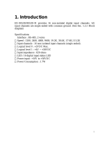
1. Introduction
EX9066D/9066D-M series provides 7 PhotoMOS Relay output channels. all
output channels are differential with individually common . (see sec. 1.2.1
Block diagram). For High-speed inspection machines/Telephone
equipment/ Data communication equipment Application.
Specifications
Interface : RS-485, 2 wires
Speed : 1200, 2400, 4800, 9600, 19.2K, 38.4K, 57.6K,115.2K
Output channels: 7 PhotoMOS output channels with Normal Open (Form A)
Load Current: 0.13A
Load Voltage: 350V Max
Isolation Voltage: 5000VDC
Operate Time: 0.7mS typ
Release Time: 0.05mS typ
Power Input: +10V to +30VDC.
LED: 7 output status LED
Power input : +10V to +30VDC
Power Consumption : 1.9W
EX9067D/9067D-M series provides 7 relay output channels. all relay output
channels are differential with individually common . (see sec. 1.2.1 Block
diagram)
Specifications
Interface : RS-485, 2 wires
Speed : 1200, 2400, 4800, 9600, 19.2K, 38.4K, 57.6K,115.2K
Output channels: 7 relay output channels with Normal Open (Form A)
Relay contact rating : 0.5A/120Vac, 1.0A/24Vdc
Surge strength: 1500V
Operate Time: 5mS max.
Release Time: 2mS max.
Min Life: 105 ops.
LED: 7 output status LED
Power input : +10V to +30VDC
Power Consumption : 1.9W

2
1.1 Specifications
EX9066D EX9067D
Digital Output 7 PhotoMOS Output 7 Relay Output
Output Channels Form A
Relay Type Load Current: 0.13A
Load Voltage: 350V Max
Isolation Voltage: 5000VDC
Operate Time: 0.7mS typ
Release Time: 0.05mS typ
Power Input: +10V to +30VDC
Contact Rating:
0.5A@120VAC
1.0A@24VDC
Surge Strength: 1500V
Operate Time: 5mS Max
Release Time: 2mS Max
Min. Life: 105ops
Environment
Power Requirement +10 to +30 VDC
Power Consumption 1.9W
Operating Temperature -25°C to +75°C
Storage Temperature -30°C to +75°C

3
1.2 Wire connection
1.2.1 Block Diagrams
Led
Display
EEPROM
Single
Controller
RS485
Interface
Power
Supply
+5V
+5V
RL6NO
EX9066D
Data+
Data-
+Vs
GND
RL1COM
RL1NO
RL6COM
RL7COM
RL7NO
Led
Display
EEPROM
Single
Controller
RS485
Interface
Power
Supply
+5V
+5V
RL6NO
EX9067D
Data+
Data-
+Vs
GND
RL1COM
RL1NO
RL6COM
RL7COM
RL7NO

4
1.2.2 Wiring diagram for the EX9066D/67D
Relay output
1.3 Default Settings
Default settings for the EX9066D/9067D
modules are as follows:
. Module Address: 01
. DIO Type: 40
. Baud Rate: 9600 bps
. Protocol: ASCII command.
Default settings for the EX9066D-M/9067D-M
modules are as follows:
. Module Address: 01
. DIO Type: 40
. Baud Rate: 9600 bps
. Protocol: Modbus RTU

5
1.4 INIT* Mode Operation
Each EX9000 module has a build-in EEPROM to store
configuration information such as address, type, baudrate and other
information. Sometimes, user may forget the configuration of the
module. Therefore, the EX9000 have a special mode named "INIT*
mode" to help user to resolve the problem. The "INIT* mode" is
setting as Address=00, Baudrate=9600bps, no Checksum .
Originally, the INIT* mode is accessed by connecting the INIT*
terminal to the GND terminal. New EX9000 modules have the
INIT* switch located on the rear side of the module to allow easier
access to the INIT* mode. For these modules, INIT* mode is
accessed by sliding the INIT* switch to the Init position as shown
below.
To enable INIT* mode, please following these steps:
Step1. Power off the module
Step2. Connect the INIT* pin with the GND pin.
(or sliding the INIT* switch to the Init* ON position)
Step3. Power on
Step4. Send command $002 (cr) in 9600bps to read the
Configuration stored in the module's EEPROM.
There are commands that require the module to be in INIT* mode.
They are:
1. %AANNTTCCFF when changing the Baud Rate and checksum
settings. See Section 2.1 for details.
2. $AAPN, See Section 2.14 for details.

6
1.5 Module Status for DIO, AIO
Power On Reset or Module Watchdog Reset will let all
output goto Power On Value. And the module may accept the
host's command to change the output value.
Host Watchdog Timeout will let all output goto Safe Value.
The module's status(readed by command~AA0) will be 04, and the
output command will be ignored.
1.6
Dual Watchdog Operation for DIO, AIO
Dual Watchdog=Module Watchdog + Host Watchdog
The Module Watchdog is a hardware reset circuit to monitor
the module's operating status. While working in harsh or noisy
environment, the module may be down by the external signal. The
circuit may let the module to work continues and never halt.
The Host Watchdog is a software function to monitor the
host's operating status. Its purpose is to prevent the network from
communication problem or host halt. When the timeout interval
expired, the module will turn all outputs to predefined Safe Value.
This can prevent the controlled target from unexpected situation.
The EX9000 module with Dual Watchdog may let the
control system more reliable and stable.
1.7 Reset Status
The Reset Status is set while the module power on or reset by
module watchdog and is cleared while the command read Reset
Status ($AA5) applied. This is useful for user to check the module's
working status. When the Reset Status is set means the module is
reset and the output may be changed to the PowerOn Value. When
the Reset Status is clear means the module is not rested and the
output is not changed.

7
1.8 Digital O/P
The module's output have 3 different situtation:
<1>Safe Value. If the host watchdog timeout status is set,
the output is set to Safe Value. While the module receive the output
command like @AA(Date) or #AABBDD, the module will ignore
the command and return "!". And will not change the output to the
output command value. The host watchdog timeout status is set
and store into EEPROM while the host watchdog timeout
interval expired and only can be cleared by command ~AA1. If
user want to change the output it need to clear the host watchdog
timeout status firstly and send output command to change the output
into desired value.
<2>PowerOn Value. Only the module reseted and the host
watchdog timeout status is clear, the module's output is set to
predefined Power On Value.
<3> Output Command Value. If the host watchdog timeout
status is clear and user issue a digital output command like @AA
(Data) or #AABBDD to module for changing the output value. The
module will reponse success (receive>).
1.9 Latch Digital I/P
For example, use connect the key switch to Digital input channel of
a digital input/output module and want to read the key stoke. The
Key input is a pulse digital input and user will lost the strike. While
reading by command $AA6 in A and B position, the response is that
no key stroke and it will lose the key stroke information. Respectly,
the read latch low digital input command $AAL0 will solve this
problem. When issue $AAL0 command in A and B position, the
response denote that there is a low pulse between A and B position
for a key stroke.

8
1.10 Configuration Tables
Baud Rate Setting (CC)
Code 03 04 05 06 07 08 09 0A
Baud rate 1200 2400 4800 9600 19200 38400 57600 115200
Data Format Setting (FF)
7 6 5 4 3 2 1 0
*1 *2 *3
*1: Counter Update Direction: 0 =Falling Edge,
1=Rising Edge.
*2: Checksum Bit : 0=Disable, 1=Enable.
*3: The reserved bits should be zero.
Read Digital Input/Output Data Format table
Data of $AA6,$AA4,$AALS:(First Data)(Second Data)00
Data of @AA:(First Data)(Second Data)
Note: Both the First Data and the Second Data are in two
hexadecimal digitals format.
Module The First data The Second data
EX9066D/67D DO1~DO7 00~7F 00

9
2.0 Command Sets
2.1 %AANNTTCCFF
Description: Set Module Configuration.
Syntax: %AANNTTCCFF[CHK](cr)
% a delimiter character
AA address of setting/response module(00 to FF)
NN new address for setting/response module(00 to FF)
TT type 40 for DIO module
CC new baudrate for setting module.
FF new data format for setting module.
If the configuration with new baudrate or new checksum
setting, before using this command, it is needed to short the
INIT* to ground (or sliding the INIT* switch to the Init ON
position of rear side). The new setting is saved in the
EEPROM and will be effective after the next power-on reset.
Response: Valid Command: !AA
Invalid Command: ?AA
Example:
Command: %0102240600 Receive: !02
Set module address 01 to 02, return Success.

10
2.2 #**
Description: Synchronized Sampling
Syntax: #**[CHK](cr)
# delimiter character
** synchronized sampling command
Response: No response
Example:
Command: #** No response
Send synchronized sampling command to all modules.
Command: $014 Receive: !10F0000
Read synchronized data from address 01, return S=1, first read
and data is 0F0000
Command: $014 Receive: !00F0000
Read synchronized data from address 01, return S=0, have readed
and data is 0F0000

11
2.3 #AABBDD
Description: Digital Output
Syntax: #AABBDD[CHK](cr)
# delimiter character
AA address of reading/response module(00 to FF)
BBDD Output command and parameter
For output multi-channel, the BB=00, 0A or 0B the
select which output group, and the DD is the output
value
Parameter for Multi-Channel Output
DD for command #AABBDD Output
Channels BB=00/0A BB=0B
EX9042D 13 00 to FF DO(0~7) 00 to 1F DO(8~12)
EX9043D 16 00 to FF DO(0~7) 00 to 1F DO(8~15)
EX9044D 8 00 to FF DO(0~7) NA NA
EX9050D 8 00 to FF DO(0~7) NA NA
EX9055D 8 00 to FF DO(0~7) NA NA
EX9060D 4 00 to 0F RL(1~4) NA NA
EX9063D 3 00 to 07 RL(1~3) NA NA
EX9065D 5 00 to 1F RL(1~5) NA NA
EX9066D 7 00 to 7F RL(1~7) NA NA
EX9067D 7 00 to 7F RL(1~7) NA NA
EX9068D-M 8 00 to FF RL(1~8) NA NA

12
For output single-channel, the BB=1c, Ac or Bc where c is
the selected channel, and the DD must be 00 to clear output
and 01 to set output.
Parameter for Single-Channel Output
Single channel output command #AABBDD
c for BB=1c/Ac c for BB=Bc
EX9042D 0 to 7 DO(0~7) 0 to 4 DO(8~12)
EX9043D 0 to 7 DO(0~7) 0 to 7 DO(8~15)
EX9044D 0 to 7 DO(0~7) NA NA
EX9050D 0 to 7 DO(0~7) NA NA
EX9055D 0 to 7 DO(0~7) NA NA
EX9060D 0 to 3 RL(1~4) NA NA
EX9063D 0 to 2 RL(1~3) NA NA
EX9065D 0 to 4 RL(1~5) NA NA
EX9066D 0 to 6 RL(1~7) NA NA
EX9067D 0 to 6 RL(1~7) NA NA
EX9068D-M 0 to 7 RL(1~8) NA NA
Response: Valid Command: >
Invalid Command: ?
Ignore Command: !
Delimiter for ignore the command. The module's
host watchdog timeout status is set, and the output
is set to Safe Value.

13
Example:
Command: #021001 Receive: >
Assume module is EX9067D-M, set address 02 output channel 0
on, return success.
Command: #021001 Receive: >
Assume module is EX9067D-M, set address 02 output channel 0
on, return ignore, The module’s host watchdog timeout status is
set, and the output is set to Safe Value.

14
2.4 $AA2
Description: Read configuration.
Syntax: $AA2[CHK](cr)
$ delimiter character
AA address of reading/response module (00 to FF)
2 command for read configuration
Response: Valid Command: !AATTCCFF
Invalid Command: ?AA
TT type code of module, it must be 40
CC baudrate code of module
FF data format of module
Example:
Command: $012 Receive: !01400600
Read the configuration of module 01, return DIO mode,
b
audrate
9600, no checksum.
Note: check configuration Tables

15
2.5 $AA4
Description: Reads the synchronized data
Syntax: $AA4[CHK](cr)
$ delimiter character
AA address of reading/response module (00 to FF)
4 command to read the synchronized data
Response: Valid Command: !S(Data)
Invalid Command: ?AA
S status of synchronized data, 1=first read, 0=been readed
(Data) synchronized DIO value. See section 1.5 for data format.
Example:
Command: $014 Receive: ?01
Read address 01 synchronized data, return no data available.
Command: #** no response
Send synchronized sampling to all modules.
Command: $014 Receive: !1070000
Read address 01 synchronized data, return S=1, first read, and
synchronized data 0700

16
2.6 $AA5
Description: Read Reset Status
Syntax: $AA5[CHK](cr)
$ delimiter character
AA address of reading/response module (00 to FF)
5 command for read reset status
Response: Valid Command: !AAS
Invalid Command: ?AA
S reset status, 1=the module is been reset, 0=the module is
not been rested
Example:
Command: $ 015 Receive: !011
Read address 01 reset status, return module is been reset
Command: $ 015 Receive: !010
Read address 01 reset status, return no reset occurred.

17
2.7 $AA6
Description: Read Digital I/O Status
Syntax: $AA6[CHK](cr)
$ delimiter character
AA address of reading/response module (00 to FF)
6 command for read channel status
Response: Valid Command: !(Data)
Invalid Command: ?AA
(Data) (First Data)(Second Data)00
Note: Both the First Data and the Second Data are in two
hexadecimal digitals format.
Module The First data The Second data
EX9066D/67D DO1~DO7 00~7F 00
Example:
Command: $016 Receive: !0F0000
Assume module is EX9067D-M, read address 01 DIO status,
return 0F00, digital output channel 1~4 are on.

18
2.8 $AAF
Description: Read Firmware Version
Syntax: $AAF[CHK](cr)
$ delimiter character
AA address of reading/response module (00 to FF)
F command for read firmware version
Response: Valid Command: !AA(Data)
Invalid Command: ?AA
(Data) Firmware version of module
Example:
Command: $01F Receive: !01D03.11
Read address 01 firmware version, return version D03.11

19
2.9 $AAM
Description: Read Module Name
Syntax: $AAM[CHK](cr)
$ delimiter character
AA address of reading/response module (00 to FF)
M address of reading/response module(00 to FF)
Response: Valid Command: !AA(Data)
Invalid Command: ?AA
(Data) Name of module
Example:
Command: $01M Receive: !019067
Read address 01 module name, return name 9067

20
2.10 @AA
Description: Read Digital I/O Status
Syntax: @AA[CHK](cr)
@ delimiter character
AA address of reading/response module (00 to FF)
Response: Valid Command: >(Data)
Invalid Command: ?AA
(Data) (First Data)(Second Data)
Note: Both the First Data and the Second Data are in two
hexadecimal digitals format.
Module The First data The Second data
EX9066D/67D DO1~DO7 00~7F 00
Example:
Command: @01 Receive: >0F00
Assume module is EX9067D-M, read address 01 DIO status,
return 0F00, digital output channel 1~4 are on.
/