Page is loading ...

Werner Fall Protection 724-588-2000
93 Werner Rd. 888-523-3371 toll free/ llamada gratuita
Greenville, PA 16125 888-456-8458 fax
(This manual applies to all self-retracting lifelines with model
numbers starting R2.)
(Este manual aplica a todas las cuerdas salvavidas auto-retráctiles
con números de modelo que comienzan en R2).
SELF-RETRACTING LIFELINE
Complies with ANSI Z359.1-2007,
OSHA 1910 and 1926 requirements.
CUERDA SALVAVIDAS
AUTO-RETRÁCTIL
Cumple con las normas ANSI Z359,
1-2007, OSHA 1910 y 1926.
FALL PROTECTION
USER INSTRUCTIONS
PROTECCIÓN CONTRA CAÍDAS
INSTRUCCIONES PARA EL USUARIO
STITCHING
TORN
CUERDA SALVAVIDAS AUTO-RETRÁCTIL

Page 2
ENGLISH
Contents
I. BEFORE USING SELF-RETRACTING LIFELINE .............................................4
a. Inspect ......................................................................................................................4
b. Compatibility ............................................................................................................6
c. Clearance ..................................................................................................................6
d. Rescue Plan .............................................................................................................7
e. Training .....................................................................................................................7
II. SELF-RETRACTING LIFELINES INSTALLATION AND USE .......................... 7
a. Choose Adequate Anchorage .................................................................................7
1. Verify Strength .......................................................................................................7
2. Only One Worker ..................................................................................................7
b. Cable Slack ..............................................................................................................7
c. Rewinding Device ................................................................................................... 7
d. Spring Tension .........................................................................................................7
e. Maintenance ............................................................................................................ 8
f. Repair Service .......................................................................................................... 8
g. Securing Single Leg Models ...................................................................................8
1. Secure SRL to Anchorage ................................................................................... 8
2. Secure SRL to Harness ........................................................................................8
h. Securing Dual Leg Models ......................................................................................9
1. Securing SRL to Harness .....................................................................................9
2. Securing to Anchorage and Use .........................................................................9
CAUTION!
If use of fall protection equipment is necessary, then the work
environment is dangerous and potentially deadly. Werner Co.
products are designed to eliminate as much of the hazard as possible,
but can do that ONLY if they are used correctly. Use this equipment as
it was designed to be used, after appropriate training, under the direct
supervision of a competent person, according to the instructions
provided, and in accordance with OSHA and local safety regulations.
User MUST read and understand all cautions and instructions. Failure
to heed these guidelines could result in injury or even death. WORK
SAFE! WORK SMART!

SELF-RETRACTING LIFELINES
USER INSTRUCTIONS
Page 3
ENGLISH
III. USE WARNINGS, RESTRICTIONS AND CAUTIONS ................................... 10
a. Adequate anchorages ........................................................................................... 10
b. Fall Distance .......................................................................................................... 10
c. Swing Fall Hazard ..................................................................................................11
d. Rated Capacity ....................................................................................................... 11
e. Environmental Hazards .........................................................................................11
f. Components/Subsystems ......................................................................................12
IV. LABELS/IDENTIFICATION/INSPECTION RECORDS .................................. 12
V. EQUIPMENT RECORDS ................................................................................ 19
VI. INSPECTION RECORDS .............................................................................. 19

Page 4
ENGLISH
Warning:
This product is just one part of a personal fall arrest system. It must
be matched correctly with other components to form a complete and
functional system. The user must understand the function of each of
these components and follow the manufacturer’s instructions for use
for each. The user must be provided these instructions, should read
and follow them, and consult the competent person who will supervise
his work if he has any questions about any part of the instructions.
The employer must provide training in the proper use, inspection, and
maintenance of all components in the system, and these instructions
can be used as part of that training. The equipment should be used
ONLY in accordance with these instructions, local ordinances and
codes, the applicable OSHA and ANSI standards, and the employer’s
safety plan.
This Self-Retracting Lifeline (SRL) system is designed to provide
a variable length energy absorbing connection from an approved
anchorage to the dorsal (back) D-ring of an approved fall protection
harness. Use of an SRL is appropriate for doing work that requires
movement, especially when changing levels.
IF YOU HAVE ANY QUESTIONS ABOUT ANYTHING IN THESE
INSTRUCTIONS, THE EQUIPMENT, OR PROPER USE OF THE
EQUIPMENT, CONTACT WERNER CO. FOR MORE INFORMATION.
I. Before Using the Self-Retracting Lifeline
Before using this equipment the user should take certain steps to
ensure that it is in suitable condition and safe for use. Users must
read and understand these instructions. It is the employer’s obligation
to ensure that all users have been trained in safe work procedures
as well as in the use and limitations of fall protection equipment. All
users should be aware of and comply with all applicable OSHA, ANSI
and local or regional regulations concerning fall protection equipment
and its use.
a. Inspect
Examine all equipment thoroughly, daily before use by the user,
and periodically by a competent person who is not the user.

SELF-RETRACTING LIFELINES
USER INSTRUCTIONS
Page 5
ENGLISH
Verify the condition of each component. If any damage or
abnormalities are found, the equipment should be removed from
service. No modications to the equipment are permitted. Verify
that all components are present, intact and undamaged, and
functioning correctly.
1. Inspect the housing for any dents, cracks, loose fasteners, or
any other condition that could affect the safe use and operation
of the unit.
2. Open and close the snap hook several times to ensure the
mechanisms are working smoothly, correctly, and the snap
hook’s gate closes completely.
3. Put on leather gloves for protection and pull the cable, rope or
web completely from the SRL while sliding it through the gloved
hand. Carefully examine every inch as it retracts, looking for
cuts, abrasions, chemical damage, corrosion, kinks, or any
other damage that could weaken it. Check the ferrules for
cracking, corrosion, or any indication of movement. If any
damage is found, the device should be immediately removed
from service for repair.
4. Once the device is mounted
into its working position but
before connecting to it, pull
the cable out to verify the
line has adequate tension
and exits and retracts
smoothly. Test the brake
mechanism by giving the
cable several sharp tugs
to engage the pawls. The
device should lock each
time with no slipping.
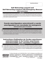
5. Check the load indicator
for signs of activation. On
models with a web lifeline
this is a stitch pattern
near the hook (see gure
1). On all other models
the snaphook contains a
red impact indicator (see
gure 2).If the device has
STITCHING
TORN
gure 1

Page 6
ENGLISH
suffered impact loading from a
fall, the snap hook’s red impact
indicator will be visible and
products should be removed from
service.
6. Verify that all labels are intact, in
place, and legible. If abnormalities
are found in any of these areas
then the competent person should
be consulted to determine if that
item is safe for continued use or if
it should be removed from service.
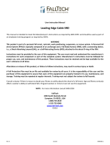
b. Compatibility
Verify compatibility of any subsystems being used. Werner Co.
products connected to Werner Co. products should be compatible.
Connection to other products must be veried for compatibility to
ensure there is no accidental detachment from side-loading, rollout,
non-standard closures, etc.
c. Clearance
Verify that adequate clearance exists below the work area and
there are no objects or obstructions below the work area that the
user could contact in the case of a fall.
INAPPROPRIATE CONNECTIONS
A. B. C.
D. E. F.
NO! NO! NO! NO!
NO!NO!NO!NO!
RED
LOAD
INDICATOR
gure 2

SELF-RETRACTING LIFELINES
USER INSTRUCTIONS
Page 7
ENGLISH
d. Rescue plan
If a worker falls and is forced to remain suspended for any length
of time, physical damage to the body or even death can result. For
this reason Werner Co., OSHA, ANSI and most local regulations
require that a rescue plan and the means to implement the rescue
plan are in place before use of this equipment.
e. Training
OSHA, ANSI, and most local ordinances require that workers using
this product receive adequate training before use of this product.
These instructions and their entire contents should be a part of that
training.
II. Self-Retracting Lifeline Installation and Use
a. Choose adequate anchorage
1. Verify strength of the anchorage chosen, which must be 5000
lbs (22.2kN), or twice the maximum expected impact load, as
certied by a qualied person.
2. Only one worker should be connected to any one anchorage
point.
b. Cable slack
Never permit the cable of a retractable lifeline to become slack. If
the cable is not properly retracting into the unit it must be removed
from service for inspection/repair.
c. Rewinding device
Cable should always be permitted to rewind into the device slowly
in a controlled manner. NEVER release the extended cable so
the cable rewinds unrestrained. To do so could damage the return
mechanism.
d. Spring tension
Never leave the cable in an extended position for a prolonged period
of time. To do so could affect the return spring tension. Use of a tag
line for devices mounted permanently overhead will eliminate any
need to leave the cable extended.

Page 8
ENGLISH
e. Maintenance
1. Periodically clean the housing exterior and lifeline with water
and a mild detergent. Rinse and towel and air dry.
2. Store in a clean, dry environment when not in use.
3. No alteration or modication of the device is permitted. Do
not attempt to open the device. It contains no user-serviceable
parts. If opened or modied the device should be removed
from service and returned to Werner Co. for inspection.
f. Repair Service
Any service or repair, such as lifeline replacement, must be
completed by an authorized service center. An authorization and
return number must be issued by Werner Co. Please contact
Werner Co. directly for more information about service and repairs.
g. Securing Single Leg Models
1. Secure SRL to anchorage
i. Connect body of retractable unit to the anchorage or
anchorage connector using the carabiner supplied or other
compatible hardware. Do not use a connector that will not
close completely when attached to anchor or anchorage
connector.
ii. The carabiner supplied with this unit comes with a roll pin,
that when installed provides a captive eye for connection
to the self retracting lifeline. Installation of the roll pin is
optional. To install the roll pin, drive the pin into the pre-
drilled hole in the back bar of the carabiner using a punch.
The open side of the roll pin should be facing away from
the lanyard or lifeline material. Continue driving the pin
through the back bar and into the front bar until the pin is
ush on the outside of the back bar.
iii. To connect the carabiner to the connection point, rotate
the gate clockwise and push to the center of the carabiner.
When positioned around a connection point, release the
gate to close and lock.
2. Secure SRL to harness
i. Connect SRL cable/web/rope snap hook only to the dorsal
(back) D-ring on the user’s harness.

SELF-RETRACTING LIFELINES
USER INSTRUCTIONS
Page 9
ENGLISH
h. Securing Dual Leg Models
1. Securing SRL to Harness
i. Connect body of retractable unit to the rear D-ring on the
harness using the carabiner supplied or other compatible
hardware.
ii. The carabiner supplied with this unit comes with a roll pin,
that when installed provides a captive eye for connection
to the self retracting lifeline. Installation of the roll pin is
optional. To install the roll pin, drive the pin into the pre-
drilled hole in the back bar of the carabiner using a punch.
The open side of the roll pin should be facing away from
the lanyard or lifeline
material. Continue
driving the pin through
the back bar and into
the front bar until the
pin is ush on the
outside of the back
bar.
iii. To connect the
carabiner to the
harness, rotate the
gate clockwise and
push to the center of
the carabiner. When
positioned around a connection point, release the gate to
close and lock. The SRL should be attached to the back
D-ring.
2. Securing to anchorage and use
i. Connect one of the free ends to
an anchor or anchor connector
ensuring that the connection is
compatible. With one SRL leg still
attached, the user can move to a
new location to attach the second
SRL leg to a different anchor and
then disconnect the rst leg
UNLOCKEDLOCKED TWIST

Page 10
ENGLISH
ii. When not in use the SRL leg
should be “parked” on the
wearer’s chest lanyard keeper,
never to a permanently xed
component on the harness (hip
D-ring, chest D-ring, etc.).
III. Use Warnings, Restrictions and Cautions
a. Adequate anchorages
OSHA requires anchor strengths of 5000 lbs (22.2 kN), or twice the
maximum expected load, as certied by a qualied person. Use of
any anchorage that is of inadequate strength could result in injury
or death.
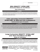
b. Fall Distance
Contact with a lower level can occur even when this equipment is
in perfect operating condition if there is any object in the path of
the fall or if the height of the anchorage being used is inadequate.
The fall distance can vary according to the connecting subsystem
used. The following diagram indicates typical clearance calculations
for self-retracting lifelines. While this depicts a typical situation the
authorized/competent person on site should make this determination
for each work situation depending on the site-specic conditions.

SELF-RETRACTING LIFELINES
USER INSTRUCTIONS
Page 11
ENGLISH
c. Swing Fall Hazard
Position the worker below
the anchorage so if a fall
occurs the worker will not
swing into an object below
the work surface.
d. Rated capacity
Rated for use by a maximum of 310 lbs (141kg) for the combined
weight of a worker and all tools when part of a complete fall
protection system. DO NOT EXCEED THIS WEIGHT.
e. Environmental hazards
This equipment is to be used only under the direct supervision of
a competent person who is able to identify hazards that must be
avoided, including electricity and chemicals, machinery or other
moving objects, sharp edges, damaged anchorages or structures,
or any other workplace element that could damage this equipment
or prevent it from operating as intended.
Full Body Harness
Connecting
Anchorage Connector
Anchorage
FALL ARREST
Full Body Harness
Full Arrest System
Anchorage Connector
Anchorage
Connector
Restraint
Lanyard
Anchorage
Anchorage
WORK POSITION
Full Body Harness
Cable
Cable Sleeve
Ladder
CLIMBING
SWING FALL
HAZARD
Anchorages
Correc
tI
ncorrect
Full Body Harness
Seat Board
Full Arrest System
Anchorage Connector Anchorage
Connector
Suspension Line
AnchorageAnchorage
PERSONNEL RIDING
Full Body Harness
Restraint Lanyard
Anchorage Connector
Anchorage
RESTRAINT
Working Level
Lower Level or Obstruction
Self Retracting
Lifeline Bottom of Retractable Lifeline
2 ft.
Maximum Free Fall Maximum Arrest
Distance (per ANSI)
4.5 ft.
See table 1 for free fall
distances per unit
2.5 ft.
Maximum Deceleration
2 ft.
Safety Factor
1 ft. Harness Stretch
5 ft.
To Worker’s Back D-Ring
Total Estimated
Fall Distance
12.5 ft.
Total Fall
Distance
(Free Fall +
Deceleration)
Free Fall
Working Level
Lower Level or Obstruction
Energy
Absorbing
LanyardLength of Anchorage Connector
6 ft.
Length of Lanyard
11 ft.
4 ft.
Deceleration Free Fall Distance
2 ft.
Safety Factor
1 ft. Harness Stretch
5 ft.
To Worker’s Back D-Ring
Total Estimated
Fall Distance
18 ft.
Full Body Harness
Connecting
Anchorage Connector
Anchorage
FALL ARREST
Full Body Harness
Full Arrest System
Anchorage Connector
Anchorage
Connector
Restraint
Lanyard
Anchorage
Anchorage
WORK POSITION
Full Body Harness
Cable
Cable Sleeve
Ladder
CLIMBING
SWING FALL
HAZARD
Anchorages
CorrectIncorrect
Full Body Harness
Seat Board
Full Arrest System
Anchorage Connector Anchorage
Connector
Suspension Lin
e
AnchorageAnchorage
PERSONNEL RIDING
Full Body Harness
Restraint Lanyard
Anchorage Connector
Anchorage
RESTRAINT
Working Level
Lower Level or Obstruction
Self Retracting
Lifeline Bottom of Retractable Lifeline
2 ft.
Maximum Free Fall Maximum Arrest
Distance (per ANSI)
4.5 ft.
See table 1 for free fall
distances per unit
2.5 ft.
Maximum Deceleration
2 ft.
Safety Factor
1 ft. Harness Stretch
5 ft.
To Worker’s Back D-Ring
Total Estimated
Fall Distance
12.5 ft.
Total Fall
Distance
(Free Fall +
Deceleration)
Free Fall
Working Level
Lower Level or Obstruction
Energy
Absorbing
LanyardLength of Anchorage Connector
6 ft.
Length of Lanyard
11 ft.
4 ft.
Deceleration Free Fall Distance
2 ft.
Safety Factor
1 ft. Harness Stretch
5 ft.
To Worker’s Back D-Ring
Total Estimated
Fall Distance
18 ft.
Fall distance for self-retracting lifeline

Page 12
ENGLISH
f. Components / Subsystems
Before rst use, a qualied person should inspect all components
and ensure subsystems are compatible and will perform correctly
when combined into a complete personal fall protection system.
Consult the information in these instructions, and if any additional
information is needed, contact Werner Co. directly.
IV. Labels/Identication/Inspection Records
a. All products should be inspected by the user thoroughly before
each use. Additional inspections by a competent person other than
the user should be conducted at least annually. That interval should
be shortened any time the product is used in a harsh environment
or is exposed to conditions such as chemicals, abrasion, heat or
any other factor that could affect the strength of any of the materials
or components.
b. The product labels provide an inspection grid to record these
inspections by a competent person. Use a permanent marker to
record those dates.
c. This manual should always accompany the product or be on le with
the employer for access when needed. Record the identication
details for the anchor and record the inspections in the inspection
record on page 17. It is important to maintain this log with current,
complete information and have it available as needed.

SELF-RETRACTING LIFELINES
USER INSTRUCTIONS
Page 13
ENGLISH
Labels
front and back

Page 14
ENGLISH

SELF-RETRACTING LIFELINES
USER INSTRUCTIONS
Page 15
ENGLISH

Page 16
ENGLISH

SELF-RETRACTING LIFELINES
USER INSTRUCTIONS
Page 17
ENGLISH

Page 18
ENGLISH

SELF-RETRACTING LIFELINES
USER INSTRUCTIONS
Page 19
ENGLISH
SPECIFICATIONS
PART NUMBER
SERIAL NUMBER
DATE
MANUFACTURED
PURCHASE DATE
ASSIGNED TO
DATE INSPECTOR PASS/FAIL DATE INSPECTOR PASS/FAIL
Werner Co. Self-Retracting Lifeline
Certied to meet ANSI Z359.1-2007 and OSHA 1910 and 1926
standards and regulations for the Self-Retracting Lifeline component
of a complete personal fall arrest system.
Model, serial numbers, location and date of manufacture are on
product label.
V. Equipment Record
VI. Inspection Record
INSPECTION RECORD

CUERDAS SALVAVIDAS AUTO-RETRÁCTILES
INSTRUCCIONES PARA EL USUARIO
ESPAÑOL
III. TENGA EN CUENTA LAS ADVERTENCIAS,
RESTRICCIONES Y PRECAUCIONES ...................................................................28
a. Anclajes adecuados ....................................................................................................... 28
b. Distancia de caída ......................................................................................................... 28
c. Peligro de caída tipo columpio ..................................................................................... 29
d. Capacidad nominal ......................................................................................................... 29
e. Peligros ambientales ...................................................................................................... 29
f. Componentes/Subsistemas ............................................................................................ 30
IV. ETIQUETAS/IDENTIFICACIÓN/REGISTROS DE INSPECCIÓN ...........................30
V. REGISTROS DE EQUIPOS .....................................................................................37
VI. REGISTROS DE INSPECCIÓN ..............................................................................37
Página 21
/