Page is loading ...

3M Personal Safety Division
Fall Protection Equipment
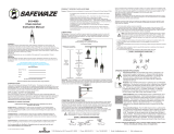
User Instructions for the 3M 2-Person Cable Horizontal Lifeline
System with PowerBrake.
Important: Keep these User Instructions for reference.
Horizontal Lifeline
User Instructions
3M
TM
2-Person Cable
with PowerBrake

Misuse or failure to follow warnings and instructions may result in serious personal injury or death.
1. Compliant fall protection and emergency rescue systems help prevent serious injury
during fall arrest. Users must read and understand the User Instructions provided with the
product and be properly trained by their employer prior to use per OSHA 29 CFR 1910.66
and 1926.503 and/or applicable local standards. Misuse or failure to follow warnings
and instructions may result in serious personal injury or death. For proper use, see
supervisor, User Instructions, or call 3M PSD Technical Service at 800-243-4630.
2. Do not bottom out the spring in the pre-tensioner.
3. Never use combinations of components or subsystems that may affect, or interfere with, the
safe function of each other.
4. Never attach the unused leg of the dual leg retractable back to the harness at any location
other than an approved lanyard storage keeper.
5. If inspection reveals any defect, inadequate maintenance, or unsafe condition, remove from
service until a “qualifi ed” person can determine the need for authorized repair or disposal.
6. Any equipment that has been subjected to the forces of arresting a fall must be removed from
service.
7. Any equipment that has a deployed fall indicator must be removed from service.
8. Only 3M, or persons or entities authorized in writing by 3M, shall make repairs or alterations
to the equipment.
GENERAL SAFETY INFORMATION
U
NDER PENALTY OF LAW
These User Instructions are not to be removed except by the user of this equipment. User
Instructions must always be available to the user.
FALL PROTECTION SYSTEM COMPONENTS
S
YSTEM COMPONENTS
A complete fall protection system consists of the following components: Anchorage, Body
Support, and Connecting Devices.
Note: For continuous protection, more than one system may be needed.
ANCHORAGE
An anchorage, as defi ned by OSHA 29 CFR 1926.502(d)(15) “shall be independent of any
anchorage being used to support or suspend platforms and capable of supporting at least 5,000
pounds (22.2 kN) per employee attached, or shall be designed, installed, and used as follows: as
part of a complete personal fall arrest system which maintains a safety factor of at least two; and
under the supervision of a “Qualifi ed” person.”
BODY SUPPORT
Body support is the component of a personal fall protection system that is worn on or around the
WARNING
1. Wear proper Personal Protective Equipment when performing Inspection, Cleaning and
Maintenance procedures. Safety glasses & gloves are recommended.
CAUTION
2

Misuse or failure to follow warnings and instructions may result in serious personal injury or death.
3
IMPORTANT
Before use, the user must read and understand these User Instructions. Keep these User
Instructions for reference.
USE INSTRUCTIONS AND LIMITATIONS
P
URPOSE
The 3M
TM
2-Person Cable Horizontal Lifeline with PowerBrake is an engineered fl exible
horizontal lifeline system, designed as part of a complete personal fall arrest system, to help limit
the fall arrest forces in the event of a fall.
USE INSTRUCTIONS
1. Failure to follow all instructions and limitations on the use of the 2-person cable
horizontal lifeline may result in serious personal injury or death.
2. Before using a personal fall arrest system, employees shall be trained in accordance with the
requirements of OSHA 29 CFR 1910.66 in the safe use of the system and its components.
3. Personal fall arrest systems, including the 2-person cable horizontal, shall be inspected prior
to each use for wear, damage, and other deterioration and defective components must be
immediately removed from service, in accordance with the requirements of OSHA 29 CFR
1910.66 and 1926.502.
4. The complete fall protection system must be planned (including all components, calculating
fall clearance, and swing fall) before using.
5. Users must have a rescue plan, and the means at hand to implement it, that provides for the
prompt rescue of employees in the event of a fall, or assures that employees are able to rescue
themselves.
6. Store the 2-person cable horizontal lifeline in a cool, dry, clean environment, out of direct
sunlight, when not in use.
7. After a fall occurs on the system, or if more than 6 inches of cable is pulled out of the 3M
TM
PowerBrake Energy Absorber, immediately remove from service for authorized repairs or
disposal.
USE LIMITATIONS
1. The 2-person cable horizontal lifeline is designed for up to two users at one time, per system,
with a capacity (including clothing, tools, etc.) up to 310 pounds (141 kg) total working
weight per user.
2. Only approved 3M components may be used with the 2-person cable horizontal lifeline.
CONNECTING DEVICES
A connecting method is the link between the body support and anchorage. Connecting methods
will vary depending on the application.
body. Per OSHA 29 CFR 1926.502 effective January 1, 1998, body belts are not acceptable as
part of a personal fall arrest system.
Note: The use of a body belt in a positioning device system is acceptable. Full body harnesses
must be used for all fall arrest systems.

Misuse or failure to follow warnings and instructions may result in serious personal injury or death.
4
3. The 2-person cable horizontal lifeline is designed to be used in temperatures ranging from
-40ºF to +130ºF (-40°C to +54°C).
4. Only connecting subsystems that limit the average arrest force to less than 900 pounds may
be used with the 2-person cable horizontal lifeline.
5. Do not expose the 2-person cable horizontal lifeline to chemicals or harsh solutions which
may have a harmful effect. Contact 3M Technical Service with any questions.
6. In accordance with the requirements of OSHA 29 CFR 1910.66, and 1926.502, the 2-person
cable horizontal lifeline must be installed and used under the supervision of a “qualifi ed”
person as defi ned by OSHA 29 CFR 1926.32(m).
7. Caution must be taken when using the 3M
TM
2-Person Cable Horizontal Lifeline with
PowerBrake near moving machinery, electrical hazards, sharp edges, or abrasive surfaces.
Contact with these elements may cause equipment failure, personal injury, or death.
8. Minors, pregnant women and anyone with a history of either back or neck problems should
not use this equipment.
9. Do not use or install equipment without proper training from a “competent person” as defi ned
by OSHA’s 29 CFR 1926.32(f).
10. Only 3M, or persons or entities authorized in writing by 3M, shall make repairs or alterations
to the equipment.
ANCHORAGES
All anchorages in which the 2-person cable horizontal lifeline attaches must meet the
requirements of OSHA 29 CFR 1910.66 and ANSI Z359.1-2007. OSHA states:
Anchorages to which personal fall arrest equipment is attached shall be capable of supporting
at least 5,000 pounds (22.2 kN) per employee attached, or shall be designed, installed, and used
as part of a complete personal fall arrest system which maintains a safety factor of at least two,
under the supervision of a “qualifi ed” person.
ANSI Z359.1-2007 states that anchorages in a personal fall arrest system must have a strength
capable of sustaining static loads, applied in all permitted directions by the system, of at least:
(a) two times the maximum arrest force permitted on the system when certifi cation exists, or
(b) 5,000 pounds (22.2kN) in the absence of certifi cation
The strength in (a) and (b) must be multiplied by the number of personal fall arrest systems
attached to the anchorage, when more then one personal fall arrest system is attached to the
anchorage.
The 2-person cable horizontal lifeline incorporates the 3M
TM
PowerBrake Energy Absorber
SWSW-18 as an inline energy absorber. It is designed to limit the maximum arrest load to less
than 2,500 lbf on the end anchorages. Therefore, the end anchorage must be rated at a minimum
strength of 5,000 lbf, twice the maximum arrest load.
ANCHORAGE REQUIREMENTS

Misuse or failure to follow warnings and instructions may result in serious personal injury or death.
5
ANCHORAGE CONNECTORS
Anchorage connectors are components that couple the personal fall arrest system to the
anchorage. The end anchorage connectors are designed to resist and transfer to the end anchorage
at least two times the maximum arrest load.
CONNECTION REQUIREMENTS
C
OMPATIBILITY LIMITATIONS
All connecting subsystems must only be coupled to compatible connectors. OSHA 29 CFR
1926.502 prohibits snaphooks from being engaged to certain objects unless two requirements
are met: snaphook must be a locking type and must be “designed for” making such a connection.
Under OSHA 29 CFR 1926.502 “designed for” means that the manufacturer of the snaphook
specifi cally designed the snaphook to be used to connect to the equipment in question. The
following connections must be avoided, because they can result in rollout* when a nonlocking
snaphook is used:
• Direct connection of a snaphook to horizontal lifeline.
• Two (or more) snaphooks connected to one D-ring.
• Two snaphooks connected to each other.
• A snaphook connected back on its integral lanyard.
• A snaphook connected to a webbing loop or webbing lanyard.
• Improper dimensions of the D-ring, rebar, or other connection point in relation to
the snaphook dimensions that would allow the snaphook keeper to be depressed
by a turning motion of the snaphook.
*Rollout: A process by which a snaphook or carabiner unintentionally disengages from another
connector or object to which it is coupled. (ANSI Z359.0)
SNAPHOOKS AND CARABINERS
Snaphooks and carabiners used in the 3M
TM
2-Person Cable Horizontal Lifeline with
PowerBrake, marked with the ANSI Z359.1-07 or ANSI Z359.12-09 standard, are self-locking
with a minimal tensile break strength of 5,000 pounds, and a 3,600 pound gate rating.
Snaphooks and carabiners marked to the ANSI Z359.1-1999 and/or CSA Z259.12-01 standards,
incorporate self-locking snaphooks and carabiners with minimal tensile break strength of 5,000
pounds, a minimum gate rating of 220 pounds, and a minimum side load gate rating of 350
pounds.
3M permits the attachment of 3M rebar hooks meeting the ANSI Z359.1-2007 or ANSI Z359.12-
2009 directly to the cable of the 2-person cable horizontal lifeline.
SYSTEM COMPONENTS
C
OMPATIBILITY LIMITATIONS
All components and subsystems used with the 2-person cable horizontal lifeline have been tested
as part of a pre-engineered fl exible horizontal lifeline system. Only 3M approved components
and subsystems are to be used with the 2-person cable horizontal lifeline.

Misuse or failure to follow warnings and instructions may result in serious personal injury or death.
6
ANCHORAGE CONNECTORS
3M
TM
SafeClaw 10,000 pound Concrete Anchor 4077
The SafeClaw 10,000 pound anchor is a reusable concrete anchor, designed to be used in
horizontal lifelines. The 10,000 pound rating is in any direction up to 90º when placed in
concrete with a compressive strength of 3,000 psi (20.7 MPa).
Heavy Duty Cross Arm Strap (4550-U)
Constructed with 1¾ inch polyester webbing and a 3 inch nylon abrasion pad, the 6 foot cross
arm strap is designed to wrap around structures to create a 5,000 lb anchor point.
TENSIONERS
Turnbuckle (SWSW-04)
The jaw and jaw 5⁄8 inch turnbuckle is constructed of forged galvanized steel and adjusts from 18
to 28 inches.
Pre-Tensioner (SWPC-17)
The pre-tensioner is designed to easily identify if the 3M
TM
2-Person Cable Horizontal Lifeline
with PowerBrake has been properly tensioned. The pre-tensioner is constructed out of plate
steel/stainless steel.
LIFELINE
Cable (SWMS-30, SWMS-60, SWMS-30-SS, SWMS-60-SS)
The cable in the 2-person cable horizontal lifeline is 7x19 ⁄ inch galvanized or 304 stainless
steel aircraft cable. The cable comes with one end fi nished (thimble and two swages), and the
other end unfi nished for adjustment in length with two fi st grips (SWSW-11) and a thimble
(SWSW-12T).
3M
TM
PowerBrake Energy Absorber SWSW-18
The 3M PowerBrake energy absorber is designed to limit the maximum arrest load to less than
2,500 lbf on the end anchorages.
HARDWARE
Snaphooks and carabiners used with the 2-person cable horizontal lifeline marked with the
ANSI Z359.1-07 and/or ANSI Z359.12-09 standard are self-locking with a minimal tensile break
strength of 5,000 pounds, and a 3,600 pound gate rating.
Snaphooks and carabiners marked to the ANSI Z359.1-1999 standard incorporate self-locking
snaphooks and carabiners with minimal tensile break strength of 5,000 pounds, a minimum gate
rating of 220 pounds and a minimum side load gate rating of 350 pounds.

Misuse or failure to follow warnings and instructions may result in serious personal injury or death.
7
INSTALLATION
B
EFORE EACH USE
Users of personal fall arrest systems must have a rescue plan in place, if the user cannot rescue
themselves, as well as the means to carry out the rescue.
The user must read and understand these User Instructions, as well as the User Instructions for
every component/subsystem of the personal fall arrest system.
The entire 3M
TM
2-Person Cable Horizontal Lifeline with PowerBrake system, and its
subsystems, must be inspected prior to each use. Check the 3M
TM
PowerBrake Energy Absorber
in the lifeline to ensure that no more than 6 inches of cable have been pulled from the unit.
All snaphooks and carabiners must be able to self-close and lock. Check the operation of
self-retracting lanyards by pulling smoothly on the lifeline, then pull sharply on the lifeline to
engage the locking mechanism. All webbing must be inspected for tears, cuts, fraying, abrasion,
discoloration, or other signs of wear and damage. Sewn terminations should be secure, complete,
and not visibly damaged. Cable must be inspected for kinks, broken strands, corrosion, abrasion,
or other signs of wear and damage. Swaged terminations should be secure with the thimble
tight and not visibly damaged. System must be properly tensioned. No load indicators shall
be deployed. Damaged and other deteriorated and defective components must be immediately
removed from service, in accordance with the requirements of OSHA 29 CFR 1910.66 and
1926.502.
SWING FALLS
To minimize the possibility of a swing fall, work as directly under the lifeline as possible.
Striking objects horizontally, due to the pendulum affect, may cause serious injury. Swing
falls also increase the vertical fall distance of a worker, compared to a fall directly below the
anchorage connector. Swing falls may be controlled by using anchorage connectors that move
with a worker to a point overhead.
STEP 1. INSTALL ANCHORAGE CONNECTOR
Select and install the appropriate anchorage connector for your 2-person cable horizontal lifeline.
STEP 2. CONNECT 3M
TM
POWERBRAKE ENERGY ABSORBER SWSW-18
Connect the 3M PowerBrake energy absorber using the supplied carabiner to the anchorage
connector at one end of the system. The end with the 3M PowerBrake energy absorber of the
2-person cable horizontal lifeline is the live-end of the system. The dead-end of the system is the
end with the pre-tensioner and tensioning device.

Misuse or failure to follow warnings and instructions may result in serious personal injury or death.
8
STEP 4. CONNECT PRE-TENSIONER (SWPC-17)
Connect the other end of the turnbuckle to the eye of the pre-tensioner.
SWSW-18
PowerBrake
0210-07
Carabiner
SWMS-XX
Cable
SWSW-11
Fist Grips
SWPC-17
Pre-Tensioner
SWSW-04
Turnbuckle
STEP 3. INSTALL TURNBUCKLE (SWSW-04)
Extend the jaw and jaw turnbuckle until one inch of threaded rod remains visible on each
end inside the turnbuckle body. Connect one end of the turnbuckle directly to the anchorage
connector.
STEP 5. ATTACH CABLE (SWMS-XX)
Attach the fi nished end of the cable to the cable of the 3M
TM
PowerBrake Energy Absorber using
an approved carabiner. The unfi nished end of the cable is for system length adjustment.
Take the SWSW-12T thimble and open by twisting the ends apart enough to fi t over the rod
on the pre-tensioner. Do not attempt to pull the ends of the thimble directly away from each
other. Twist back to original position. Turn back cable over the thimble until the desired length
is reached and apply fi rst SWSW-11 fi st grip 5 inches from the thimble. Use torque wrench to
tighten fi st grip evenly, alternating from one nut to the other until reaching 30 ft. lbs. of torque.
Apply the second fi st grip as near the thimble as possible.
STEP 6. TENSION THE SYSTEM
Use the turnbuckle to adjust tension in the system. The yellow indicator sleeve on the bolt in the
pre-tensioner must extend at least a ⅜ inches, but not exceed ⁄ inches.
Warning: Do not bottom out the spring in the pre-tensioner.
⅜ inches - ⁄ inches

Misuse or failure to follow warnings and instructions may result in serious personal injury or death.
9
HOUSING OF THE SRL TO HARNESS
Lighter weight self-retracting lanyards may be attached by the housing connector directly to the
primary dorsal D-ring of the full body harness. The opposing end is connected to the cable of the
2-person cable horizontal lifeline.
DUAL LEG RETRACTABLES
Attach the dual leg retractable directly to the dorsal D-Ring of the full body harness. Attach
one leg of the dual leg retractable to the cable of the 2-person cable horizontal lifeline, and the
unused leg to an approved lanyard storage keeper on the harness.
Warning: Never attach the unused leg of the dual leg retractable back to the harness at
any location other than an approved lanyard storage keeper.
INSPECTION
F
REQUENCY
All components of the 2-person cable horizontal lifeline must be inspected prior to each use,
and annually by an OSHA defi ned “competent person” other than the user. Local, state,
governmental and jurisdictional agencies governing occupational safety may require the user to
conduct more frequent or mandatory inspections.
SELF-RETRACTING LANYARDS (SRLS)
Attach the housing connector of the self-retracting lanyard to the cable of the 2-person cable
horizontal lifeline. The opposing end is connected to the primary dorsal D-ring of the full body
harness. Never attach an additional energy absorbing lanyard, or self-retracting lanyard, to
lengthen the lifeline.
Warning: Never use combinations of components or subsystems that may affect, or
interfere with, the safe function of each other.
CONNECTION
NUMBER OF USERS
The 3M
TM
2-Person Cable Horizontal Lifeline with PowerBrake is designed for up to two users
at one time, with each user having a combined tool and body weight of up to 310 pounds (141
kg) total working weight.

Misuse or failure to follow warnings and instructions may result in serious personal injury or death.
10
CRITERIA
Warning: If inspection reveals any defect, inadequate maintenance, or unsafe condition,
remove from service until a “qualifi ed” person can determine the need for authorized
repair or disposal.
Warning: Any equipment that has been subjected to the forces of arresting a fall must be
removed from service.
Warning: Any equipment that has a deployed fall indicator must be removed from
service.
All components and subsystems of the 3M
TM
2-Person Cable Horizontal Lifeline with
PowerBrake must be inspected.
All markings must be legible and attached to the product.
Check the 3M
TM
PowerBrake Energy Absorber in the lifeline to ensure that no more than 6
inches of cable have been pulled from the unit.
Cable must be inspected for kinks, broken strands, corrosion, abrasion, or other signs of wear
and/or damage. Swaged terminations should be secure with the thimble tight, and not visibly
damaged.
All snaphooks and carabiners must be able to self-close and lock. All hardware shall be free of
cracks, sharp edges, deformation, corrosion, or any evidence of defect or damage to.
All components of the full body harness must be inspected. See user instructions supplied with
the full body harness.
No more than 6 inches
CLEANING, MAINTENANCE, STORAGE
Caution: Wear proper Personal Protective Equipment when performing Inspection,
Cleaning and Maintenance procedures. Safety glasses & gloves are recommended.
CLEANING
The 2-person cable horizontal lifeline can wiped down with a mild detergent and clean water
solution, and rinsed with a dampened clean cloth to remove detergent. The hardware can also be
wiped down to remove grease, or dirt with a clean dry cloth.

Misuse or failure to follow warnings and instructions may result in serious personal injury or death.
11
MAINTENANCE
Any 2-person cable horizontal lifeline components requiring maintenance must be tagged
“unusable” and removed from service.
Warning: Only 3M, or persons or entities authorized in writing by 3M, shall make
repairs or alterations to the equipment.
Cleaning maintenance may be performed by the user.
System Length One User Two Users
15 Feet (4.6 m) 6'1" (1.8 m) 7'2" (2.2 m)
20 Feet (6.1 m) 6'5" (2.0 m) 7’11” (2.4 m)
25 Feet (7.6 m) 6'10" (2.1 m) 8’8” (2.6 m)
30 Feet (9.1 m) 7’2” (2.2 m) 9’5” (2.9 m)
35 Feet (10.7 m) 7’6” (2.3 m) 10’2” (3.1 m)
40 Feet (12.2 m) 7’10” (2.4 m) 10’10” (3.3 m)
45 Feet (13.7 m) 8’2” (2.5 m) 11’7” (3.5 m)
50 Feet (15.2 m) 8’7” (2.6 m) 12’4” (3.8 m)
55 Feet (16.8 m) 8’11” (2.7 m) 13’1” (4.0 m)
60 Feet (18.3 m) 9’3” (2.8 m) 13’10” (4.2 m)
CLEARANCE REQUIREMENTS
C
LEARANCE CHART
The clearance chart below shows the required distance needed from the walking/working surface
to the ground or nearest obstruction below.
STORAGE
The 3M
TM
2-Person Cable Horizontal Lifeline with PowerBrake should be stored in a cool,
dry place out of direct sunlight when not in use. Do not store in areas where damage from
environmental factors such as heat, light, excessive moisture, oil, chemicals and their vapors,
or other degrading elements may be present. Do not store damaged equipment or equipment
in need of maintenance in the same area as product approved for use. Equipment that has been
stored for an extended period must be inspected as defi ned in these User Instructions prior to use.

50
Product Warranty, Limited Remedy, andLimitation of Liability
WARRANTY: THE FOLLOWING IS MADE IN LIEU OF ALL WARRANTIES OR
CONDITIONS, EXPRESS OR IMPLIED, INCLUDING THE IMPLIED WARRANTIES OR
CONDITIONS OF MERCHANTABILITY OR FITNESS FOR A PARTICULAR PURPOSE.
Equipment offered by 3M is warranted against factory defects in workmanship and materials for a
period of one year from date of installation or fi rst use by the original owner.
LIMITED REMEDY: Upon notice in writing, 3M will repair or replace all defective items at
3M’s sole discretion. 3M reserves the right to require that the defective item be returned to its
plant for inspection before determining the appropriate course of action. Warranty does not cover
equipment damage resulting from wear, abuse, damage in transit, failure to maintain the product
or other damage beyond the control of 3M. 3M shall be the sole judge of product condition
and warranty options. This warranty applies only to original purchaser and is the only warranty
applicable to this product. Please contact 3M technical service department at 800-243-4630 for
assistance.
LIMITATION OF LIABILITY: IN NO EVENT WILL 3M BE LIABLE FOR ANY
INDIRECT, INCIDENTAL, SPECIAL OR CONSEQUENTIAL DAMAGES INCLUDING,
BUT NOT LIMITED TO LOSS OF PROFITS, IN ANY WAY RELATED TO THE PRODUCTS
REGARDLESS OF THE LEGAL THEORY ASSERTED.
Garantie du produit, limite de recours et limite de responsabilité
GARANTIE : CE QUI SUIT TIENT LIEU DE TOUTE GARANTIE OU CONDITION
EXPLICITE OU IMPLICITE, Y COMPRIS LES GARANTIES OU CONDITIONS IMPLICITES
DE QUALITÉ MARCHANDE ET D’ADAPTATION À UN USAGE PARTICULIER. Le matériel
offert par 3M est garanti contre les défauts de fabrication et de matériau pendant une période de
un (1) an à partir de la date d’installation ou de la première utilisation par le propriétaire d’origine
du produit.
LIMITE DE RECOURS : Sur avis écrit, 3M, à son gré, réparera ou remplacera tout article
défectueux. 3M se réserve toutefois le droit d’exiger que l’article défectueux soit retourné à son
usine pour inspection avant de déterminer la mesure appropriée à prendre à l’égard de celui-ci. La
garantie ne couvre pas le matériel endommagé par l’usure, une utilisation abusive, le transport, un
manque d’entretien ou tout autre dommage indépendant de la volonté de 3M. 3M est le seul juge
quant à l’état du produit et des options de garantie. La présente garantie s’applique uniquement
à l’acheteur d’origine et elle seule s’applique à ce produit. Pour obtenir de l’aide, veuillez
communiquer avec le Service technique de 3M au 1 800 267-4414.
LIMITE DE RESPONSABILITÉ : 3M NE PEUT EN AUCUN CAS ÊTRE TENUE
RESPONSABLE DES DOMMAGES INDIRECTS, FORTUITS, SPÉCIAUX OU
CONSÉQUENTS, Y COMPRIS, MAIS SANS S’Y LIMITER, DES PERTES DE PROFITS,
RELATIVEMENT AUX PRODUITS, QUELLE QUE SOIT LA THÉORIE JURIDIQUE DONT
ON SE PRÉVAUT.

52
Pensez au recyclage. Imprimé aux É.-U.
© 2015
3M est une marque commerciale de 3M
Company utilisée sous licence au Canada. Tous
droits réservés.
Division de la sécurité personnelle
de 3M
C.P. 5757
London (Ontario) N6A 4T1
Assistance technique :
800-267-4414
www.3M.com/FallProtection
www.3M.com/PPESafety
Please recycle. Printed in USA.
© 3M 2015
3M is a trademark of 3M Company, used under
license in Canada. All rights reserved.
IM-0009C Rev A (5-2015) 34-8717-2570-0
3M Personal Safety Division
3M Center Building 235-2W-70
Saint Paul, MN 55144-1000
USA
Technical Service:
800-243-4630 in U.S.
800-267-4414 in Canada
www.3M.com/FallProtection
ISO 9001
FM 573368
Recicle. Impresso nos EUA
© 2015
3M é uma marca registrada da 3M Company
utilizada sob licença no Canadá. Todos os
direitos reservados.
3M Divisão de Segurança Pessoal
3M Brasil
Assistência Técnica: 0800 0550705
3M División de Seguridad Personal
3M Argentina
3M Bolivia
Asistencia Técnica: 315-9000
3M Chile
Asistencia Técnica: 600-300-3636
3M Colombia
Asistencia Técnica: 018000113636 opción 2
3M Ecuador
Asistencia Técnica: 04-372-1800
3M Mexico
Asistencia Técnica: 01800712 06 46
Por favor, recicle. Impreso en los EE. UU.
© 2015
3M es una marca comercial de 3M Company
utilizada bajo licencia en Canadá. Todos los
derechos reservados.
3M Perú
Atención al Consumidor: 01-702-8086
3M Uruguay
Asistencia al Consumidor: 000-598-26283636
3M Venezuela
Asistencia Técnica: 0-800-TRESMMM
(0-800-8737666)
/