Page is loading ...

MB51-PS0 Quick Reference Guide/ 快速测试参考指南
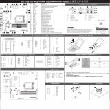
No. Code Descripon
9 P12V_AUX1 2 x 4 pin power connector (for CPU)
10 SYS_FAN5 System fan connector #5
11 SSATA5 sSATA 6Gb/s connector #5
12 SSATA4 sSATA 6Gb/s connector #4
13 SSATA2 sSATA 6Gb/s connector #2
14 SSATA3 sSATA 6Gb/s connector #3
15 SSATA1 sSATA 6Gb/s connector #1
16 SSATA0 sSATA 6Gb/s connector #0
17 SATA_6_7 SATA 6Gb/s connector #6/#7
18 SATA_4_5 SATA 6Gb/s connector #4/#5
19 SATA_2_3 SATA 6Gb/s connector #2/#3
20 SATA_0_1 SATA 6Gb/s connector #0/#1
21 U2_0 SlimSAS connector (SATA signal)
22 SW_RAID VROC upgrade module connector
23 SYS_FAN3 System fan connector #3
24 SYS_FAN2 System fan connector #2
25 SYS_FAN1 System fan connector #1
26 SSATA_SGP4 sSATA SGPIO header #4
27 BP_1 HDD back plane board header
28 SSATA_SGP1 SATA SGPIO header #1
29 SSATA_SGP2 SATA SGPIO header #2
30 M2_MKEY M.2 connector
31 SSATA_SGP3 SATA SGPIO header #3
32 F_USB3 USB 3.0 header
33 CASE_OPEN Case open header
34 FP_1 Front panel header
35 IPMB IPMB connector
36 LED_BMC BMC firmware readiness LED
37 COM2 Serial port header
38 PCIE_4 PCIe x16 slot #4 (Gen3 x16)
39 PCIE_6 PCIe x16 slot #6 (Gen3 x16)
40 BAT Baery socket
41 LPC_TPM TPM module connector
1 2 3 4 5
678 9 10
12
11
13
14
16
15
17 18 1920 21
22
23
24
25
26
32
33
34
35
36
37
38 39
40
41
31
CPU
28
27 29
31
30
No. Code Descripon
1 COM1_VGA Serial port (top)/VGA port (boom)
2 USB3_MLAN Server management LAN port (top)/USB 3.0 ports (boom)
3 SW_ID ID buon with LED
4 LAN1 10GbE LAN port #1
5 LAN2 10GbE LAN port #2
6 CPU_FAN CPU fan connector
7 SYS_FAN4 System fan connector#4
8 ATX1 2 x12 pin system power connector
Front Panel Header
1
2423
2
No. Pin Define
1 Power LED+
3 No Pin
5 Power LED-
7 HDD LED+
9 HDD LED-
11 Power Buon
13 GND
15 Reset Buon
17 GND
19 ID Buon
21 GND
23 NMI Switch
No. Pin Define
2 5V Standby
4 ID LED+
6 ID LED-
8 System Status LED+
10 System Status LED-
12 LAN1 Acve LED+
14 LAN1 Link LED-
16 SMBus Data
18 SMBus Clock
20 Case Open
22 LAN2 Acve LED+
24 LAN2 Link LED-
HDD Back Plane Board Header
No. Pin Define
1 No Connect
3 Ground
5 BP SGLD
7 BP SGCLK
9 BP_ALED_N
11 IRQ_FAN_12V_GATE_N_BUF
13 SMB_BP_BMC_CLK
15 SMB_BP_BMC_DATA
17 SMB_BP_NVME_CLK
19 SMB_BP_NVME_DATA
21 SMB_LVC3_CPU0_PE_HP_SCL
23 SMB_LVC3_CPU0_PE_HP_SDA
25 TP
27 TP
29 P_3V3_AUX
No. Pin Define
2 Throle
4 FAN Gate
6 Ground
8 Reset
10 BP LED RED
12 No Connect
14 GND
16 RST_BP_BUF_N
18 Ground
20 BMC_RST_I2C_BP
22 FAN Type
24 Ground
26 Ground
28 Ground
30 P_3V3_AUX
3029
1 2
ATX Power/
No. Pin Define
1 GND
2 GND
3 GND
4 GND
5 +12V
6 +12V
7 +12V
8 +12V
24
12
13
1
No. Pin Define
1 3.3V
2 3.3V
3 GND
4 +5V
5 GND
6 +5V
7 GND
8 Power Good
9 5VSB
10 +12V
11 +12V
12 3.3V
1 5
4 8
No. Pin Define
13 3.3V
14 -12V
15 GND
16 PS_ON
17 GND
18 GND
19 GND
20 -5V
21 +5V
22 +5V
23 +5V
24 GND
PMBUS
1
5No. Pin Define
1 PMBus Clock
2 PMBus Data
3 PMBus Alert
4 GND
5 3.3V Sense
Memory Populaon Configuraon/ 安装内存
DIMM
Capacity
(GB) 1 Slot per
Channel 2 Slot per Channel
Speed (MT/s); Voltage (V)
Slot Per Channel (SPC)
DIMM Per Channel (DPC)
1DPC 1DPC 2DPC
1.2V
2666 2666 2666
1.2V 1.2V
Ranks Per
DIMM and
Data Width
4Gb DRAM 8Gb DRAM
8GB 16GB
8GB
4GB
32GB
16GB
16GB
8GB
Type
RDIMM
LRDIMM
SRx4
SRx8
DRx8
DRx4
64GB32GBQRx4
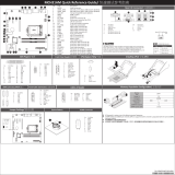
No. Desripon
1 10GbE Ethernet LAN port #2
2 10GbE Ethernet LAN port #1
3 ID buon with LED
4 Server Management 10/100/1000 LAN port
5 USB 3.0 ports
6 Serial port
7 VGA port
1 2
7
6
Off 10Mbps data rate
State Description
Yellow On 1Gbps data rate
Green On 100Mbps data rate
10/100/1000 LAN LED:
Off 100Mbps data rate
State Description
Yellow On 10Gbps data rate
Green On 1Gbps data rate
10GbE LAN LED:ID buon/LED:
Blue On System identifcation
is active.
Off System identifcation
is disabled.
State Description
Speed LED Link/Acvity
LED
5
3
4
SATA Connector SATA SGPIO
9
1
No. Pin Define
1 GND
2 TXP
3 TXN
4 GND
5 RXN
6 RXP
7 GND
8 GND
9 GND
5
1
No. Pin Define
1 Data Out
2 GND
3 No Connect
4 Load
5 Clock
NOTE!
PCB 1.0: Pin3: Load, Pin4: Load
PCB 1.1: Pin3: No Connect, Pin4: Load
TPM Connector/ TPM Module
1314
12
No. Pin Define
1 Clock_LPC0_TPM
3 LPC_Reset_N
5 LPC_LAD0_TPM
7 LPC_LAD1_TPM
9 LPC_LAD2_ESPI_IO2_TPM
11 LPC_LAD3_ESPI_IO3_TPM
13 LPC_LFRAME_N_TPM_N
IPMB
4
1No. Pin Define
1 Clock
2 Data
3 GND
4 VCC
No. Pin Define
2 P_3V3_AUX
4 P_3V3
6 LPC_IRQ
8 No Connect
10 No Pin
12 GND
14 GND
CPU/System FAN/
4 1
1
4
No. Pin Define
1 GND
2 +12V
3 Sense
4 Speed Control
USB 3.0 Header
120
1011
Serial Port Header
No. Pin Define
1 NDCD-
2 NSIN
3 NSOUT
4 NDTR-
5 GND
6 NDSR-
7 NRTS-
8 NCTS-
9 NRI-
10 No Pin
2 1
10 9
No. Pin Define
1 Power
2 IntA_P1_SSRX-
3 IntA_P1_SSRX+
4 GND
5 IntA_P1_SSTX-
6 IntA_P1_SSTX+
7 GND
8 IntA_P1_D-
9 IntA_P1_D+
10 NC
No. Pin Define
11 IntA_P2_D+
12 IntA_P2_D-
13 GND
14 IntA_P2_SSTX+
15 IntA_P2_SSTX-
16 GND
17 IntA_P2_SSRX+
18 IntA_P2_SSRX-
19 Power
20 No Pin
1
2
3
4
5
Jumper Sengs/ 跳线设置
No. Desripon
1 Clear CMOS Jumper
1-2 Close: Normal operaon (Default seng)
2-3 Close: Clear CMOS data.
2 ME Recovery Jumper
1-2 Close: Normal operaon. (Default seng)
2-3 Close: BIOS recovery mode.
3 BIOS Recovery Jumper
1-2 Close: Normal operaon. (Default seng)
2-3 Close: BIOS recovery mode.
4 ME Update Force Jumper
1-2 Close: Normal operaon. (Default seng)
2-3 Close: Fore ME update.
5 S3 Power On Select Jumper
1-2 Close: Stop an inial power on when BMC is not ready.
2-3 Close: Keep inial power on. (Default seng)
Rear I/O Connector/ 后面板接口
BMC Firmware Readiness LED
State Descripon
On BMC firmware is inial
Blink BMC firmware is ready
Off AC loss
BMC Firmware Readiness LED (LED_BMC)
2260
2240
2280
1
1
2
2
System Baery
M.2 Module
VROC Module
/