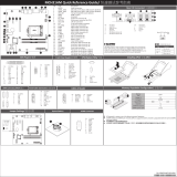
No. Code Descripon
1 SW_ID ID buon with LED
2 R_USB1 USB 2.0 ports
3 USB3_LAN Server managemnt LAN port (top)/USB 3.0 port (boom)
4 LED_LAN1 SFP+ LAN port #1 acve/link LEDs
5 SFP+_1/SFP+_2 SFP+ LAN port #1/SFP+ LAN port#2
6 LED_LAN2 SFP+ LAN port #2 acve/link LEDs
7 COM1_VGA Serial port (top) / VGA port (boom)
8 SYS_FAN3 System fan connector #3
9 PMBUS_SEL PMBus select jumper
10 S3_MASK S3 power on select jumper
11 PMBUS PMBus connector
12 LED_BMC1 BMC firmware readiness LED
13 TPM_LPC TPM connector
14 P2 2 x 12 pin main power connector
15 P4 2 x 4 pin power connector (for memory)
16 P3 2 x 4 pin power connector (for CPU)
17 CPU1_FAN CPU fan connector #1
18 CPU0_FAN CPU fan connector #0
19 BIOS_PWD Clearing Supervisor Password jumper
20 BIOS_RCVR BIOS recovery jumper
21 SLSAS_0 Slimline connector #0 (SATA 6Gb/s signal)
22 SLSAS_1 Slimline connector #1 (SATA 6Gb/s signal)
23 SLSAS_2 Slimline connector #2 (SATA 6Gb/s signal)
24 SLSAS_3 Slimline connector #3 (SATA 6Gb/s signal)
25 FP_1 Front panel header
26 BP_1 HDD back plane board header
27 M2_SK1 M.2 slot (Gen3/x4)
28 F_USB1 USB 3.0 header
29 SYS_FAN1 System fan connector #1
30 F_USB2 USB 2.0 header
31 SYS_FAN4 System fan connector #4
32 SYS_FAN5 System fan connector #5
33 SYS_FAN2 System fan connector #2
No. Code Descripon
34 COM2 Serial port cable connector
35 PCIE_1 PCIe x16 slot (Gen3/x16)
36 PCIE_2 PCIe x8 slot (Gen3/x8)
37 PCIE_3 PCIe x16 slot (Gen3/x16)
38 PCIE_4 PCIe x16 slot (Gen3/x16)
39 PCIE_5 PCIe x16 slot (Gen3/x8)
40 PCIE_6 PCIe x16 slot (Gen3/x16)
41 PCIE_7 PCIe x8 slot (Gen3/x8)
42 BAT Baery socket
43 IPMB IPMB connector
44 CLR_CMOS Clear CMOS jumper
Front Panel Header /
No. Pin Define
1 Power LED+
3 No Pin
5 Power LED-
7 HDD LED+
9 HDD LED-
11 Power Buon
13 GND
15 Reset Buon
17 GND
19 ID Buon
21 GND
23 NMI Switch
No. Pin Define
2 5V Standby
4 ID LED+
6 ID LED-
8 System Status LED+
10 System Status LED-
12 LAN1 Acve LED+
14 LAN1 Link LED-
16 SMBus Data
18 SMBus Clock
20 Case Open
22 LAN2 Acve LED+
24 LAN2 Link LED-
1
2423
2
HDD Back Plane Board Header/ 硬盤背板排針
No. Pin Define
1 HP_ALERT
3 GND
5 BPMI_LOAD
7 BPMI_CLK
9 GLED_AMB_N
11 FAN_IRQ_N
13 BP_SCL
15 BP_SDA
17 SMB_U2_TMP_SCL
19 SMB_U2_TMP_SDA
21 PH_HP_SCL0
23 PH_HP_SDA0
25 No Connect
27 No Connect
29 P_3V3_AUX
No. Pin Define
2 BPMI_DIN/OUT
4 BPMI_DIN/IN
6 GND
8 PLD_Program_ENABLE
10 GLED_GRN_N
12 No Connect
14 GND
16 BP_RST_N
18 GND
20 I2C_DEV_RST
22 GND
24 GND
26 GND
28 GND
30 P_3V3_AUX
1 2
29 30
ATX Power/
8 4
5 1
No. Pin Define
1 GND
2 GND
3 GND
4 GND
5 +12V
6 +12V
7 +12V
8 +12V
1
1224
13
No. Pin Define
1 3.3V
2 3.3V
3 GND
4 +5V
5 GND
6 +5V
7 GND
8 Power Good
9 5VSB
10 +12V
11 +12V
12 3.3V
No. Pin Define
13 3.3V
14 -12V
15 GND
16 PS_ON
17 GND
18 GND
19 GND
20 -5V
21 +5V
22 +5V
23 +5V
24 GND
1
5
PMBUS
No. Pin Define
1 PMBus Clock
2 PMBus Data
3 PMBus Alert
4 GND
5 3.3V Sense
Installing CPU/Heatsink
3
1
2
1
External cap
2
3
CPU
4
5
6
7
1
3
2
8
9
3
1
2
4NOTE!
When installing the heatsink to CPU,
use T20-Lobe driver to ghten 4 capve nuts
in sequence as 1-4.
The screw ghtening torque:
16.1 ± 1.2 kgf-cm (14.0± 1.0 lbf-in)
Memory Populaon Configuraon/ 安装内存
NOTE!
1R: 1 package rank of SDP DRAMs
2R: 2 package rank of SDP DRAMs
2DR: 2 package rank of DDP DRAMs
4DR: 4 package rank of DDP DRAMs
1S2R/1S4R/1S8R: 1 package rank of 2/4/8 high 3DS DRAMs
2S2R/2S4R/2S8R: 2 package rank of 2/4/8 high 3DS DRAMs
DIMM must be populated in sequenal alphabec order, starng with bank A.
When only one DIMM is used, it must be populated in memory slot A1.
DIMMs
Populated
DIMM
1R
2
1-- --
2 --
1
--
--
-- --
-- Not Supported
2666
2666
Not Supported
Not Supported
2133
1
1
--
--2
1
1
--
-- --
--
--
2133
Not Supported
2133
1
11
1
2
4DR 1.2V
2S4R
Frequency (MT/s)
RDIMM Maximum Frequency Supported Table
DDR Populaon Table
LRDIMM Maximum Frequency Supported Table
DIMMs
Populated DIMM0 DIMM1
-- 11
1 12
DIMM
DIMMs
Populated 1R
-- --
--
2 --
--
-- --
--
--
--
--
2666
2400
Not Supported
2133
2133
2133
1
1
2
1
1
1
-- --
--
--
Not Supported
Not Supported
Not Supported
1
11
1
2
4DR 1.2V
2R
2DR
2S2R
2S4R
Frequency (MT/s)
2
1
10
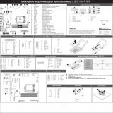
Rear I/O Connector/ 后面板接口
No. Desripon
1 Serial port
2 VGA port
3 SFP+ LAN port #2 acve/link LEDs
4 SFP+ LAN port #2
5 SFP+ LAN port #1
6 SFP+ LAN port #1 acve/link LEDs
7 10/100/1000 Server Management LAN port
8 USB 3.0 ports
9 USB 2.0 ports
10 ID buon with LED
Off
State Description
Yellow On
Green On
1Gbps data rate
100Mbps data rate
10Mbps data rate
10/100/1000 LAN LED:
Speed LED Link/Acvity
LED
2
4 5 6
7
8
9
3
1
ID buon/LED:
Blue On System identifcation is active.
Off System identifcation is disabled.
State Description
Description
State
Yellow On 1 Gbps data rate
Green On 10 Gbps data rate
SFP+ LAN Link and Speed LED:
State Description
Green On Link between system and network or no access.
Green Blink Data transmission or receiving.
Off No data transmission or receiving.
SFP+ LAN Acve LED:
Green/Yellow Link LED
Green Acve LED
TPM Connector/
1
2
13
14
No. Pin Define
1 Clock
2 P_3V3_AUX
3 LPC_RST
4 P3V3
5 LPC_LAD0
6 IRQ_SERIAL
7 LPC_LAD1
No. Pin Define
8 No Connect
9 LPC_LAD2
10 No Pin
11 LPC_LAD3
12 GND
13 LPC_FRAME_N
14 GND
3
IPMB
1
No. Pin Define
1 Clock
2 GND
3 Data
COM2 Connector
21
109
No. Pin Define
1 NDCD-
2 NSIN
3 NSOUT
4 NDTR-
5 GND
No. Pin Define
6 NDSR-
7 NRTS-
8 NCTS-
9 NRI-
10 No Pin
CPU/System FAN/
4
1
1
4No. Pin Define
1 GND
2 +12V
3 Sense
4 Speed Control
10
2
9
1
USB 2.0 Header
No. Pin Define
1 Power (5V)
2 Power (5V)
3 USB DX-
4 USB DY-
5 USB DX+
No. Pin Define
6 USB DY+
7 GND
8 GND
9 No Pin
10 No Connect
USB 3.0 Header
120
1011
No. Pin Define
1 Power
2 IntA_P1_SSRX-
3 IntA_P1_SSRX+
4 GND
5 IntA_P1_SSTX-
6 IntA_P1_SSTX+
7 GND
8 IntA_P1_D-
9 IntA_P1_D+
10 NC
No. Pin Define
11 IntA_P2_D+
12 IntA_P2_D-
13 GND
14 IntA_P2_SSTX+
15 IntA_P2_SSTX-
16 GND
17 IntA_P2_SSRX+
18 IntA_P2_SSRX-
19 Power
20 No Pin
BMC Firmware Readiness LED
State Descripon
On BMC firmware is inial
Blink BMC firmware is ready
Off AC loss
MZ31-AR0 Quick Reference Guide/ 快速测试参考指南
Jumper Sengs/ 跳线设置
No. Desripon
1 Clear CMOS Jumper
1-2 Closed: Normal operaon (Default seng)
2-3 Closed: Clear CMOS data.
2 PMBus Address Selecon Jumper
1-2 Closed: From core chipset.
2-3 Closed: From BMC. (Default seng)
3 S3 Power On Select Jumper
1-2 Close: Stop an inial power on when BMC is not ready.
2-3 Close: Keep inial power on. (Default seng)
4 Clearing Supervisor Password Jumper
1-2 Close: Normal operaon. (Default seng)
2-3 Close: Skip supervisor password.
5 BIOS Recovery Jumper
1-2 Close: Normal operaon. (Default seng)
2-3 Close: BIOS recovery mode.
1 2 3 4 5 6 7
8
9
10
12 11
14
15
16
13
18
17
1920
22
21
24
25
26
27
28
29
30
31
32
33
34
35 36 37 38 39 40 41
42
43 44
23
1
2
3
45
PN:25ME0-MZ3101-Q0H