Page is loading ...

312-102 Up/Down Crawl Thru (Port) Page 1 of 1
Rev.02/20/2020
SportsPlay Equipment, Inc. www.sportsplayinc.com (800) 727-8180
IMPORTANT
PLEASE READ THESE INSTRUCTIONS BEFORE COMMENCING ASSEMBLY. All
equipment must be installed in accordance with these instructions.
Check your shipment against Bill of Lading and Parts list. Any missing
or broken parts must be reported to your distributor within 10 days of
receipt of your order. When properly installed and maintained,
equipment will give many years of Safe, Trouble-Free use. Periodically
check for loose or broken parts. Loose bolts must be tightened and
broken parts must be replaced as they can possibly create dangerous
situations leading to unnecessary accidents. Resilient Surfacing
should be used under all playground equipment. Appropriate
publications, available at no charge, from the Consumer Product Safety
Commission, include “A Handbook for Public Playground Safety”. You can
receive your free copy by calling 1-301-504-7908.
PACKING LIST
1 CTN Hardware Bag 16 605-506
8 103-009 Rings 12 pr 415-515
8 313-501 Angle 8 355-905
1 BDL 2 603-906 Aluminum Board 4 315-961
1 BDL 4 303-203 Supports 8 116-545
1 BDL 4 303-201 Rails 28 116-535
1 BDL 2 313-209 Support 4’ x 1 5/8” 8 116-530
1 PIPE 1 313-620 Leg 16 126-504
1 PIPE 1 313-620 Leg 16 316-501
44 326-501
16 226-501
46 216-512
2416-350
1 805-532
1 805-534
1
HARDWARE BAG
Clips
1 5/8” T-Clamp
1” Black Plastic Plug
1 5/8” Plastic Cap
5/16” x 2 ½” Button Head Bolt
5/16” x 1 ½” Button Head Bolt
5/16” x 1” Button Head Bolt
5/16” x 1” Carriage Bolt
5/16” Flat Washer
5/16” Lock Washer
5/16” Lock Nut
5/16” Button Head Nut
3/16” Socket Key
Warning Label
SportsPlay Label
Maintenance Checklist
1 CTN 4 BDL 2 PIPE 7 TOTAL PCS 160 # Weight Class 70

312-102 Up/Down Crawl Thru (Port) Page 2 of 2
Rev. 02/20/2020
SportsPlay Equipment, Inc. www.sportsplayinc.com (800) 727-8180
GENERAL USE/FALL ZONE & FOOTING RECOMMENDATIONS
Stationary & Portable equipment – Use/Fall zones should extend a
minimum of 6 feet in all directions from the perimeter of the equipment
ground space.
Surfacing Material: For some equipment – Use/Fall zones can overlap.
See Consumer Product Safety Commission Guidelines. Diameter and depth
of footings illustrated are satisfactory in most applications for pipe
sizes up to 2 3/8” diameter. Varying soil & climatic conditions may
require deeper and heavier footings in some areas. Check local
building codes.
DETAIL-Permanent Installation DETAIL-Permanent Installation
Angled: Upright:
IF RESILIENT SURFACING IS TO BE LESS THAN 12”, THEN ADDITIONAL PIPE
SHOULD BE PUT IN CONCRETE TO MAINTAIN PROPER FINISH GRADE FOR
EQUIPMENT.
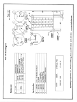
USE AREA AND FOOTING LAYOUT:

312-102 Up/Down Crawl Thru (Port) Page 3 of 3
Rev. 02/20/2020
SportsPlay Equipment, Inc. www.sportsplayinc.com (800) 727-8180
GENERAL ASSEMBLY INSTRUCTIONS:
Check all the parts and hardware with the packing list to be sure you
have received everything needed to assemble this product. Contact your
distributor with notification of any missing or damaged parts. Contact
must be made within ten days of receipt of your order.
GENERAL MAINTENANCE INSTRUCTIONS:
Check MONTHLY for loose bolts, damaged or broken parts. Tighten and/or
replace immediately.
ASSEMBLY AND INSTALLATION:
NOTE:
STEP #1:
STEP #2:
STEP #3:
STEP #4:
STEP #5:
STEP #6:
STEP #7:
STEP #8:
STEP #9:
All threaded ends of bolts protruding beyond nuts must be
cut off and/or peened to eliminate sharp edges. No more
than two threads should extend beyond face of nut.
All washers, “T” nuts, and other fastener hardware used on
round pipe or tubing must be hammered down to conform to the
curved underlying surface to eliminate catch points.
DO NOT tighten nuts more than hand-tight until entire
assembly is completed.
Assemble individual Crawl-Thru units. Drive Plastic Plugs
(355-905) in each end of Rails (303-201).
Rest end of Aluminum Board (603-906) upside-down on two saw
horses. Slide Rings (103-009) onto the board.
Attach rails to Rings. Position end rings equal distance
from each end of board.
Bolt center Angle (313-501) to Aluminum Board (603-906)
with Clips (605-506), lining up Angles with center Rings.
Attach to center Rings.
Bolt end Angles to board with clips, lining up with end
Rings and bottom supports. Supports are positioned between
Angle Brackets & Rings with Rings on outside towards end of
board. Attach bottom supports & Rings to Angle Brackets.
Slip Plastic Caps (535-961) on support ends.
Assemble Leg Support Structure (313-620 & 313-209). Slip
Plastic Caps (315-961) over support (313-209). Attach leg
ends (313-620) to Supports.
Attach individual Crawl-Thru Units to leg support assembly
using T-clamps (415-515) as in STEP #7. Aluminum boards
should meet at center.
Plumb & level. Tighten all nuts & bolts until lock washers
are flat.
/


