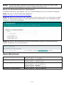
Moxa Technologies ioThinx 4530 Series Quick Install Guide
- Type
- Quick Install Guide
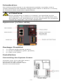
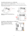
Moxa Technologies ioThinx 4530 Series is an advanced modular controller with a unique hardware and software design that makes it ideal for a variety of industrial data acquisition applications. It features a system power input of 12 to 48 VDC and a field power input of 12/24 VDC. The device is equipped with two RJ45 LAN ports, a 3-in-1 serial interface, and supports either 1 RS-232 port, 1 RS-422 port, or 2 RS-485 ports. Additionally, the ioThinx 4530 Series has field power ground and two ground pins on the back of the device for surge protection.
Moxa Technologies ioThinx 4530 Series is an advanced modular controller with a unique hardware and software design that makes it ideal for a variety of industrial data acquisition applications. It features a system power input of 12 to 48 VDC and a field power input of 12/24 VDC. The device is equipped with two RJ45 LAN ports, a 3-in-1 serial interface, and supports either 1 RS-232 port, 1 RS-422 port, or 2 RS-485 ports. Additionally, the ioThinx 4530 Series has field power ground and two ground pins on the back of the device for surge protection.


-
 1
1
-
 2
2
-
 3
3
-
 4
4
-
 5
5
-
 6
6
-
 7
7
-
 8
8
-
 9
9
-
 10
10


Moxa Technologies ioThinx 4530 Series Quick Install Guide
- Type
- Quick Install Guide
Moxa Technologies ioThinx 4530 Series is an advanced modular controller with a unique hardware and software design that makes it ideal for a variety of industrial data acquisition applications. It features a system power input of 12 to 48 VDC and a field power input of 12/24 VDC. The device is equipped with two RJ45 LAN ports, a 3-in-1 serial interface, and supports either 1 RS-232 port, 1 RS-422 port, or 2 RS-485 ports. Additionally, the ioThinx 4530 Series has field power ground and two ground pins on the back of the device for surge protection.
Ask a question and I''ll find the answer in the document
Finding information in a document is now easier with AI
Related papers
-
Moxa Technologies ioThinx 4500 Series Quick Install Guide
-
 Moxa Technologies DR-120-24 Quick Install Guide
-
Moxa Technologies HDR-60-24 Series Quick Install Guide
-
 Moxa Technologies ioThinx 4530 Series User manual
-
-
Moxa Technologies IOLOGIK E1260 Quick Install Guide
-
Moxa Technologies IOLOGIK E4200 User manual
-
 Moxa Technologies ioLogik 2542-HSPA Quick Install Guide
-
 Moxa Technologies ioPAC 8500-9-RJ45-IEC-T User manual
-
Moxa Technologies MDS-G4012 Series Quick Install Guide


Other documents
-
Moxa ioThinx 4530 Series User manual
-
-
-
-
-
-
-
-
-