Moxa Technologies IOLOGIK E1260 Quick Install Guide

Type
Quick Install Guide
P/N: 1802012001016
*1802012001016*
ioLogik E1200 Series
Quick Installation Guide
Ethernet Remote I/O
Version 6.1, January 2021
Technical Support Contact Information
www.moxa.com/support
2021 Moxa Inc. All rights reserved.
- 2 -
Package Checklist
1 ioLogik E1200 series remote I/O product
Quick installation guide (printed)
Specifications
Input Current ioLogik E1210 Series: 110 mA @ 24 VDC
ioLogik E1211 Series: 200 mA @ 24 VDC
ioLogik E1212 Series: 155 mA @ 24 VDC
ioLogik E1213 Series: 130 mA @ 24 VDC
ioLogik E1214 Series: 188 mA @ 24 VDC
ioLogik E1240 Series: 121 mA @ 24 VDC
ioLogik E1241 Series: 194 mA @ 24 VDC
ioLogik E1242 Series: 139 mA @ 24 VDC
ioLogik E1260 Series: 110 mA @ 24 VDC
ioLogik E1262 Series: 118 mA @ 24 VDC
Input Voltage
12 to 36 VDC
Operating
Temperature
Standard Models: -10 to 60°C (14 to 140°F)
Wide Temp. Models: -40 to 75°C (-40 to 167°F)
Storage Temperature
-40 to 85°C (-40 to 185°F)
Installation
Jumper Settings
Models with DIO, AI, or external power channels require configuring the
jumpers inside the enclosure. Remove the screw located on the back
panel and open the cover to configure the jumpers.
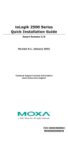
Analog mode configurations are
shown above (Default: Voltage
Mode).
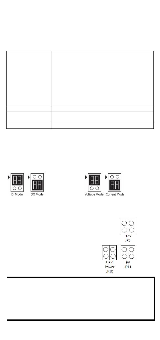
DOs on the ioLogik E1213 have 3
possible external (EXT) power
configurations, which are shown to the
right. Only one field power can be
selected at a time (JP10 / 12V JP5 / 9V
JP11)
and
the jumper must be inserted
vertically, not horizontally
(Default: Field Power JP10).
NOTE
The ioLogik E1213 has 4 pure DO channels and 4 hybrid DIO
channels. For the 4 pure DO channels, you can use the jumpers to
select the power configuration output (i.e., field power, 12 V, 9
V). But for the 4 hybrid DIO channels, you cannot use the
jumpers to select th
e power configuration output. Instead, you
can only use the jumpers to set the DIO channels to either DI
mode or DO mode.
- 3 -
I/O Wiring
Digital Inputs/Outputs
Analog Inputs/Outputs
Relay Output (Form A)
RTD Inputs
- 4 -
TC Inputs
NOTE
A “load” in a circuit schematic is a component or portion of the
circuit that consumes electric power. For the diagrams shown in
this document, “load” refers to the devices or systems connected
to the remote I/O unit.
Mounting
There are two sliders on the back of the unit for DIN rail and wall
mounting.
1. Mounting on a DIN rail: Pull out the bottom slider; latch the unit
onto the DIN-rail, and push the slider back in.
2. Mounting on the wall: Pull out both the top and bottom sliders and
align the screws accordingly.
Connecting the Power
Connect the +12 to +36 VDC power line to the ioLogik E1200s terminal
block V+ terminal; connect the ground from the power supply to the V-
terminal. Connect the ground pin ( ) if earth ground is available.
NOTE
For safety reasons, wires connecting the power supply should be
at least 2 mm in diameter (e.g., 12 gauge wires).
Connecting to the Network
The ioLogik E1200 has two built-in RJ45 Ethernet ports for connecting
standard direct or cross-over Ethernet cables.
- 5 -
LED Indicators
Type
Color
Description
Power
Amber
System power is ON
Off
System power is OFF
Ready
Green
System is ready
Flashing
Flashes every 1 sec when the Locate
function is triggered
Flashing Flashes every 0.5 sec when the firmware is
being upgraded
Flashing
An on/off period cycle: 0.5 second shows
Safe Mode
Off
System is not ready.
Port 1
Green
Ethernet connection enabled
Flashing
Transmitting or receiving data
Port 2
Green
Ethernet connection enabled
Flashing
Transmitting or receiving data
EXT
(E1213 only)
Green
EXT field power input is connected
Off
EXT field power input is disconnected
System Configuration
Configuration via Web Console
Main configuration of an ioLogik E1200 is by web console.
Default IP Address: 192.168.127.254
Subnet Mask: 255.255.255.0
NOTE
Be sure to configure the host PC’s IP address to the same subnet
as the ioLogik E1200. For example, 192.168.127.253
ioSearch Utility
ioSearch is a search utility that helps users locate an ioLogik E1200 on the
local network. The utility can be downloaded from Moxa’s website.
Load Factory Default Settings
There are three ways to restore the ioLogik E1200 to factory default
settings.
1. Hold the RESET button for 5 seconds.
2. In the ioSearch utility, right-click on the ioLogik device to be reset and
select Reset to Default.
3. Select Load Factory Default from the web console.
NOTE
Please refer to the user's manual for detailed configuration and
settings information.
- 6 -
How to Download the Software
Step 1: Click on the following link to open the Support & Downloads
search tool:
http://www.moxa.com/support/support_home.aspx?isSearchShow=1
Step 2: Type the model name in the search box or select a product from
the drop down box and then click Search.
Step 3: Click the Software Packages link to download the latest
software for the product.
ATEX Information
1. Certificate number: DEMKO 13 ATEX 1210600X
2. Certification string: Ex nA nC IIC T3 Gc
3. Standards covered:
EN 60079-0:2012+A11:2013, EN 60079-15:2010
4. These products are to be installed in an ATEX Certified IP54
enclosure and accessible only by the use of a tool.
5. These products are for use in an area of not more than pollution
degree 2 in accordance with IEC 60664-1.
  • Page 1 1
  • Page 2 2
  • Page 3 3
  • Page 4 4
  • Page 5 5
  • Page 6 6

Moxa Technologies IOLOGIK E1260 Quick Install Guide

Type
Quick Install Guide

Ask a question and I''ll find the answer in the document

Finding information in a document is now easier with AI