Scotsman FME804R User manual
- Category
- Ice cube makers
- Type
- User manual
This manual is also suitable for

INTRODUCTION
To the owner or user: The service manual you are
reading is intended to provide you, and the
maintenance or service technician, with the
information needed to install, start up, clean,
maintain, and service this ice system.
The FME804R and NME654R are a remote
condenser modular ice systems that fit a variety of
Scotsman storage bins. Their features include:
front service for the freezer, gearmotor, control
box, water reservoir, and bin control; an electronic
control (AutoSentry) for monitoring ice and water
level; a thermostatic expansion valve; and HP62 as
the refrigerant.
NME654R & FME804R
January 2000
Page 1
Table of Contents
FOR THE INSTALLER · · · · · · · · · · · · · · · · · · · · · · · · · · · · · · · · · · · · · · Page 2
FOR THE INSTALLER · · · · · · · · · · · · · · · · · · · · · · · · · · · · · · · · · · · · · · Page 3
REMOTE CONDENSER SPECIFICATIONS · · · · · · · · · · · · · · · · · · · · · · · · · · · Page 4
Remote Condenser Location · · · · · · · · · · · · · · · · · · · · · · · · · · · · · · · · · · · Page 5
FOR THE INSTALLER: Remote Condenser · · · · · · · · · · · · · · · · · · · · · · · · · · · Page 6
FOR THE INSTALLER: Coupling Instructions · · · · · · · · · · · · · · · · · · · · · · · · · · Page 7
FOR THE INSTALLER: Location · · · · · · · · · · · · · · · · · · · · · · · · · · · · · · · · · Page 8
FOR THE PLUMBER · · · · · · · · · · · · · · · · · · · · · · · · · · · · · · · · · · · · · · · Page 9
FOR THE ELECTRICIAN · · · · · · · · · · · · · · · · · · · · · · · · · · · · · · · · · · · · · Page 10
FOR THE INSTALLER: Completed Installation · · · · · · · · · · · · · · · · · · · · · · · · · · Page 11
FOR THE INSTALLER: Final Check List · · · · · · · · · · · · · · · · · · · · · · · · · · · · · Page 12
START UP · · · · · · · · · · · · · · · · · · · · · · · · · · · · · · · · · · · · · · · · · · · · Page 13
COMPONENT DESCRIPTION · · · · · · · · · · · · · · · · · · · · · · · · · · · · · · · · · · Page 14
COMPONENT DESCRIPTION: Control Box · · · · · · · · · · · · · · · · · · · · · · · · · · · Page 15
ELECTRICAL SEQUENCE · · · · · · · · · · · · · · · · · · · · · · · · · · · · · · · · · · · · Page 16
OPERATION: Water · · · · · · · · · · · · · · · · · · · · · · · · · · · · · · · · · · · · · · · Page 17
OPERATION: Refrigeration · · · · · · · · · · · · · · · · · · · · · · · · · · · · · · · · · · · · Page 18
OPERATION: Refrigeration · · · · · · · · · · · · · · · · · · · · · · · · · · · · · · · · · · · · Page 19
OPERATION: Refrigeration · · · · · · · · · · · · · · · · · · · · · · · · · · · · · · · · · · · · Page 20
CLEANING & SANITIZING · · · · · · · · · · · · · · · · · · · · · · · · · · · · · · · · · · · · Page 21
SENSOR MAINTENANCE · · · · · · · · · · · · · · · · · · · · · · · · · · · · · · · · · · · · Page 22
BEARING MAINTENANCE · · · · · · · · · · · · · · · · · · · · · · · · · · · · · · · · · · · · Page 23
AUGER AND OTHER MAINTENANCE · · · · · · · · · · · · · · · · · · · · · · · · · · · · · Page 24
OPERATING CHARACTERISTICS · · · · · · · · · · · · · · · · · · · · · · · · · · · · · · · Page 25
SERVICE DIAGNOSIS: · · · · · · · · · · · · · · · · · · · · · · · · · · · · · · · · · · · · · Page 26
SERVICE DIAGNOSIS: · · · · · · · · · · · · · · · · · · · · · · · · · · · · · · · · · · · · · Page 27
CONTROL SYSTEM DIAGNOSTICS · · · · · · · · · · · · · · · · · · · · · · · · · · · · · · Page 28
REMOVAL AND REPLACEMENT: Water Reservoir & Bin Controls · · · · · · · · · · · · · · · Page 29
REMOVAL AND REPLACEMENT: Bearing And Breaker · · · · · · · · · · · · · · · · · · · · Page 30
REMOVAL AND REPLACEMENT: Auger · · · · · · · · · · · · · · · · · · · · · · · · · · · · Page 31
REMOVAL AND REPLACEMENT: Water Seal · · · · · · · · · · · · · · · · · · · · · · · · · · Page 32
REMOVAL AND REPLACEMENT: Evaporator · · · · · · · · · · · · · · · · · · · · · · · · · · Page 33
REMOVAL AND REPLACEMENT: Gearmotor Assembly · · · · · · · · · · · · · · · · · · · · Page 34
REFRIGERATION SERVICE · · · · · · · · · · · · · · · · · · · · · · · · · · · · · · · · · · · Page 35
Note this symbol when it appears.
It is an alert for important safety
information on a potential hazard.

FOR THE INSTALLER
These machines are designed to fit the
following Scotsman storage bins:
·
SB480 and extensions (with bin top
KBT18)
·
HTB555 or BH550 using bin top
KBT14 or KBT20
·
BH800 using bin top KBT15 (one
unit) or KBT25 (two units).
·
BH801 using bin top KBT28
·
BH900 using bin top KBT24
NME654 Dispenser Applications
The NME654 can be placed on and
used with certain ice and ice-beverage
dispensers. Kits are required for proper
operation, see the following list:
·
ID150, use adapter KBT42 and
KNUGDIV
·
ID200 or ID250, use adapter KBT46
and KDIL-N-ID2
·
Cornelius ED/DF200 beverage
dispensers, use KBT46 and
KDIL-N-200
·
Cornelius ED/DF250 beverage
dispensers, use KBT46 and
KDIL-N-250
·
Lancer nugget ice & beverage
dispenser, use KDIL-N-L and Lancer
kit #82-3491.
NME654R & FME804R
May 2006
Page 2
Model Dimensions
W"xD"xH"
Basic
Electrical
Ice Type Refrigerant
Type
Refrigerant
Charge
Min Circuit
Ampacity
Max Fuse
Size
FME804RS-1A 21" x 24" x 27" 115/60/1 FLAKE R-404A 208 ounces 22.5 30
NME654RS-1A same same Nugget R-404A same same same
* Minimum Circuit Ampacity is used to determine wire size and type per National Electric Code.
SPECIFICATIONS: ICE MACHINE

FOR THE INSTALLER
Installation Limitations:
This ice system is designed to be installed indoors,
in a controlled environment:
Min. Max.
Air Temperature 50
0
F 100
0
F
(Not including the remote condenser)
Water Temperature 40
0
F 100
0
F
Water Pressure (psi) 20 80
Voltage -5% +10%
(Compared to the nameplate)
Operating the machine outside of the limitations is
misuse and can void the warranty.
Scotsman Ice Systems are designed and
manufactured with the highest regard for safety
and performance. They meet or exceed the
standards of UL, NSF, and CUL.
Scotsman assumes no liability or responsibility of
any kind for products manufactured by Scotsman
that have been altered in any way, including the
use of any part and/or other components not
specifically approved by Scotsman.
Scotsman reserves the right to make design
changes and/or improvements at any time.
Specifications and design are subject to change
without notice.
Location
After uncrating and inspection, the unit is ready for
installation. It is important that the machine be
installed in a location where it has enough space
around it to be accessible for service, usually a
minimum of 6 inches. Try to avoid hot, dirty and
crowded locations. Be sure that the location for the
machine is within the limitations described.
Storage Bin
Tip the storage bin on its back, using parts of the
carton to protect the exterior finish. Install the legs
into the threaded holes in the bottom of the bin.
Turn the leg levelers all the way in preparation for
leveling later. Return the bin to the upright position,
remove paper covering the bin gasket.
Install the bin top according to the directions with
the bin top.
Note: Do not push bin into position, but lift it there.
Pushing a bin, especially one with ice in it, can
cause damage to the legs and the leg mounts.
Ice Maker
The machine is heavy, so the use of a mechanical
lift is recommended for lifting the machine high
enough to install on top of the bin. After the unit is
placed on the bin, line it up so it is even with the
back side. Secure the machine to the bin with the
hardware provided with the machine.
Remove the front panel and remove any shipping
blocks.
Note: Be sure to allow a 6" minimum space
above the top of the machine for service.
NME654R & FME804R
January 2000
Page 3

NME654R & FME804R
January 2000
Page 4
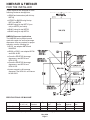
REMOTE CONDENSER SPECIFICATIONS
RTE25 Precharged line set, 25’, R-404A
RTE40. Precharged line set, 40’, R-404A
ICEMAKER NAMEPLATE
LOCATED ON BACK PANEL
SERIAL PLATE LOCATED
Adjustable Roof Clearance
12.00 18.00 24.00
30.48 45.72 60.95
Discharge Line
.50 Quick Connect Fitting
1.27
Liquid Line
.38 Quick Connect Fitting
.95
.53
1.35
(6
)
Air Intake
Air Discharge
14.53
2.75
19.75
50.17
2.00
5.08
2.07
19
7
8
"
23
13
16
"
Model Use with Basic Electrical
ERC101-1 1 FME804R or 1 NME654R 115/60/1
ERC DIMENSIONS
Model A B F G
ERC101 33
3
8
"10
3
4
"16
3
4
"11
5
8
"

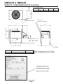
Remote Condenser Location
Use the following for planning the placement of
the condenser relative to the ice machine
Location Limits - condenser location must not
exceed ANY of the following limits:
·
Maximum rise from the ice machine to the
condenser is 35 physical feet
·
Maximum drop from the ice machine to the
condenser is 15 physical feet
·
Physical line set maximum length is 100 feet.
·
Calculated line set length maximum is 150.
Calculation Formula:
·
Drop = dd x 6.6 (dd = distance in feet)
·
Rise = rd x 1.7 (rd = distance in feet)
·
Horizontal Run = hd x 1 (hd = distance in feet)
·
Calculation: Drop(s) + Rise(s) + Horizontal Run
= dd+rd+hd = Calculated Line Length
Configurations that do NOT meet these
requirements must receive prior written
authorization from Scotsman.
Do NOT:
·
Route a line set that rises, then falls, then rises.
·
Route a line set that falls, then rises, then falls.
Calculation Example 1:
The condenser is to be located 5 feet below the ice
machine and then 20 feet away horizontally.
5 feet x 6.6 = 33. 33 + 20 = 53. This location would
be acceptable
Calculation Example 2:
The condenser is to be located 35 feet above and
then 100 feet away horizontally.
35 x 1.7 = 59.5. 59.5 +100 = 159.5. 159.5 is
greater than the 150 maximum and is NOT
acceptable.
NME654R & FME804R
January 2000
Page 5
22.87"
17.15"
40.35"
hd
rd
dd
Remote
Condenser
Located ABOVE
Ice Machine
Remote
Condenser
Located BELOW
Ice Machine
Condenser Distance and
Location Schematic

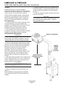
FOR THE INSTALLER: Remote Condenser
Location
Limited to a 40 foot or a 25 foot length of
precharged refrigerant tubing connecting the ice
machine to the remote condenser. The condenser
must be above or level with the ice machine.
Select the best available location, protecting the
condenser from extremes of dirt, dust, and sun.
Meet all applicable building codes. Usually the
services of a licensed electrician are required.
Roof Attachment
1. Install and attach the remote condenser to the
roof of the building, using the methods and
practices of construction that conform to the local
building codes, including having a roofing
contractor secure the condenser to the roof.
2. Have an electrician connect the remote
condenser fan motor to the ice machine, using the
junction box at the back of the ice machine.
PRECHARGED LINE ROUTING
CAUTION
Do not connect precharged tubing until all routing
and forming of the tubing is complete. See the
coupling instructions for connecting information.
1. Each set of precharged refrigerant lines (either
25 foot or 40 foot) consists of a 3/8 inch diameter
liquid line and a 1/2 inch diameter discharge line.
Both ends of each line have quick connect
couplings, one end has a schrader valve
connection, that end goes to the condenser.
Note: The openings in the building ceiling or wall,
listed in the next step, are the minimum sizes
recommended for passing the refrigerant lines
through.
2. Have the roofing contractor cut a minimum hole
for the refrigerant lines of 1 3/4 inch. Check local
codes, a separate hole may be required for the
electrical power to the condenser.
CAUTION
DO NOT KINK OR CRIMP REFRIGERANT
TUBING WHEN INSTALLING IT.
3. Route the refrigerant lines through the roof
opening.
Follow straight line routing whenever possible.
Any excess tubing MUST be retained within the
building.
4. Spiral the excess length of pre charged tubing
inside the building. Use a horizontal spiral (need
not be as tight as illustrated) to avoid any traps in
the lines.
5. Have the roofing contractor seal the holes in the
roof per local codes.
CAUTION
The couplings on the sets of precharged lines are
self sealing when installed properly. Carefully
follow the instructions:
NME654R & FME804R
January 2000
Page 6
REMOTE CONDENSER
LOCATE REMOTE
CONDENSER ABOVE
ICEMAKER
SPIRAL
EXCESS
TUBING
INSIDE
BUILDING

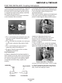
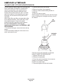
Initial Connections:
1. Remove the protector caps and plugs. Wipe the
seats and threaded surfaces with a clean cloth to
be certain that no foreign matter remains on them.
2. Lubricate the inside of the couplings, especially
the O-Rings with refrigerant oil.
3. Position the fittings on the correct connections
on the condenser and ice machine.
·
The ½ inch discharge line (schrader valve end)
goes to the remote condenser fitting marked
“discharge line.”
·
The
3
8
inch liquid line (schrader valve end) goes
to the remote condenser fitting marked “liquid
line.”
·
The ½ inch discharge line goes to the ice
maker fitting marked “discharge line.”
·
The
3
8
inch liquid line goes to the ice maker
fitting marked “liquid line.”
Final Connections:
4a. Begin by tightening the couplings together by
hand. Continue to turn the swivel nuts by hand until
is is certain that the threads are properly engaged.
4b. Using two wrenches, one to rotate the swivel
nut and one to hold the tubing, tighten each
coupling.
It is CRITICAL that ONLY the NUT on the
pre-charged tube be turned or the diaphragms will
be torn loose by the piercing knives and be loose
in the refrigeration system causing severe
operational problems.
Note: As the coupling is tightened, the diaphragms
in the quick connect couplings will begin to be
pierced. As that happens, there will be increased
resistance to tightening the swivel nut.
4c. Continue tightening the swivel nut until it
bottoms out or a very definite increase in
resistance is felt (no threads should be showing).
Do NOT overtighten.
5. Using a marker or pen, mark a line lengthwise
from the coupling union nut to the bulkhead. Then
tighten the coupling and additional 1/4 turn. As the
nut turns, the line will show when 1/4 turn is made.
6. After all connections are made, and after the
king valve has been opened (do not open at this
time), check the couplings for leaks.
NME654R & FME804R
January 2000
Page 7
FOR THE INSTALLER: Coupling Instructions
SCHRADER
NO SCHRADER
TO REMOTE
TO ICEMAKER
Clean and Lubricate Couplings
Tighten Swivel Nut
Rotate Swivel Nut ¼ Turn More

NME654R & FME804R
January 2000
Page 8
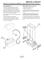
FOR THE INSTALLER: Location
TYPICAL INSTALLATION
REMOTE
CONDENSER
EXCESS
PRECHARGED
TUBING INSIDE
BUILDING
Ice Machine
SERVICE
ACCESS
SERVICE ACCESS
SIDE AND BACK
ROOF
CUTAWAY
WALL
CUTAWAY

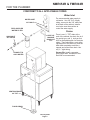
FOR THE PLUMBER
CONFORM TO ALL APPLICABLE CODES
Water Inlet
The recommended water supply is
cold water. Use 3/8" O.D. copper
tubing, connect to the 3/8" male flare
at the back of the cabinet. Install a
hand valve near the machine to
control the water supply.
Drains
There is one ¾ " FPT drain at the
back of the cabinet, the drain line is of
the gravity type, and ¼ inch per foot
fall is an acceptable pitch for the drain
tubing. There should be a vent at the
highest point of the drain line, and the
ideal drain receptacle would be a
trapped and vented floor drain. Use
only ¾ " rigid tubing.
Storage Bin: Install a separate
gravity type drain. Insulation of this
drain line is recommended.
NME654R & FME804R
January 2000
Page 9
FLOOR DRAIN
VENT BIN DRAIN
3/4" FPT
VENT ICE
MACHINE
DRAIN, 3/4"
FPT
WATER INLET
3/8" MALE
FIELD SUPPLIED
WATER FILTER
HAND SHUT
OFF VALVE
CONNECT TO
COLD WATER

FOR THE ELECTRICIAN
CONFORM TO ALL APPLICABLE CODES
Connect the electrical power to the unit to the wires
in the junction box at the rear of the machine.
Check the nameplate (located on the back panel)
for the voltage requirements, and for the minimum
circuit ampacity. The machine requires a solid
chassis to earth ground wire.
Connect the ice machine to its own electrical circuit
so it is individually fused. Voltage variation must
remain within design limitations, even under
starting conditions.
There is a separate junction box for the remote
condenser fan motor.
Install an interconnecting wire between the remote
condenser and the junction box at the back of the
ice machine.
The remote condenser must be wired to the ice
machine in accordance with local and national
electrical codes with a minimum of 18 Awg. wire
with an ground bonding wire connected to the
ground screws provided in both the condenser and
machine field wiring boxes. All outdoor wiring must
be in rainproof conduit.
All external wiring must conform to national,
state, and local electrical codes. The use of a
licensed electrician is required to perform the
electrical installation.
NME654R & FME804R
January 2000
Page 10
TERMINAL STRIP
FOR REMOTE
CONDENSER
ICE MACHINE
JUNCTION BOX
POWER
SUPPLY
GROUND
THE
CHASSIS
RAIN PROOF
CONDUIT

NME654R & FME804R
January 2000
Page 11
FOR THE INSTALLER: Completed Installation
ROOF
CUT-AWAY
INSULATED
PRECHARGED
REFRIGERANT
TUBING
A typical installation should generally appear as
illustrated below. The remote condenser must be
located above the ice machine and the precharged
lines installed per the instructions on page 6.

FOR THE INSTALLER: Final Check List
1. Is the ice system installed
indoors in a location where the air
and water temperatures are
controlled, and where they do not
exceed the design limitations?
2. Is there an electrical service
disconnect within sight of the
installed machine? Has the
voltage been checked, and
compared to nameplate
requirements?
3. Have all the plumbing
connections been made and
checked for leaks?
4. Has the machine and bin been
leveled?
5. Is there a minimum of 6"
clearance at the rear, left, and
right of the machine for proper
service access and air
circulation?
6. Is the water pressure a
minimum of 20 PSI?
7. Has the machine been secured
to the bin?
8. If two units on one condenser,
has the relay kit been installed?
9. Is there a water shut off valve
installed near the machine?
10. Is the remote condenser
installed per local building codes,
and in a place where it has
adequate ventilation and minimal
solar heat gain?
11. Has all shipping material and
literature (inside the front panel)
been removed from the units?
12. Have the remote condenser
and precharged lines been
properly installed?
13. Has the electrical connection
between the icemaker and the
condenser been made?
14. Verify that the master switch
is in the OFF position.
15. Switch on the electrical power.
16. Refer to Pre-Start instructions, the next page.
NME654R & FME804R
January 2000
Page 12
ROOF
HOLES
SEALED?
POWER
SUPPLY?
LEVELED?
PLUMBING?
REMOTE
CONDENSER
SECURED?

INITIAL START UP
Pre-Start Inspection
1. Remove the front, left, and right side service
panels.
2. Check that any styrofoam shipping blocks have
been removed.
3. Inspect the interior of the machine for loose
screws or wires. Check that no refrigerant lines
are rubbing each other. Check that the fan blade
turns freely (remote condenser).
4. Check that the refrigerant lines are properly
installed.
5. Check that the electrical power has been on for
at least 4 hours.
6. Check that the unit is installed correctly
according to the final check list on page 11.
Start Up
1. Go through the pre-start inspection.
2. Open the hand valve, observe that water enters
the water reservoir, fills the tube from the reservoir
to the evaporator, and then shuts off. Check for
leaks.
3. Open the King Valve.
4. Turn the master switch on.
The electrical start up sequence is automatic.
A. There should be a short (15 second) delay
before the gearmotor starts.
B. After the gearmotor starts, the liquid line valve
will open, the low pressure control will close and
the compressor will start.
5. The remote condenser fan turns, and the
condenser begins to discharge warm air.
6. The unit should soon be making ice, if desired
the low side pressure can be checked, it should be
30 PSIG + or - 4 PSIG. The discharge pressure will
depend upon air and water temperatures, but
should be between 180 PSIG and 300 PSIG.
7. THERE ARE NO ADJUSTMENTS TO MAKE,
so replace the panels.
8. Clean and/or sanitize the storage bin interior,
wipe off the exterior with a clean, damp cloth.
9 Give the owner/user the service manual, instruct
him/her in the operation of the unit, and make sure
they know who to call for service.
10. Fill out the manufacturers registration and mail
it to Scotsman.
NME654R & FME804R
January 2000
Page 13

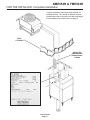
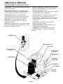
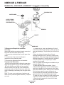
COMPONENT DESCRIPTION
Control Box: Contains the electrical controls that
operate the machine.
High Pressure Cut Out: An automatic reset
switch sensing the high side refrigeration pressure.
It is set to shut the machine off at 450 PSIG.
Pump Down Control: An automatic reset
pressure switch connected to the low side of the
refrigeration system. Controls the compressor.
Evaporator: A vertical stainless steel tube,
refrigerated, and water filled. In it, there is a
stainless steel auger.
Reservoir: Float operated, it maintains the water
level in the evaporator at a constant level, it also
contains the water level sensor.
Water Level Sensor: Senses if there is water in
the reservoir to make ice out of. Will shut the
machine off it there is none.
Ice Discharge Chute: Directs the ice produced by
the evaporator into the storage bin.
Ice Level Sensor: An electronic “eye”, it senses
the presence of ice in the bottom of the ice
discharge chute. Operates to turn the ice machine
on and off automatically as the level of ice in the
bin changes.
Gear Motor: An oil filled, speed reduction
gearbox, driving the auger.
Cleaning Drain Tube: When uncapped and
lowered, drains the evaporator.
Compressor: The refrigerant vapor pump.
Expansion valve: The refrigerant metering
device.
NME654R & FME804R
January 2000
Page 14
CONTROL BOX
EXPANSION VALVE
WATER LEVEL
SENSOR
RESERVOIR
CLEANING
DRAIN TUBE
EVAPORATOR
GEAR MOTOR
ICE LEVEL
SENSOR
HIGH PRESSURE
CUT OUT
COMPRESSOR
ICE CHUTE

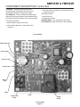
COMPONENT DESCRIPTION: Control Box
Contactor: A definite purpose contactor
connecting the compressor and the remote
condenser fan motor to the power supply.
Circuit Board: The circuit board receives input
signals from several sensors and translates them
to control the electrical power to the various loads.
The sensors include:
·
Photo-electric eyes for bin level
·
Conductivity probe for water level in the
reservoir
·
Current meter to measure the amp draw of the
auger drive motor
The loads include:
·
Liquid line coil
·
Auger drive motor
Potential Relay: The compressor start relay.
On/Off Switch: Manual control for the machine.
NME654R & FME804R
January 2000
Page 15
LED3
LED1
Power Light
Control Board
Auger
Relay
Compressor
Relay
Freeze Light
Bin Full
Light
Water OK Light
Service Light

There are 7 indicator lights on the control board:
·
WTR-OK (Water OK). Green. Normal =
Glowing. Glows when there is water in the
reservoir.
·
PWR-OK (Power OK). Green. Normal =
Glowing. Glows when the control board has
power and is functional.
·
Service. Red. Normally Off.
·
Freeze. Red. Normally glowing when making
ice.
·
Bin Full. Red. Normally Off when making ice.
·
LED1. White. Located next to the board’s
Compressor Relay. Normally Glowing when
making ice.
·
LED3. White. Located next to the board’s Auger
Motor Relay. Normally Glowing when making
ice.
If the machine is switched off at the mode switch,
but is otherwise ready to go, switching the mode
switch to ON does the following:
·
The PWR-OK light glows.
· If there is water in the reservoir the WTR-OK
light glows.
·
After 10 seconds the Freeze, LED1 and LED3
lights glow and the machine starts up.
Start Up:
·
The compressor relay and auger motor relay
become energized, connecting power to the
windings of the auger motor and liquid line valve
coil.
·
The liquid line valve opens, refrigerant flows to
the expansion valve.
·
The pump down pressure switch closes
connecting power to the contactor coil
·
The contactor is energized, connecting power to
the compressor, and the compressor starts.
·
As ice is made it passes between the ice level
sensors but because it is not a continuous
stream it only interupts the sensor’s infrared
beam momentarily. The bin full light remains off
and the machine stays on until ice builds up in
the bin and blocks the path between the
sensors for 6 seconds or longer. When that
occurs the bin full light glows and the machine
shuts down.
Shut Down:
·
The compressor relay opens, LED1 goes out.
·
The liquid line valve closes, stopping refrigerant
flow.
·
The pump down control opens after the suction
pressure falls to its cut out point.
·
The compressor contactor opens
·
The compressor stops
·
The auger motor stays on for 1 more minute,
clearing out ice in the evaporator, and then
·
The auger motor relay opens, LED3 goes out
and the auger motor stops.
The liquid line valve will not reopen until 2 minutes
or more have passed after the last shut down.
If the path between the ice level sensors remains
clear for more than 10 seconds the ice machine
will restart.
Control Board Protection Devices
·
When the water level in the reservoir falls
below the water level sensor’s tip, the WTR-OK
light goes out and the machine shuts down.
When water refills the reservoir the WTR-OK
light glows and the machine starts up again.
·
If the auger drive motor current becomes
excessive the liquid line valve and auger drive
motor will be switched Off and the Service light
will blink. The control board will restart the auger
drive motor in 4 minutes. If during the first 60
seconds after restart the auger motor current
stays within limits, the liquid line valve is
reopened and the machine returns to normal
operation. If the auger motor’s current is
excessive within 60 seconds after the restart,
the process will be repeated once more. If
during that try the current is still excessive the
machine shuts down and must be manually
reset. The service light will then be glowing
continuously.
To Reset: Disconnect and reconnect power to
the ice machine.
Other Protection Devices:
·
If the high pressure cut out switch opens the
machine will stop immediately. It will
automatically reset when the pressure falls
below its cut in point.
The mode (on - off) switch is the manual control
for the complete machine, but it is not a service
disconnect.e, but it is not a service disconnect.
NME654R & FME804R
January 2000
Page 16
ELECTRICAL SEQUENCE

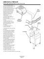
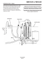
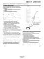
OPERATION: Water
Water enters the machine through the 3/8" male
flare at the rear of the cabinet, goes to the water
reservoir which it enters through the float valve.
The water them goes out the bottom of the
reservoir tank to the bottom of the evaporator.
Reservoir overflow or evaporator condensation is
routed to the drain.
NME654R & FME804R
January 2000
Page 17
RESERVOIR
DRAIN TUBE
WATER LEVEL
WATER
INLET
DRAIN
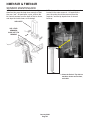
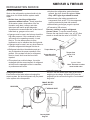
Water Level: The correct water level should be
checked when the machine is making ice. Locate the
water level in the reservoir and compare it to the
horizontal line molded into the side of the reservoir.
The correct level should be between
1
8
" above and
1
4
"
below the line. If needed, bend the float arm up or
down to adjust the water level.

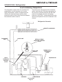
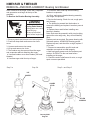
OPERATION: Refrigeration
Beginning at the compressor, the refrigerant is
compressed into a high temperature gas. The
discharge line directs this gas to the condenser. At
the remote condenser the gas is cooled by air and
condenses into a liquid. This high pressure liquid
then goes through the liquid line to the head
pressure control valve, into the receiver, through
the liquid line valve and then through the
expansion valve.
The thermostatic expansion valve meters liquid
refrigerant into the evaporator, the volume of liquid
refrigerant depending upon the temperature of the
evaporator; warmer evaporators get more
refrigerant and colder evaporators get less. At the
evaporator, the refrigerant enters an area of
relatively low pressure, where it can easily “boil off”
or evaporate. As it evaporates, it absorbs heat
from the evaporator and whatever is in contact with
it (such as the water inside it). After the
evaporator, the refrigerant, now a low pressure
vapor, goes through the suction line back to
compressor, where the cycle is repeated.
NME654R & FME804R
January 2000
Page 18
DETAIL OF HEAD
PRESSURE CONTROL
VALVE
DISCHARGE
LINE
LIQUID LINE
HEAD
PRESSURE
CONTROL
VALVE
RECEIVER
COMPRESSOR
Refrigeration Schematic
KING
VALVE
SUCTION
LINE
THERMOSTATIC
EXPANSION
VALVE
LIQUID LINE
VALVE
REMOTE CONDENSER
EVAPORATOR

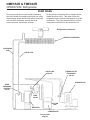
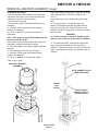
OPERATION: Refrigeration
Low Condensing Temperature
The refrigeration system under low condenser air
temperatures is much the same as it is under
higher temperatures, with the exception that the
resulting low head pressures cause the head
pressure control to close off the liquid line between
the condenser and the receiver.
This forces more refrigerant into the condenser
(with a small amount of discharge gas going into
the receiver to maintain pressure until the head
pressure is built back up to the rated gauge
pressure of 180 PSIG). At that pressure the valve
opens up the liquid line from the condenser to the
receiver.
NME654R & FME804R
January 2000
Page 19
LIQUID LINE
VALVE
THERMOSTATIC
EXPANSION
VALVE
SUCTION
LINE
KING
VALVE
Refrigeration Schematic
COMPRESSOR
RECEIVER
HEAD
PRESSURE
CONTROL
VALVE
LIQUID LINE
DISCHARGE
LINE
DETAIL OF HEAD
PRESSURE CONTROL
VALVE
REMOTE CONDENSER
EVAPORATOR

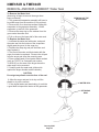
OPERATION: Refrigeration
PUMP DOWN
During the pump down cycle (usually initiated by
the circuit board de-energizing the liquid line valve)
the discharge gases flow through their normal path
to the remote condenser, through the head
pressure control, and into the receiver.
At this point the refrigerant flow is stopped by the
closed liquid line valve. This action forces the
refrigerant into the receiver and keeps it out of the
compressor. The pump down continues until the
low pressure control turns the compressor off.
NME654R & FME804R
January 2000
Page 20
DISCHARGE
LINE
LIQUID LINE
HEAD
PRESSURE
CONTROL
VALVE
RECEIVER
COMPRESSOR
Refrigeration Schematic
KING
VALVE
SUCTION
LINE
LIQUID LINE
VALVE
REMOTE CONDENSER
THERMOSTATIC
EXPANSION
VALVE
EVAPORATOR
Page is loading ...
Page is loading ...
Page is loading ...
Page is loading ...
Page is loading ...
Page is loading ...
Page is loading ...
Page is loading ...
Page is loading ...
Page is loading ...
Page is loading ...
Page is loading ...
Page is loading ...
Page is loading ...
Page is loading ...
-
 1
1
-
 2
2
-
 3
3
-
 4
4
-
 5
5
-
 6
6
-
 7
7
-
 8
8
-
 9
9
-
 10
10
-
 11
11
-
 12
12
-
 13
13
-
 14
14
-
 15
15
-
 16
16
-
 17
17
-
 18
18
-
 19
19
-
 20
20
-
 21
21
-
 22
22
-
 23
23
-
 24
24
-
 25
25
-
 26
26
-
 27
27
-
 28
28
-
 29
29
-
 30
30
-
 31
31
-
 32
32
-
 33
33
-
 34
34
-
 35
35


Scotsman FME804R User manual
- Category
- Ice cube makers
- Type
- User manual
- This manual is also suitable for
Ask a question and I''ll find the answer in the document
Finding information in a document is now easier with AI
Related papers
-
Scotsman KBT37-2X -17-3286-01 Operating instructions
-
-
-
-
-
-
-
Scotsman FME1200RL User manual
-
-
Other documents
-
Dometic Freeze Control Hang Tag For Air Conditioner Installation guide
-
Ice-O-Matic MFI2406 User manual
-
GE ZPK1 Installation guide
-
Middleby 20048SB Specification
-
Scotsman Ice Ice Machine User manual
-
 Cornelius Series 200 Installation guide
-
Cornelius UCR 700 Series User manual
-
Cornelius WCC1401-A Series User manual
-
 IMI Cornelius, Inc. 200 Installation guide
-
Middleby 20108RSB Operating instructions

