Page is loading ...

Table of Contents
Cover photo may show optional equipment not supplied
with standard unit.
For an Operator’s Manual and Decal Kit in French
Language, please see your Land Pride dealer.
Read the Operator’s Manual entirely. When you see this symbol,
the subsequent instructions and warnings are serious - follow
without exception. Your life and the lives of others depend on it!
!
Hydraulic Post Hole Diggers
HD25 and HD35
317-076M
Operator’s Manual
Printed 10/16/19
35989
Front Loader Mount for Tractors Skid Steer Mount for Skid Steers
3-Point Mount
35975
35974
Center Mounting Bracket
Offset Mounting Bracket
35975
18974
Bucket Mount
Offset Mounting Bracket

10/16/19HD25 and HD35 Hydraulic Post Hole Diggers 317-076M
Machine Identification
Record your machine details in the log below. If you replace this manual, be sure to transfer this information to the new
manual.
If you, or the dealer, have added Options not originally ordered with the machine, or removed Options that were
originally ordered, the weights and measurements are no longer accurate for your machine. Update the record by
adding the machine weight and measurements provided in the Specifications & Capacities Section of this manual with
the Option(s) weight and measurements.
Dealer Contact Information
Model Number
Serial Number
Machine Height
Machine Length
Machine Width
Machine Weight
Delivery Date
First Operation
Accessories
Name:
Street:
City/State:
Telephone:
Email:
WARNING: Cancer and reproductive harm - www.P65Warnings.ca.gov
!
California Proposition 65

Table of Contents
© Copyright 2019 All rights Reserved
Land Pride provides this publication “as is” without warranty of any kind, either expressed or implied. While every precaution has been taken in the
preparation of this manual, Land Pride assumes no responsibility for errors or omissions. Neither is any liability assumed for damages resulting from the use
of the information contained herein. Land Pride reserves the right to revise and improve its products as it sees fit. This publication describes the state of this
product at the time of its publication, and may not reflect the product in the future.
Land Pride is a registered trademark.
All other brands and product names are trademarks or registered trademarks of their respective holders.
Printed in the United States of America.
10/16/19
HD25 and HD35 Hydraulic Post Hole Diggers 317-076M
Table of Contents
Important Safety Information . . . . . . . . . . . . . 1
Safety at All Times . . . . . . . . . . . . . . . . . . . . . . . . . 1
Look for the Safety Alert Symbol . . . . . . . . . . . . . . . 1
Safety Labels . . . . . . . . . . . . . . . . . . . . . . . . . . . . . 6
Introduction . . . . . . . . . . . . . . . . . . . . . . . . . . 11
Application . . . . . . . . . . . . . . . . . . . . . . . . . . . . . . 11
Using This Manual . . . . . . . . . . . . . . . . . . . . . . . . 11
Owner Assistance . . . . . . . . . . . . . . . . . . . . . . . . . 11
Serial Number . . . . . . . . . . . . . . . . . . . . . . . . . . 11
Further Assistance . . . . . . . . . . . . . . . . . . . . . . . 12
Section 1: Assembly & Set-up . . . . . . . . . . . 13
Skid Steer/Tractor Requirements . . . . . . . . . . . . . 13
Power Machine Shutdown Procedure . . . . . . . . . . 13
HD 3-Point Mount Assembly . . . . . . . . . . . . . . . . . 14
HD Bucket Mount Assembly . . . . . . . . . . . . . . . . . 15
Skid/Loader Mount Assembly . . . . . . . . . . . . . . . . 16
Center Mount & Offset Mount . . . . . . . . . . . . . . 16
Skid/Loader Hose Assembly . . . . . . . . . . . . . . . . . 17
Center/Offset Mount for Tractors . . . . . . . . . . . . 17
Center/Offset Mount for Skid Steers . . . . . . . . . 17
Auger Assembly . . . . . . . . . . . . . . . . . . . . . . . . . . 18
Hook-up 3-Point Mount . . . . . . . . . . . . . . . . . . . . . 18
Unhook 3-Point Mount . . . . . . . . . . . . . . . . . . . . . 19
Hook-up Bucket Mount . . . . . . . . . . . . . . . . . . . . . 20
Unhook Bucket Mount . . . . . . . . . . . . . . . . . . . . . . 20
Hook-up Skid/Loader Mount . . . . . . . . . . . . . . . . . 21
Unhook Skid/Loader Mount . . . . . . . . . . . . . . . . . . 21
Hydraulic Hook-up to Tractor . . . . . . . . . . . . . . . . 22
Hydraulic Hook-up to Skid Steer . . . . . . . . . . . . . . 23
Check Post Hole Digger Clearance . . . . . . . . . . . . 24
Section 2: Adjustments . . . . . . . . . . . . . . . . . 25
Post Hole Digging Depth . . . . . . . . . . . . . . . . . . . . 25
Section 3: Operating Instructions . . . . . . . . 26
Operator’s Responsibilities . . . . . . . . . . . . . . . . . . 26
Safety Information . . . . . . . . . . . . . . . . . . . . . . . . . 26
Dual-Angle Teeth . . . . . . . . . . . . . . . . . . . . . . . . . 27
Transport With Post Hole Digger . . . . . . . . . . . . . . 27
Operating Instructions . . . . . . . . . . . . . . . . . . . . . . 28
General Operation . . . . . . . . . . . . . . . . . . . . . . . . 29
Section 4: Options . . . . . . . . . . . . . . . . . . . . . 30
Auger Extensions (Option) . . . . . . . . . . . . . . . . . . 30
Dirt Augers (Option) . . . . . . . . . . . . . . . . . . . . . . . 30
Tree Augers (Option) . . . . . . . . . . . . . . . . . . . . . . . 30
Dirt & Tree Auger Teeth . . . . . . . . . . . . . . . . . . . . 30
Rock Augers (Option) . . . . . . . . . . . . . . . . . . . . . . 31
Bolt-on Rock Heads (Accessory) . . . . . . . . . . . . . . 31
Rock Auger Teeth . . . . . . . . . . . . . . . . . . . . . . . . . 31
HD25/35 3-Point Down Pressure Kit . . . . . . . . . . . 32
Down Pressure Kit Assembly . . . . . . . . . . . . . . . . 32
Adjust Down Pressure Kit . . . . . . . . . . . . . . . . . . . 34
HD25 & HD35 Storage Stand . . . . . . . . . . . . . . . . 35
HD 3-Point Mount Assembly . . . . . . . . . . . . . . . . . 37
HD Bucket Mount Assembly . . . . . . . . . . . . . . . . . 37
Tractor Front Loader Mount . . . . . . . . . . . . . . . . . . 37
Skid Steers/Track Loader Mount . . . . . . . . . . . . . . 38
HD25/35 QA Mount (Accessory) . . . . . . . . . . . . . . 38
Slow Moving Vehicle Sign Accessory . . . . . . . . . . 39
Section 5: Maintenance & Lubrication . . . . . 40
General Maintenance Information . . . . . . . . . . . . . 40
Safety Information . . . . . . . . . . . . . . . . . . . . . . . . . 40
Daily Inspections . . . . . . . . . . . . . . . . . . . . . . . . . . 40
Long-Term Storage . . . . . . . . . . . . . . . . . . . . . . . . 41
Ordering Replacement Parts . . . . . . . . . . . . . . . . . 41
Lubrication Points . . . . . . . . . . . . . . . . . . . . . . . . . 42
Gearbox Input and Output Shafts . . . . . . . . . . . . 42
Gear Lube Fluid Level . . . . . . . . . . . . . . . . . . . . 42
Section 6: Specifications & Capacities . . . . . 44
Section 7: Features & Benefits . . . . . . . . . . . 47
Section 8: Troubleshooting . . . . . . . . . . . . . . 48
Section 9: Torque Values Chart . . . . . . . . . . . 50
Section 10: Warranty . . . . . . . . . . . . . . . . . . . 51

Table of Contents Continued
Parts Manual QR Locator
The QR (Quick Reference) code on the
cover and to the left will take you to the
Parts Manual for this equipment.
Download the appropriate App on your
smart phone, open the App, point your
phone on the QR code and take a picture.
Dealer QR Locator
The QR code on the left will
link you to available dealers
for Land Pride products.
Refer to Parts Manual QR
Locator on this page for
detailed instructions.
Table of Contents
10/16/19HD25 and HD35 Hydraulic Post Hole Diggers 317-076M
See previous page for Table of contents.

Important Safety Information
10/16/19
1
Important Safety Information
Listed below are common practices that may or may not be applicable to the products
described in this manual.
Safety at All Times
Careful operation is your best
assurance against an accident.
All operators, no matter how much
experience they may have, should
carefully read this manual and
other related manuals, or have the
manuals read to them, before
operating the power machine and
this attachment.
Thoroughly read and understand
the “Safety Label” section. Read
all instructions noted on them.
Do not operate the equipment
while under the influence of drugs
or alcohol as they impair the ability
to safely and properly operate the
equipment.
Operator should be familiar with all
functions of the tractor/skid steer
and attachment and be able to
handle emergencies quickly.
Make sure all guards and shields
appropriate for the operation are in
place and secured before
operating attachment.
Keep all bystanders away from
equipment and work area.
Start tractor/skid steer from the
driver’s seat with steering levers
and hydraulic controls in neutral.
Operate tractor/skid steer and
controls from the driver’s seat only.
Never dismount from a moving
tractor/skid steer or leave machine
unattended with engine running.
Do not allow anyone to stand
between tractor/skid steer and
attachment while hooking-up.
Keep hands, feet, and clothing
away from power-driven parts.
While transporting and operating
equipment, watch out for objects
overhead and along side such as
fences, trees, buildings, wires, etc.
Store attachment in an area where
children normally do not play.
When needed, secure attachment
against falling with support blocks.
Look for the Safety Alert Symbol
The SAFETY ALERT SYMBOL indicates there is a
potential hazard to personal safety involved and extra
safety precaution must be taken. When you see this
symbol, be alert and carefully read the message that
follows it. In addition to design and configuration of
equipment, hazard control, and accident prevention are
dependent upon the awareness, concern, prudence, and
proper training of personnel involved in the operation,
transport, maintenance, and storage of equipment.
!
Be Aware of
Signal Words
A signal word designates a degree or
level of hazard seriousness. The
signal words are:
Indicates a hazardous situation that, if
not avoided, will result in death or
serious injury.
Indicates a hazardous situation that, if
not avoided, could result in death or
serious injury.
Indicates a hazardous situation that, if
not avoided, may result in minor or
moderate injury.
WARNING
CAUTION
!
!
DANGER
!
Safety Precautions for
Children
Tragedy can occur if the operator
is not alert to the presence of
children. Children generally are
attracted to attachments and their
work.
Never assume children will remain
where you last saw them.
Keep children out of the work area
and under the watchful eye of a
responsible adult.
Be alert and shut the attachment
and skid steer/track loader down if
children enter the work area.
Never carry children on the power
machine or attachment. There is
not a safe place for them to ride.
They may fall off and be run over
or interfere with the control of the
power machine.
Never allow children to operate the
power machine, even under adult
supervision.
Never allow children to play on the
power machine or attachment.
Use extra caution when backing
up. Before the power machine
starts to move, look down and
behind to make sure the area is
clear.

Important Safety Information
10/16/19
2
Listed below are common practices that may or may not be applicable to the products
described in this manual.
Transport Safely
Comply with federal, state, and
local laws.
Use towing vehicle and trailer of
adequate size and capacity. Secure
equipment towed on a trailer with
tie downs and chains.
Sudden braking can cause a towed
trailer to swerve and upset. Reduce
speed if towed trailer is not
equipped with brakes.
Avoid contact with any overhead
utility lines or electrically charged
conductors.
Always drive with load on end of
loader arms low to the ground.
Always drive straight up and down
steep inclines with heavy end of
skid steer or tractor with loader
attachment on the “uphill” side.
Engage park brake when stopped
on an incline.
Maximum transport speed for an
attached equipment is 20 mph. DO
NOT EXCEED. Never travel at a
speed which does not allow
adequate control of steering and
stopping. Some rough terrains
require a slower speed.
As a guideline, use the following
maximum speed weight ratios for
attached equipment:
20 mph when weight of attached
equipment is less than or equal
to the weight of machine towing
the equipment.
10 mph when weight of attached
equipment exceeds weight of
machine towing equipment but
not more than double the weight.
IMPORTANT: Do not tow a load
that is more than double the weight
of the vehicle towing the load.
Practice Safe Maintenance
Understand procedure before doing
work. Refer to the Operator’s Manual
for additional information.
Work on a level surface in a clean
dry area that is well-lit.
Lower attachment to the ground and
follow all shutdown procedures
before leaving the operator’s seat to
perform maintenance.
Do not work under any hydraulic
supported equipment. It can settle,
suddenly leak down, or be lowered
accidentally. If it is necessary to work
under the equipment, securely
support it with stands or suitable
blocking beforehand.
Use properly grounded electrical
outlets and tools.
Use correct tools and equipment for
the job that are in good condition.
Allow equipment to cool before
working on it.
Disconnect battery ground cable (-)
before servicing or adjusting
electrical systems or before welding
on equipment.
Inspect all parts. Make certain parts
are in good condition & installed
properly.
Replace parts on this attachment
with genuine Land Pride parts only.
Do not alter this attachment in a way
which will adversely affect its
performance.
Do not grease or oil attachment
while it is in operation.
Remove buildup of grease, oil, or
debris.
Always make sure any material and
waste products from the repair and
maintenance of the attachment are
properly collected and disposed.
Remove all tools and unused parts
before operation.
Dig Safe - Avoid
Underground Utilities
USA: Call 811
CAN: digsafecanada.ca
Always contact your local utility
companies (electrical, telephone,
gas, water, sewer, and others)
before digging so that they may
mark the location of any
underground services in the
area.
Be sure to ask how close you can
work to the marks they
positioned.
Tire Safety
Tire changing can be dangerous
and must be performed by
trained personnel using the
correct tools and equipment.
Always maintain correct tire
pressure. Do not inflate tires
above recommended pressures
shown in the Operator’s Manual.
When inflating tires, use a clip-on
chuck and extension hose long
enough to allow you to stand to
one side and NOT in front of or
over the tire assembly. Use a
safety cage if available.
Securely support the attachment
when changing a wheel.
When removing and installing
wheels, use wheel handling
equipment adequate for the
weight involved.
Make sure wheel bolts have been
tightened to the specified torque.

Important Safety Information
10/16/19
3
Listed below are common practices that may or may not be applicable to the products
described in this manual.
Avoid High
Pressure Fluids Hazard
Escaping fluid under pressure can
penetrate the skin causing serious
injury.
Relieve all residual pressure
before disconnecting hydraulic
lines or performing work on the
hydraulic system.
Make sure all hydraulic fluid
connections are tight and all
hydraulic hoses and lines are in
good condition before applying
pressure to the system.
Use a piece of paper or
cardboard, NOT BODY PARTS, to
check for suspected leaks.
Wear protective gloves and safety
glasses or goggles when working
with hydraulic systems.
DO NOT DELAY. If an accident
occurs, see a doctor familiar with
this type of injury immediately. Any
fluid injected into the skin or eyes
must be treated within
a few hours or
gangrene may
result.
Wear Personal Protective
Equipment (PPE)
Wear protective clothing and
equipment appropriate for the job
such as safety shoes, safety
glasses, hard hat, and ear plugs.
Clothing should fit snug without
fringes and pull strings to avoid
entanglement with moving parts.
Prolonged exposure to loud noise
can cause hearing impairment or
hearing loss. Wear suitable
hearing protection such as
earmuffs or earplugs.
Operating equipment safely
requires the operator’s full
attention. Avoid wearing
headphones while operating
equipment.
Keep Riders Off
Machinery
Never carry riders on the power
machine or attachment.
Riders obstruct operator’s view
and interfere with the control of
the power machine.
Riders can be struck by objects or
thrown from the equipment.
Never use power machine or
attachment to lift or transport
riders.
Use Seat Belt and ROPS
Land Pride recommends the use
of a CAB or roll-over-protective-
structures (ROPS) and seat belt
in almost all power machines.
Combination of a CAB or ROPS
and seat belt will reduce the risk
of serious injury or death if the
power machine should be upset.
If ROPS is in the locked-up
position, fasten seat belt snugly
and securely to help protect
against serious injury or death
from falling and machine
overturn.
Prepare for Emergencies
Be prepared if a fire starts.
Keep a first aid kit and fire
extinguisher handy.
Keep emergency numbers for
doctor, ambulance, hospital, and
fire department near phone.
911
Use Safety
Lights and Devices
Slow moving tractors, skid steers,
and self-propelled machines can
create a hazard when driven on
public roads. They are difficult to
see, especially at night. Use the
Slow Moving Vehicle (SMV) sign
when on public roads.
Flashing warning lights and turn
signals are recommended
whenever driving on public roads.

Important Safety Information
10/16/19
4
OFF
R
E
M
O
V
E
Skid Steer Shutdown
And Storage
Reduce engine speed and shut-off
all power to the attachment.
Park on solid, level ground and
lower attachment until it is flat on
the ground or support blocks.
Turn off engine, and remove
switch key to prevent unauthorized
starting.
Relieve all hydraulic pressures.
If included, raise seat bar and
move controls until both lock.
Wait for all components to stop
before leaving operator’s seat.
Use steps, grab-handles and
anti-slip surfaces when stepping
on and off the skid steer.
Detach and store attachment in an
area where children normally do
not play. Secure attachment by
using blocks and supports.
Tractor Shutdown & Storage
Reduce engine speed and shut-off
all power to the attachment.
Park on solid, level ground and
lower attachment to ground or
onto support blocks.
Put tractor in park or set park
brake, turn off engine, and remove
switch key to prevent unauthorized
starting.
Relieve all hydraulic pressures.
Wait for all components to stop
before leaving operator’s seat.
Use steps, grab-handles and
anti-slip surfaces when stepping
on and off the tractor.
Detach and store implement in an
area where children normally do
not play. Secure implement using
blocks and supports.
OFF
R
E
M
O
V
E
These are common practices that may or may not be applicable to the products described in
this manual.
Avoid crystalline Silica
(quartz) Dust
Because crystalline silica is a basic
component of sand and granite,
many activities at construction sites
produce dust containing crystalline
silica. Trenching, sawing, and boring
of material containing crystalline
silica can produce dust containing
crystalline silica particles. This dust
can cause serious injury to the
lungs (silicosis).
There are guidelines which should
be followed if crystalline silica
(quartz) is present in the dust.
Be aware of and follow OSHA
(or other local, State, or Federal)
guidelines for exposure to airborne
crystalline silica.
Know the work operations where
exposure to crystalline silica may
occur.
Participate in air monitoring or
training programs offered by the
employer.
Be aware of and use optional
equipment controls such as water
sprays, local exhaust ventilation,
and enclosed cabs with positive
pressure air conditioning if the
machine has such equipment.
Otherwise respirators shall be worn.
Where respirators are required, wear
a respirator approved for protection
against crystalline silica containing
dust. Do not alter respirator in any
way. Workers who use tight-fitting
respirators can not have beards/
mustaches which interfere with the
respirator seal to the face.
If possible, change into disposable
or washable work clothes at the
work site; shower and change into
clean clothing before leaving the
work site.
Do not eat, drink, use tobacco
products, or apply cosmetics in
areas where there is dust containing
crystalline silica.
Store food, drink, and personal
belongings away from the work
area.
Wash hands and face before eating,
drinking, smoking, or applying
cosmetics after leaving the exposure
area.
Handle
Chemicals Properly
Protective clothing should be
worn.
Handle all chemicals with care.
Follow instructions on container
label.
Agricultural chemicals can be
dangerous. Improper use can
seriously injure persons, animals,
plants, soil, and property.
Inhaling smoke from any type of
chemical fire can be a serious
health hazard.
Store or dispose of unused
chemicals as specified by the
chemical manufacturer.

Important Safety Information
10/16/19
5
This page left blank intentionally.

Important Safety Information
Table of Contents
10/16/19HD25 and HD35 Hydraulic Post Hole Diggers 317-076M
6
Safety Labels
Your Post Hole Digger comes equipped with all safety labels in
place. They were designed to help you safely operate your
implement. Read and follow their directions.
1. Keep all safety labels clean and legible.
2. Refer to this section for proper label placement. Replace
all damaged or missing labels. Order new labels from your
nearest Land Pride dealer. To find your nearest dealer,
visit our dealer locator at www.landpride.com.
3. Some new equipment installed during repair requires
safety labels to be affixed to the replaced component as
specified by Land Pride. When ordering new components
make sure the correct safety labels are included in the
request.
4. Refer to this section for proper label placement.
To install new labels:
a. Clean surface area where label is to be placed.
b. Spray soapy water onto the cleaned area.
c. Peel backing from label and press label firmly onto the
surface.
d. Squeeze out air bubbles with edge of a credit card or
with a similar type of straight edge.
Important Safety Information
19040
73200
135510
Danger: Guard Missing Hazard
(1 Place on auger and extension options)
838-298C
Caution: Do Not Lean on Digger or Stand
(2 Places on digger stand option)

Important Safety Information
Table of Contents
10/16/19
HD25 and HD35 Hydraulic Post Hole Diggers 317-076M
7
73179
73179
73179
818-547C
Danger: Read Operator’s Manual
(1 Place on 3-point mount)
858-765C
Warning: Pinch Point Hazard
(1 Place on 3-point mount)
818-691C
Warning: Operate PTO at 300 rpm
(1 Place on 3-point mount)

Important Safety Information
Table of Contents
10/16/19HD25 and HD35 Hydraulic Post Hole Diggers 317-076M
8
73180
73180
73180
844-194C
Danger: Underground Utilities Hazard
(1-Place on 3-point mount)
858-765C
Warning: Pinch Point Hazard
(1-Place on 3-point mount)
818-646C
Danger: Read Operator’s Manual
(1Place on 3-point mount)

Important Safety Information
Table of Contents
10/16/19
HD25 and HD35 Hydraulic Post Hole Diggers 317-076M
9
73183
73179
73180
838-094C
Warning: High Pressure Fluid Hazard
(1 Place on 3-point down pressure option)
848-747C
Warning: High Pressure Fluid Hazard
(1 Place on auger guard)
838-276C
Danger: Rotating Parts Hazard
(1 Place on auger guard)

Important Safety Information
Table of Contents
10/16/19HD25 and HD35 Hydraulic Post Hole Diggers 317-076M
10
35976
35976
73180
838-293C
Warning: Read Operator’s Manual
(1 Place on loader mount)
844-194C
Danger: Underground Utilities Hazard
(1 Place on loader mount)
844-194C
Danger: Underground Utilities Hazard
(1 Place on bucket mount)

Introduction
Table of Contents
10/16/19
HD25 and HD35 Hydraulic Post Hole Diggers 317-076M
11
Introduction
Terminology
“Right” or “Left” as used in this manual is determined by
facing forward in the direction the machine will operate
while in use unless otherwise stated.
Definitions
Owner Assistance
The dealer should complete the Online Warranty
Registration at the time of purchase. This information is
necessary to provide you with quality customer service.
The parts on your Post Hole Digger have been specially
designed by Land Pride and should only be replaced with
genuine Land Pride parts. Contact a Land Pride dealer if
customer service or repair parts are required. Your Land
Pride dealer has trained personnel, repair parts, and
equipment needed to service the implement.
Serial Number
For quick reference and prompt service, record model
and serial number on the inside cover page and again on
the warranty page. Always provide model number and
serial number when ordering parts and in all
correspondences with your Land Pride dealer. For
location of your serial number plate, see Figure 1.
Serial Number Location (Typical)
Figure 1
IMPORTANT: A special point of information related
to the following topic. Land Pride’s intention is this
information must be read & noted before continuing.
NOTE: A special point of information that the
operator should be aware of before continuing.
73180
Land Pride welcomes you to the growing family of new
product owners. This Post Hole Digger has been
designed with care and built by skilled workers using
quality materials. Proper assembly, maintenance, and
safe operating practices will help you get years of
satisfactory use from this unit.
Application
Land Pride offers a complete line of post hole diggers
designed to meet a wide range of customer needs and
applications. Our HD25 and HD35 series post hole
diggers are hydraulically driven and accommodate
augers ranging from 6" to 24" in diameter. They can be
purchased with a bolt-on mount for mounting to the side
of a bucket on a tractor front-end loader, with a boom for
mounting to a cat. I or II 3-point hitch, or skid/loader
mount for attaching to a skid steer or to a tractor front-end
loader with a front loader hitch mount. The HD25 series
requires a hydraulic flow system capable of producing 5
to 12 gpm and the HD35 series requires a hydraulic
system capable of producing 10 to 25 gpm.
The digging performance of the bucket mounted and
universal quick hitch mounted Post Hole Diggers can be
improved in heavy hardened soil conditions by applying
additional down pressure with the front-end loader. An
optional hydraulic down pressure kit is available to
improve the performance of the 3-point boom mounted
Post Hole Diggers. The ability to reverse the auger on
hydraulic Post Hole Diggers greatly reduces the strain on
the auger and skid steer or tractor when extracting the
digger from the ground.
The HD25 series are designed to deliver up to 700 ft-lbs
of torque to meet the heavy duty needs of nurseries,
landscapers, contractors, construction companies,
farmers, ranchers, and municipalities. The HD35 series
will deliver up to 1,605 ft-lbs of torque when industrial
duty is preferred.
No matter what your post hole digging needs are, Land
Pride has a model to meet those needs.
See “Specifications & Capacities” on page 44 and
“Features & Benefits” on page 47 for additional
information and performance enhancing options.
Using This Manual
•
This Operator’s Manual is designed to help familiarize
you with safety, assembly, operation, adjustments,
troubleshooting, and maintenance. Read this manual
and follow the recommendations to help ensure safe
and efficient operation.
• The information contained within this manual was
current at the time of printing. Some parts may change
slightly to assure you of the best performance.
• To order a new Operator’s or Parts Manual, contact
your authorized dealer. Manuals can also be
downloaded, free-of-charge, from our website at
www.landpride.com

Introduction
Table of Contents
10/16/19HD25 and HD35 Hydraulic Post Hole Diggers 317-076M
12
Further Assistance
Your dealer wants you to be satisfied with your new
digger. If for any reason you do not understand any part
of this manual or are not satisfied with the service
received, the following actions are suggested:
1. Discuss any problems you have with your implement
with your dealership service personnel so they can
address the problem.
2. If you are still not satisfied, seek out the owner or
general manager of the dealership, explain the
problem, and request assistance.
3. For further assistance write to:
Product Support
Land Pride Service Department
1525 East North Street
P.O. Box 5060
Salina, Ks. 67402-5060
E-mail address
lpservicedep[email protected]

Section 1: Assembly & Set-up
Table of Contents
10/16/19
HD25 and HD35 Hydraulic Post Hole Diggers 317-076M
13
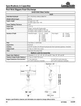
Skid Steer/Tractor Requirements
The auger is designed to attach to skid steers, track
loaders, or tractor front-end loaders equipped with a skid
steer type quick attach hitch that meets SAE. It also can
be attached to the back of tractors with a Cat. I or Cat. II
3-point hitch, or to the side of a tractor front-end loader
bucket. The following requirements must be met:
Hydraulic Pressure Rating . . . . . . . 1,500 - 3,500 PSI
Hydraulic Flow Rate
Model HD25 . . . . . . . . . . . . . . . . . . . . . . 5-12 gpm
Model HD35 . . . . . . . . . . . . . . . . . . . . . . 10-25 gpm
Max Torque @ 2,500 PSI
Model HD25 . . . . . . . . . . . . . . . . . . . . . . 700 ft-lbs.
Model HD35 . . . . . . . . . . . . . . . . . . . . . 1,605 ft-lbs.
Hydraulic Connections . . . . . . . . . . . 1 - Duplex Outlet
Power Machine Shutdown Procedure
The following are basic power machine shutdown
procedures. Follow these procedures and any additional
shutdown procedures provided in your power machine
Operator’s Manual before leaving the operator’s seat.
1. Reduce engine speed and shut-off all power to the
Post Hole Digger.
2. Park on solid, level ground and lower Post Hole
Digger until it is flat on the ground or on non-concrete
support blocks. If lowering loader arms, make sure
loader arms are fully down.
3. If shutting down a tractor, put tractor in park or set
park brake.
4. Turn off engine, and remove switch key to prevent
unauthorized starting.
5. Relieve all hydraulic pressures.
6. If included, raise seat bar and move controls until
both lock.
7. Wait for all components to come to a complete stop
before leaving the operator’s seat.
8. Use steps, grab-handles, and anti-slip surfaces
when stepping on and off the power machine.
Section 1: Assembly & Set-up

Section 1: Assembly & Set-up
Table of Contents
10/16/19HD25 and HD35 Hydraulic Post Hole Diggers 317-076M
14
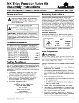
HD 3-Point Mount Assembly
Figure 1-1
35992
70145
8. Raise tractor lower 3-point arms until end of boom is
approximately 18" above ground.
9. Position gearbox and motor assembly (#7) under
boom assembly (#2).
10. Remove one cotter pin (#11) and hanger pin (#13)
from gearbox (#7).
11. Align gearbox mounting holes with boom mounting
hole and reinsert hanger pin (#13). Secure hanger
pin with cotter pin (#11). Bend one or more legs of
cotter pin to keep it from falling out.
12. Attach lower spring clamp half (#6) and upper plain
clamp half (#5) to boom (#2) 12" up from hanger
pin (#13) with 3/8"-16 x 1 1/4" GR5 bolts (#8) and
locknuts (#9). Tighten locknuts to the correct torque.
13. Attach extension spring (#14) to spring clamp (#6)
and tab (#4) on hydraulic motor (#15).
14. Screw 90
o
elbows (#16) into ports in motor (#15).
Point elbows straight back and tighten.
15. Thread adapter fittings (#17) to other end of hydraulic
hoses (#19) and tighten.
16. Quick release couplers (#18) are furnished by
customer. Thread quick release couplers (#18) to
adapter fittings (#17).
17. Screw 66" long hydraulic hoses (#19) into motor
fittings (#16) and tighten.
18. Fill gearbox with gear lube. Refer to “Gear Lube
Fluid Level” on page 42 for detailed instructions.
19. Relocate slow moving sign (#21) from back of the
tractor to mounting bracket (#20)
IMPORTANT: The gearbox is shipped without gear
lube and must be filled before operating the digger.
HD 3-Point Mount Assembly
Refer to Figure 1-1:
1. Remove tractor top center 3-point link (not shown).
Keep hitch pin and retaining pin for future use.
2. Attach boom (#2) to the tractor’s top center link hole
using existing hitch pin and retaining pin.
3. Attach yoke (#1) to the tractor’s 3-point lift arms with
two 5/16" x 1 3/4" linchpins supplied by customer.
4. Connect lower 3-point sway bars or adjust sway links
to retain digger side to side movement.
5. Rotate boom (#2) and yoke (#1) up until pin (#12) can
be inserted into the boom’s middle hole.
6. Place spacers (#3) between digger yoke (#1) and
boom (#2) as shown and insert pivot pin (#12).
Secure pin with cotter pin (#10). Bend one or more
legs of cotter pin to retain pin.
7. Boom and yoke pivot connection may need
readjusting to get the desired hole depth and auger
transport clearance. Refer to “Post Hole Digging
Depth” on page 25.
IMPORTANT: Cab tractors: Glass can break if
contacted by the post hole digger boom when lifting
or transporting the unit, depending on the tractor
and its three point hook-up geometry.
NOTE: It may be necessary to move center 3-point
hitch pin to the top mounting hole on the tractor
and/or adjust yoke and yoke pin to a mounting hole
farther away from the tractor. Refer to “Check Post
Hole Digger Clearance” on page 24.
NOTE: The Post Hole Digger will be easier to
assemble if assembled to a tractor.

Section 1: Assembly & Set-up
Table of Contents
10/16/19
HD25 and HD35 Hydraulic Post Hole Diggers 317-076M
15
20. If needed, a slow moving sign can be purchased from
your nearest Land Pride dealer. Refer to “Slow
Moving Vehicle Sign Accessory” on page 39.
21. Skip to “Auger Assembly” on page 18.
HD Bucket Mount Assembly
Refer to Figure 1-2:
1. The Bucket Mount Post Hole Digger can be mounted
on the left-hand or right-hand side of bucket.
2. Locate mounting bracket (#1) on the bucket sidewall
where it is most convenient for the operator to view
the auger.
3. Using back plate (#3) as a guide, locate and drill (4)
9/16" dia. holes in the bucket side wall.
4. Mount mounting bracket (#1) to the bucket sidewall
with 1/2"-13 x 1 3/4" GR5 bolts (#2), back plate (#3),
and 1/2" flange nuts (#4) as shown. Tighten nuts to
the proper torque.
5. Attach clevis (#5) to mounting bracket (#1) with
1" x 4 11/16" clevis pin (#6) and cotter pins (#7). Bend
one or more legs of the cotter pin to retain pin.
6. Remove one cotter pin (#9) and hanger pin (#8) from
gearbox (#16).
7. Align mounting holes in gearbox (#16) with mounting
holes in clevis (#5) and reinsert hanger pin (#8).
Secure hanger pin with cotter pin (#9). Bend one or
more legs of cotter pin to keep it from falling out.
IMPORTANT: If digger is mounted on the left-hand
side, then hydraulic motor should be rotated 180
degrees so that hydraulic fittings are facing out.
HD Bucket Mount Assembly (Right-Hand Side Shown)
Figure 1-2
Important: Make sure gearbox is mounted
with hydraulic motor (#14) extending
towards the rear and motor ports facing
out as shown.
73188
8. Attach extension spring (#10) to clevis (#5) &
tab (#17) on hydraulic motor (#14).
9. Attach 90
o
elbows (#15) to ports in hydraulic
motor (#14). Rotate elbows to point straight back as
shown and tighten.
10. Screw MJIC end of adapter fittings (#13) to one end
of 292" long hydraulic hoses (#11 & #12) and tighten.
11. Screw quick release couplers (#19) (couplers
furnished by customer) to fittings (#13) until tight.
12. Screw other end of hydraulic hoses (#11 & #12) to
elbows (#15) until tight.
13. Attach "Underground Digging Hazard", decal 488-
194C to the side of the bucket as shown. Refer to
“Safety Labels” on page 6 for detailed instructions.
14. Zip ties (not shown) to be used later during tractor
hook-up.
15. Fill gearbox with gear lube. Refer to “Gear Lube
Fluid Level” on page 42.
16. Skip to “Auger Assembly” on page 18
NOTE: Hydraulic hoses (#11 & #12) and adapter
fittings (#13) are optional and may not be included.
IMPORTANT: The gearbox is shipped without gear
lube and must be filled before operating the digger.

Section 1: Assembly & Set-up
Table of Contents
10/16/19HD25 and HD35 Hydraulic Post Hole Diggers 317-076M
16
Skid/Loader Mount Assembly
Refer to Figure 1-3:
Determine which mount will be used with the skid/loader
hitch mount (Center Mount “A” or Offset Mount “B”).
Follow instructions below based on type of mount to be
used.
Center Mount & Offset Mount
Refer to Figure 1-3:
1. Attach gearbox rest (#4) to lower center mount
bracket “A” or to lower offset mount bracket “B” with
3/8"-16 x 1 1/4" GR5 carriage bolts (#5) and flange
locknuts (#6). Tighten locknuts to the correct torque.
2. Attach clevis (#2) to upper center mount bracket “A” or
to upper offset mount bracket “B” with clevis
pin (#8) and cotter pin (#7). Bend one or more legs of
cotter pin to keep it from falling out.
3. Remove one cotter pin (#7) and hanger pin (#9) from
gearbox (#10).
4. Attach gearbox & motor assembly (#10) to clevis (#2)
with pin (#9) and cotter pin (#7). Bend one or more
legs of cotter pin to keep pin from falling out.
5. Attach spring (#3) to tab (#1) and clevis (#2).
6. Fill gearbox with gear lube. Refer to “Gear Lube
Fluid Level” on page 42 for detailed instructions.
7. Skip to “Skid/Loader Hose Assembly” on page 17.
IMPORTANT: Make sure gearbox is mounted with
hydraulic motor on the left-hand side and motor
ports facing the skid/loader mounting plate.
IMPORTANT: The gearbox is shipped without gear
lube and must be filled before operating the digger.
Center Mount & Offset Mount (Center Mount Shown)
Figure 1-3
OFFSET MOUNT
CENTER MOUNT
Make sure gearbox is
mounted as shown with
hydraulic motor on this
side and motor ports
facing the skid/loader
hitch mount.
35977
/