Page is loading ...

LG
Multi Type Air Conditioner
INSTALLATION MANUAL
LG
website http://www.lgservice.com
e-mail http://www.lgeservice.com/techsup.html
IMPORTANT
• Please read this installation manual completely before
installing the product.
• When the power cord is damaged, replacement work shall
be performed by authorized personnel only.
• Installation work must be performed in accordance with
the national wiring standards by authorized personnel
only.

2 Multi type Air Conditioner
Multi Type Ceiling Duct Air Conditioner Installation Manual
TABLE OF CONTENTS
Installation Parts Provided .........................................3
Safety Precautions......................................................4
Installation of indoor, outdoor unit............................7
Connecting Pipes to the Indoor Unit.......................19
Connecting Pipes to the Outdoor Unit....................24
Checking the Drainage and Forming
the Piping...................................................................24
Connection of the Cable...........................................25
Air Purging of the Connecting Pipes and
the Indoor Unit...........................................................27
Group Control ............................................................28
Two Thermistor System ............................................28
E.S.P (External Static Pressure) Setting.................29
How to set E.S.P?......................................................30
Test Running..............................................................32
❏ Level gauge
❏ Screw driver
❏ Electric drill
❏ Hole core drill (ø50mm)
❏ Horizontal meter
❏ Flaring tool set
❏ Specified torque wrenches
1.8kg.m, 4.2kg.m, 5.5kg.m, 6.6kg.m
(different depending on model No.)
❏ Spanner .................Half union
❏ A glass of water
❏ Screw driver
❏ Hexagonal wrench(4mm)
❏ Gas-leak detector
❏ Vacuum pump
❏ Gauge manifold
❏ Owner's manual
❏ Thermometer
❏ Holder Remote Control
Installation Requirements
Required Tools

Installation Parts Provided
Installation Manual 3
Installation Parts Provided
Standard Type
Air filters
Air outlet vents
Air intake vents
Remote Controller
Remote Controller
Air outlet vents
Air intake vents
(Side)
(Rear)
Air intake
vents
Air outlet vents
Piping
Drain hose
Control cover
Connecting wire
Indoor Unit
Outdoor Unit

4 Multi type Air Conditioner
Safety Precautions
To prevent injury to the user or other people and property damage, the following instructions
must be followed.
■ Incorrect operation due to ignoring instruction will cause harm or damage. The seriousness
is classified by the following indications.
■ Meanings of symbols used in this manual are as shown below.
WARNING
CAUTION
This symbol indicates the possibility of death or serious injury.
This symbol indicates the possibility of injury or damage.
WARNING
Be sure not to do.
Be sure to follow the instruction.
Safety Precautions
Do not use a defective or underrated circuit
breaker. Use this appliance on a dedicated
circuit.
• There is risk of fire or electric shock.
For electrical work, contact the dealer,
seller, a qualified electrician or an
Authorized Service Center.
• Do not disassemble or repair the product.
There is risk of fire or electric shock.
Always ground the product.
• There is risk of fire or electric shock.
Install the panel and the cover of control box
securely.
• There is risk of fire or electric shock.

Installation Manual 5
Safety Precautions
Always intstall a dedicated circuit and
breaker.
• Improper wiring or installation may cause fire
or electric shock.
Use the rated breaker or fuse correctly.
• There is risk of fire or electric shock.
Do not modify or extend the power cable.
• There is risk of fire or electric shock.
Be cautious when unpacking and installing
the product.
•
Sharp edges could cause injury. Be especially
careful of the case edges and the fins on the
condenser and evaporator.
For installation, always contact the dealer or
an Authorized Service Center.
• There is risk of fire, electric shock, explosion or
injury.
Do not install the product on a defective
installation stand.
• It may cause injury, accident or damage to the
product.
Be sure the installation area
does not deteriorate with
age.
•
If the base collapses, the air
conditioner could fall with it,
causing property damage, product
failure and personal injury.
Do not let the air conditioner
run for a long time when the
humidity is very high and a
door or a window is left open.
• Moisture may condense and
wet or damage furniture.
Do not store or use
flammable gas or
combustibles near the
prodcut.
• There is risk of fire or failure
of product.
Gasolin

6 Multi type Air Conditioner
Safety Precautions
CAUTION
Always check for gas (refrigerant) leakage
after installation or repair of product.
• Low refrigerant levels may cause failure of
product.
Install the drain hose to ensure that water is
drained away properly.
• A bad connection may cause water leakage.
Keep level even when installing the product.
• To avoid vibration or water leakage.
Do not install the product where the noise
or hot air from the outdoor unit could
damage the neighborhoods.
• It may cause a problem for your neighbors.
90°

Installation Manual 7
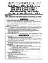
Installation of Indoor, Outdoor Unit
Installation of Indoor, Outdoor Unit
Selection of the best location
1) Indoor unit
Select location
Install the air conditioner in the location that satisfies the
following conditions.
• The place shall easily bear a load exceeding four times the
indoor unit’s weight.
• The place shall be able to inspect the unit as the figure.
• The place where the unit shall beleveled.
• The place shall allow easy water drainage.(Suitable dimension
“H” is necessary to get a slope to drain as figure.)
• The place shall easily connect with the outdoor unit.
• The place where the unit is not affected by an electrical noise.
• The place where air circulation in the room will be good .
• There should not be any heat source or steam near the unit
• Do not have any heat or steam near the unit.
• Select a place where there are no obstacles in front of the unit.
• Make sure that condensation drainage can be conveniently
routed away.
• Do not install near a doorway.
• Ensure the spaces indicated by arrows from the wall, ceiling,
fence or other obstacles.
• Use a stud finder to locate studs to prevent unnecessary
damage to the wall.
2) Outdoor unit
• If an awning is built over the unit to prevent direct sunlight or
rain exposure, be careful that heat radiation from the
condenser is not restricted.
• There should not be any animals or plants which could be
affected by hot air discharged.
• Ensure the spaces indicated by arrows from the wall, ceiling,
fence or other obstacles.
H
600600
Top view
(unit: mm)
Front view
Front
Inspection hole
(600X600)
Control box
1000
More than 5cm
More than
5cm
More than 2.3m
More than
5cm
More than
90cm
More than 90cm
More than 120cm
More than 90cm
More than
90cm
Fence or
obstacles
Fence or
obstacles
Fence or
obstacles

8 Multi type Air Conditioner
Installation of Indoor, Outdoor Unit
Distributor Type (m)
Piping length and elevation
50 A = 25 25 15 20 7.5
30 B = 30 - - 20 7.5
Total Length
Max Main Pipe
Length (A/B)
Total Branch
Pipe Length
Max Branch
Pipe Length
Max Elevation
(h1/h2)
In - In
Elevation (h3)
h1
h2
A
B
Branch Pipe
Main Pipe
Distributor
h3
Distributor Type
CAUTION: Capacity is based on standard length and maximum allowance
length is on the basis of reliability. Oil trap should be installed every 5~7
meters.
When installing 36k Btu/h indoor unit,
use the short tube connector.
(not branch distributor type)
NOTICE
Capacity (Btu/h)
With
Distributor
60K
None
Distributor
Short tube connector
(for A-UNIT)

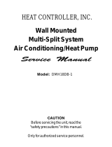
Installation of Indoor, Outdoor Unit
Installation Manual 9
Piping installation
Ø12.7/6.35
Distributor
(3 room)
Distributor
(2 room)
12,000 Btu/h Indoor Unit
12,000 Btu/h Indoor Unit
12,000 Btu/h Indoor Unit
24,000 Btu/h Indoor Unit
Ø12.7/6.35
Ø12.7/6.35
Ø15.88/6.35
Ø15.88/6.35
Circuit 1
(TPS Cycle)
Circuit 2
(Single cycle)
Ø12.7/6.35
Ø15.88/6.35
(at 24,000 Btu/h
Indoor Unit)
18,000 Btu/h Indoor Unit
or 24,000 Btu/h Indoor Unit
18,000 Btu/h Indoor Unit
or 12,000 Btu/h Indoor Unit
24,000 Btu/h Indoor Unit
Ø12.7/6.35
Ø15.88/6.35
Ø15.88/6.35
Circuit 1
(TPS Cycle)
Circuit 1
(TPS Cycle)
Circuit 2
(Single cycle)
36,000 Btu/h Indoor Unit
24,000 Btu/h Indoor Unit
Ø15.88/6.35
Ø15.88/6.35
Short tube
Circuit 2
(Single cycle)
Case 1
Case 2
Case 3

10 Multi type Air Conditioner
Installation of Indoor, Outdoor Unit
Indoor unit installation
■ Installation of Unit
Install the unit above the ceiling correctly.
• Apply a joint-canvas between the unit and
duct to absorb unnecessary vibration.
• Apply a filter Accessory at air return hole.
• Install the unit leaning to a drainage hole
side as a figure for easy water drainage.
• A place where the unit will be leveled and
that can support the weight of the unit.
• A place where the unit can withstand its
vibration.
• A place where service can be easily
performed.
CASE 1
POSITION OF SUSPENSION BOLT
CASE 2
POSITION OF CONSOLE BOLT
(Unit:mm)
Drainage hole
M10 Nut
M10 SP. washer
M10 washer
X 4
X 4
(Local
supply)
X 4
M10 Nut
M10 SP. washer
M10 washer
X 4
X 4
(Local
supply)
X 4
A
B
C
1-3 mm
D
(G)
H
I
EF
18K BTU/h
948 880 355 45.5 450 30 87 750 163
24K BTU/h
30K BTU/h
1232 1180 315 45.5 450 30 87 830 186
36K BTU/h
Dimension
Capacity
ABCDEF(G)HI

Installation Manual 11
Installation of Indoor, Outdoor Unit
• Select and mark the position for fixing bolts.
• Drill the hole for set anchor on the face of
ceiling.
• Insert the set anchor and washer onto the
suspension bolts for locking the suspension
bolts on the ceiling.
• Mount the suspension bolts to the set
anchor firmly.
• Secure the installation plates onto the
suspension bolts (adjust level roughly)
using nuts, washers and spring washers.
1 Set anchor
Old building New building
2 Plate washer
3 Spring washer
4 Nut
5 Suspension
bolts
• Local supply
Set anchor
Plate washer - M10
Spring washer - M10
Nut - W3/8 or M10
Suspension bolt - W3/8 or M10
CAUTION: Tighten the nut and
bolt to prevent unit falling

12 Multi type Air Conditioner
Installation of Indoor, Outdoor Unit
Ceiling
CAUTION
1~3mm
Drainage hole
Drainage hole
U-Trap
B
C
A ≥ 70mm
B ≥ 2C
C ≥ 2 x SP
SP = External Pressure
(mmAq)
Ex) External Pressure
= 10mmAq
A ≥ 70mm
B ≥ 40mm
C ≥ 20mm
A
Make sure to be closed.
Unit
Drainage pipe
(Local supply)
Thermal insulator
(Local supply)
Drainage hole
CAUTION FOR GRADIENT OF
UNIT AND DRAIN PIPING
Lay the drain hose with a downward
inclination so water will drain out.
Front of view
• Always lay the drain with downward
inclination (1/50 to 1/100).
Prevent any upward flow or reverse flow
in any part.
• 5mm or thicker formed thermal insulator
shall always be provided for the drain
pipe.
• Install the P-Trap (or U-Trap) to prevent
a water leakage caused by the blocking
of intake air filter.
Applied U-Trap Dimension
1. Install declination of the indoor unit is very important for the drain of the duct type air
conditioner.
2. Minimum thickness of the insulation for the connecting pipe shall be 5mm.
• The unit must be horizontal or declined to the drain hose connected when finished
installation.
CORRECT
CORRECT
INCORRECT
INCORRECT
• Upward routing not
allowed

Installation Manual 13
Installation of Indoor, Outdoor Unit
• Drill the piping hole with 70mm dia, hole
core drill.
• Piping hole should be slightly slant to the
outdoor side.
INSULATION, OTHERS
Insulate the joint and tubes completely.
All thermal insulation must comply with local requirement.
INDOOR UNIT
REFRIGERANT PIPE
• Insulate and tape the gas piping.
■ After all workings are finished, check the working and operation.
• Air distribution Is the air circulation good?
• Drain Is the drainage smooth and no sweating?
• Gas leakage Is the piping connection correct?
• Wiring Is the wiring connection correct?
• Lock-bolt Is the lock-bolt of compressor loosened?
THERMAL INSULATION
TEST AND CHECK
5~7mm
Indoor Outdoor
WALL
Make sure that there is no clearance here.
Overlap with thermal
insulator for piping.
Thermal insulator for refrigerant pipe
(Local supply)
Thermal insulator for
piping(Local supply)
Hose clip for thermal insulator(Local supply)
Union for liquid pipe
Refrigerant pipe and thermal
insulator(Local supply)
Union for gas pipe
Thermal insulator for refrigerant pipe
(Local supply)
Hose clip for thermal insulator
(Local supply)
Power cable
Thermal insulator
Gas pipe
Liquid pipe
Tape

14 Multi type Air Conditioner
Installation of Indoor, Outdoor Unit
INSTALLATION OF REMOTE CONTROL BOX
Install the remote control box
and cord correctly.
• Although the room temperature sensor is in the indoor unit, the remote control box
should be installed in such places away from direct sunlight and high humidity.
INSTALLATION OF THE REMOTE CONTROL BOX
• Select places that is not splashed by
water.
• Select control position after receiving
customer approval.
• The room temperature sensor of the
thermostat for temperature control is
built in the indoor unit.
• This remote controller equipped with
liquid crystal display. If this position is
higher or lower, display is difficult to see.
(The standard height is 1.2~1.5m high)
ROUTING OF THE REMOTE CONTROL CORD
• Keep the remote control cord away from
the refrigerant piping and the drain
piping.
• To protect the remote control cord from
electrical noise, place the cord at least
5cm away from other power cables.
(Audio equipment, Television set, etc)
• If the remote control cord is secured to a
wall, provide a trap at the top of the cord
to prevent water droplets from running.
POINT OF REMOTE CONTROLLER INSTALLATION
DISASSEMBLING OF THE REMOTE CONTROLLER
ELECTRICAL WIRING TO THE INDOOR UNIT
Make sure that wire and terminal
numbers are matched on unit side
and remote controller side.
(Main board)
CN REMO
The maximum length of the cord is 100m.
If the length of the cord exceeds 50m, use a wire size greater than 0.5mm
2
.
Remote controller
CN REMO
Remote
control
box body
Lever carefully
the box open
using a screw
driver, etc.
Front case
The lower part
Face of wall
Upper notch
Upper flange
Under plate
Remote
control cord
Remote
control unit
Tapping screw
(Local supply)
Lower notch
Face of wall
Upper notch
Lower notch
Switch box
(Local supply)
Under plate
Remote
control unit
Remote
control cord
Screw
(Local supply)
Cord
clamp
Push hand
(Part B)
(Part A)
FIXING OF REMOTE
CONTROL CORD
1. Fix the cord clamps on the wall
by ø3 tapping screws(Local supply).
2. Fix the remote control cord.
PROCEDURE OF INSTALLATION
1. Fix the under plate on the switch box by
screws(Local supply). In this case, fit the under
plate on the wall, and be careful of deformation.
2. Receive the remote control cord in the switch
box.
3. Hook the remote control unit on the under plate.
WHEN THE REMOTE CONTROL BOX IS
INSTALLED WITH THE CORD BURIED.
PROCEDURE OF INSTALLATION
1. Fix the under plate on the wall by self tapping
screws (accessory).
2. Make a slit (Part A) at the top side of the remote
control box by nipper.
3.Rout the cord as shown in the following figure. In
this case, push the cord into the around of
case(Part B).
4. Hook the remote control unit on the under plate.
WHEN THE REMOTE CONTROL BOX IS
INSTALLED WITH THE CORD EXPOSED.

Installation Manual 15
Installation of Indoor, Outdoor Unit
WIRED REMOTE CONTROLLER INSTALLATION
• Since the room temperature sensor is in the remote controller, the remote controller box should
be installed in a place away from direct sunlight, high humidity and direct supply of cold air to
maintain proper space temperature.
Install the remote controller about 5ft(1.5m) above the floor in an area with good air circulation at
an average temperature.
Do not install the remote controller where it can be affected by:
- Drafts, or dead spots behind doors and in corners.
- Hot or cold air from ducts.
- Radiant heat from sun or appliances.
- Concealed pipes and chimneys.
- Uncontrolled areas such as an outside wall behind the remote controller.
- This remote controller is equipped with a seven segment LED. display. For proper display of the
remote controller LED's, the remote controller should be installed properly as shown in Fig.1.
(The standard height is 1.2~1.5 m from floor level.)
Operation unit
ZONE
1234
Humidify
JET
AUTO
AUTO SWING OPERATION
FAN SPEED
Program set
SUB FUNCTION
SET TEMP
Room Temp
HI
MED
LO
Heater
Defrost
Filter
Preheat
Out door
Time
Timer
On
Set no. Time
Off
01 03 05 07 09 11 13 15 17 19 21 23
O
p
e
ra
ti
o
n
u
n
i
t
Z
O
N
E
1
2
34
H
u
m
i
d
i
f
y
J
E
T
A
U
T
O
A
U
T
O
S
W
I
N
G
O
P
E
R
A
T
I
O
N
F
A
N
S
P
E
E
D
P
ro
g
ra
m
s
e
t
S
U
B
F
U
N
C
T
I
O
N
S
E
T
T
E
M
P
R
o
o
m
T
e
m
p
H
I
M
E
D
L
O
H
e
a
t
e
r
D
e
f
r
o
s
t
F
i
l
t
e
r
P
r
e
h
e
a
t
O
u
t
d
o
o
r
T
im
e
T
im
e
r
O
n
S
e
t
n
o
.
T
i
m
e
O
f
f
0
1
0
3
0
5
0
70
9
1
1
1
3
1
5
1
71
92
1
2
3
5feet
(1.5meters)
no
no
no
yes
Operation unit
ZONE
1234
Humidify
JET
AUTO
AUTO SWING OPERATION
FAN SPEED
Program set
SUB FUNCTION
SET TEMP
Room Temp
HI
MED
LO
Heater
Defrost
Filter
Preheat
Out door
Time
Timer
On
Set no. Time
Off
01 03 05 07 09 11 13 15 17 19 21 23
Fig.1 Typical locations for remote controller

16 Multi type Air Conditioner
Installation of Indoor, Outdoor Unit
Flared connection (Union)
Flared connection
(Service valve, Ball valve)
Use a seemliness tube
Factory charged
Indoor
Outdoor
■ Select the following location
• A place where the air conditioner can get good ventilation.
• A place where it shall not annoy the neighbors.
• A place where the unit shall be leveled and that can support the weight of unit and
withstand its vibrations.
■ Keep a maintenance space
* One side must be 90Cm for service.
REFRIGERANT PIPING
INSTALLATION OF OUTDOOR UNIT
Perform the work according to the Service
Manual or Installation Guide.
Select a location that satisfies the following
conditions. Install the unit firmly in place.
• Use two spanners when connecting the
refrigerant pipe to the unit.
• Make a bend with a radius as large as
possible.
• Perform air purge with R-22 or vacuum drying.
• When piping work is finished, check all joints.
■
Add refrigerant if piping over 7.5m(at 30g/m, non
distributor type)
.
■
Add refrigerant if piping over 3m(main pipe),
4.5m(branch pipe) as shown below, distributor
type.
15.88 6.35 30g/m
12k Btu/h 12.7 6.35 20g/m
18k Btu/h 12.7 6.35 20g/m
24k Btu/h 15.88 6.35 30g/m
Above 90Cm
*Above 90Cm
Above
90Cm
Above
90Cm
Main Pipe
Branch Pipe
Additional
Pipe
Liquid Gas

Installation Manual 17
Installation of Indoor, Outdoor Unit
Control terminal board
Control box
Control box cover
(On which the Electric
Wiring Connection is put)
AA
view
Remote
control cord
Connection
cord between
the indoor unit
and the
outdoor unit
Cord clamper
1
1
Outdoor
Indoor
Main
power source
Switch box
Circuit Breaker
Cover control
Terminal
board
Terminal
board
ELECTRICAL WIRING
INDOOR UNIT
• Remove the control box cover for
electrical connection between the
indoor and outdoor unit.
(Remove screws ➀.)
• Use the cord clamper to fix the cord.
Perform the electrical wiring work according to the
electrical wiring connection.
WIRING CONNECTION
OUTDOOR UNIT
• Remove the control cover for wiring
connection.
• Use the cord clamper to fix the cord.
• Earthing work
Connect the cable of diameter 1.6mm
2
or more to the earthing terminal
provided in the control box and do
earthing.
Please check !!
• All wiring must comply with local requirements.
• Select a power source that is capable of
supplying the current required by the air
conditioner.
• Use a recognized circuit breaker between the
power source and the unit. A disconnection
device to adequately disconnect all supply
lines must be fitted.
• Capacity of circuit breaker(at 3 Phase, 25A).

18 Multi type Air Conditioner
Installation of Indoor, Outdoor Unit
The wall you select should be strong and solid
enough to prevent vibration
1. Mount the installation plate on the wall with
type "A" screws. If mounting the unit on a
concrete wall, use anchor bolts.
• Mount the installation plate horizontally by
aligning the centerline using a level.
2. Measure the wall and mark the centerline. It
is also important to use caution concerning
the location of the installation plate-routing
of the wiring to power outlets is through the
walls typically. Drilling the hole through the
wall for piping connections must be done
safely.
How to fix installation plate
Installation Plate
Type "A" screw
Installation plate
Ø70mm
Left rear piping Right rear piping
C
D
B
A
Ø70mm
(SR, ST)
SR(12k) 0 40 20 40
ST(18k~24k) 105 0 210 0
CHASSIS (Grade)
Distance (mm)
ABCD

Installation Manual 19
Connecting Pipes to the Indoor Unit
Connecting Pipes to the Indoor Unit
Preparation of Piping
Main cause of gas leakage is defect in
flaring work. Carry out correct flaring work
in the following procedure.
1) Cut the pipes and the cable.
■ Use the accessory piping kit or the pipes
purchased locally.
■ Measure the distance between the indoor
and the outdoor unit.
■ Cut the pipes a little longer than measured
distance.
■ Cut the cable 1.5m longer than the pipe
length.
2) Burrs removal
■ Completely remove all burrs from the cut
cross section of pipe/tube.
■ Put the end of the copper tube/pipe to
downward direction as you remove burrs
in order to avoid to let burrs drop in the
tubing.
3) Putting nut on
■ Remove flare nuts attached to indoor and
outdoor units, than put them on pipe/tube
having completed burr removal.
(Not possible to put them on after flaring
work)
4) Flaring work
■ Carry out flaring work using flaring tool as
shown below.
Firmly hold copper tube in a bar(or die) as
indicated dimension in the table above.
5) Check
■ Compare the flared work with figure.
■ If flare is noted to be defective, cut off the
flared section and do flaring work again.
Copper
tube
90°
Slanted Uneven Rough
Pipe
Reamer
Point down
Flare nut
Copper tube
Bar
Copper pipe
Clamp handle
Red arrow mark
Cone
Yoke
Handle
Bar
"A"
Inclined
Inside is shining without scratches.
Smooth all round
Even length
all round
Surface
damaged
Cracked Uneven
thickness
= Improper flaring =
Outside Diameter "A"
1/4" 0~0.5
3/8" 0.5~0.8
1/2" 0.5~0.8
5/8" 0.8~1.0
3/4" 1.0~1.3

20 Multi type Air Conditioner
Connecting Pipes to the Indoor Unit
6) Pipe bending
Annealed copper pipe with small diameter (ø6.35 or ø9.52) can be easily bent manually. In this
case, secure large R(radius) for the bend section and gradually bend pipe. If annealed copper
pipe is large in diameter (ø15.88 or ø19.05), bend pipe with bender. Use bender appropriate for
the pipe diameter.
7)
Brazing
In refrigerant piping, bending (in particular, acute bending) must be minimized to reduce piping
resistance. Bending is, however, necessary in some places by virtue of the installation position
of devices auxiliary to the packaged air conditioner, or of the building structure, piping distance
or finishing appearance. If a more acute bend is required than that attainable by pipe bender,
perform brazing using ready-made elbow. Aside from this function, brazing also serves to
connect straight pipes, generally using ready-made sockets. While brazing, protect piping
against heat with wet cloth to avoid damaging valve packing or burning thermal insulator with
burner heat. While brazing, blow inert gas (nitrogen gas or carbonic gas) to prevent formation of
oxidation film in copper piping; otherwise, the refrigerant circuit will clog. The blowing of nitrogen
gas (or carbonic gas) through 3-way valves is described in the following:
8) Refrigerant piping(Flare piping)
When connecting piping, be sure to keep piping dry(keep piping away from water), clean (keep
piping away from dust) and airtight (avoid refrigerant leakage).
When connecting piping on rainy days or making a through-hole in wall, take due care to
prevent water or plaster from entering piping.
Water enters Plaster enters
CAUTION:
a. This procedure is designed to
prevent formation of oxidation film
by filling piping with inert gas. Note
that excessive gas pressure will
generate pinholes at brazed points.
(Nitrogen gas: Supply pressure
0.05~0.1kg/cm
2
G)
b. When supplying inert gas, be sure
to open one end of piping.
/