Page is loading ...

P/NO : 3828A20567R
www.lg.com
INSTALLATION MANUAL
AIR CONDITIONER
• Please read this installation manual completely before installing the product.
• Installation work must be performed in accordance with the national wiring
standards by authorized personnel only.
• Please retain this installation manual for future reference after reading it
thoroughly.
TYPE : MULTI
ENGLISH
ESPAÑOL
PORTUGUÊS

2 Air Conditioner
Air Conditioner Installation Manual
TABLE OF CONTENTS
Installation Requirements
Required Tools
Installation Parts Provided.........................................3
Safety Precautions......................................................4
Installation of indoor, outdoor unit .....................7~28
Flaring Work and Connection of Piping ...........29~31
Connecting the Cable between Indoor Unit and
Outdoor Unit........................................................32~33
Checking the Drainage, Forming the Pipings and
Long Pipe Setting................................................34~35
Air Purging and Evacuation...............................36~37
Test Running..............................................................38
Optional Operation - Duct Types.......................39~42
Combination indoor units ........................................43
Installation guide at the seaside..............................44
o Level gauge
o Screw driver
o Electric drill
o Hole core drill (ø50mm)
o Horizontal meter
o Flaring tool set
o Specified torque wrenches
1.8kg.m, 4.2kg.m, 5.5kg.m, 6.6kg.m
(different depending on model No.)
o Spanner .................Half union
o A glass of water
o Screw driver
o Hexagonal wrench(4mm)
o Gas-leak detector
o Vacuum pump
o Gauge manifold
o Owner's manual
o Thermometer
o Holder Remote Control

Installation Parts Provided
Installation Manual 3
ENGLISH
Installation Parts Provided
Outdoor Unit
Wall Mounted Type
Installation plate
Type "B" screws (2EA)
Type "A" screw (8 EA)
Holder Remote Control
more than
700
more than
300
more than
300
Air Outlet
Air Intake
(side, rear)
Connection pipe
Drain hose
Connecting wire
Control cover
more than
300
(unit : mm)

4 Air Conditioner
Safety Precautions
To prevent injury to the user or other people and property damage, the following instructions
must be followed.
n Incorrect operation due to ignoring instruction will cause harm or damage. The seriousness
is classified by the following indications.
n Meanings of symbols used in this manual are as shown below.
WARNING
CAUTION
This symbol indicates the possibility of death or serious injury.
This symbol indicates the possibility of injury or damage.
Be sure not to do.
Be sure to follow the instruction.
Safety Precautions
WARNING
n Installation
Install the panel and the cover of
control box securely.
• There is risk of fire or
electric shock.
Always install a dedicated
circuit and breaker.
• Improper wiring or
installation may cause fire or
electric shock
Use the correctly rated breaker
or fuse.
• There is risk of fire or
electric shock.
Do not use a defective or
underrated circuit breaker. Use
this appliance on a dedicated
circuit.
• There is risk of fire or
electric shock.
For electrical work, contact the
dealer, seller, a qualified
electrician, or an Authorized
Service Center.
•
Do not disassemble or repair
the product. There is risk of
fire or electric shock.
Always ground the product.
• There is risk of fire or
electric shock.

ENGLISH
Installation Manual 5
Safety Precautions
Do not modify or extend the power cable.
• There is risk of fire or electric shock.
Be cautious when unpacking and installing the
product.
•
Sharp edges could cause injury. Be especially
careful of the case edges and the fins on the
condenser and evaporator.
For installation, always contact the dealer or an
Authorized Service Center.
• There is risk of fire, electric shock, explosion,
or injury.
Do not install the product on a defective
installation stand.
• It may cause injury, accident,
or damage to the product.
Be sure the installation area does not
deteriorate with age.
•
If the base collapses, the air conditioner could fall with
it, causing property damage, product failure, and
personal injury.
Do not let the air conditioner run for a long time when
the humidity is very high and a door or a window is
left open.
• Moisture may condense and wet or damage
furniture.
Do not store or use flammable gas or combustibles near the product.
• There is risk of fire or failure of product.
Use a vacuum pump or Inert (nitrogen) gas when
doing leakage test or air purge. Do not compress air
or Oxygen and Do not use Flammable gases.
Otherwise, it may cause fire or explosion.
• There is the risk of death, injury, fire or
explosion.
n Operation

6 Air Conditioner
Safety Precautions
Always check for gas (refrigerant) leakage after
installation or repair of product.
• Low refrigerant levels may cause failure of
product.
Install the drain hose to ensure that water is
drained away properly.
• A bad connection may cause water leakage.
Keep level even when installing the product.
• To avoid vibration or water leakage.
Do not install the product where the noise or hot air
from the outdoor unit could damage the
neighborhoods.
• It may cause a problem for your neighbors.
Don't let people to lift and transport the
product. (Use fork lift)
• Avoid personal injury.
Do not install the product where it will be
exposed to sea wind (salt spray) directly.
• It may cause corrosion on the product.
Corrosion, particularly on the condenser and
evaporator fins, could cause product
malfunction or inefficient operation.
CAUTION
n Installation

Installation Manual 7
ENGLISH
Installation of Indoor, Outdoor Unit
Installation of Indoor, Outdoor Unit
Selection of the best location
1) Indoor unit
Select location
Install the air conditioner in the location that satisfies the
following conditions.
• The place shall easily bear a load exceeding four times the
indoor unitʼs weight.
• The place shall be able to inspect the unit as the figure.
• The place where the unit shall beleveled.
• The place shall allow easy water drainage.(Suitable dimension
“H” is necessary to get a slope to drain as figure.)
• The place shall easily connect with the outdoor unit.
• The place where the unit is not affected by an electrical noise.
• The place where air circulation in the room will be good .
• There should not be any heat source or steam near the unit
• Do not have any heat or steam near the unit.
• Select a place where there are no obstacles in front of the unit.
• Make sure that condensation drainage can be conveniently
routed away.
• Do not install near a doorway.
• Ensure the spaces indicated by arrows from the wall, ceiling,
fence or other obstacles.
• Use a stud finder to locate studs to prevent unnecessary
damage to the wall.
2) Outdoor unit
• If an awning is built over the unit to prevent direct sunlight or
rain exposure, be careful that heat radiation from the
condenser is not restricted.
• There should not be any animals or plants which could be
affected by hot air discharged.
• Ensure the spaces indicated by arrows from the wall, ceiling,
fence or other obstacles.
H
600600
Top view
(unit: mm)
Front view
Front
Inspection hole
(600X600)
Control box
1000
More than 200
More than
100
More than 2300
More than
100
More than 200
More than
100
More than 2300
More than
100
more than
700
more than
30cm
more than
300
more than
300
(unit : mm)
(unit : mm)

8 Air Conditioner
Installation of Indoor, Outdoor Unit
Multi Piping Type
If the number of indoor unit is below 4 in case of L4UC(H)602FA2, tighten
the valves of outdoor not connected to a indoor unit with a cap and close
the valve of outdoor not connected to a indoor unit with a service valve
wrench.
Piping length and elevation
CAUTION: Capacity is based on standard length and maximum allowance
length is on the basis of reliability. Oil trap should be installed every 5~7
meters.
It does not matter which unit is higher.
1.1 The maximun allowable level, piping length and Refrigerant Charge
15m
7.5m
A
B
C
D
[Outdoor Unit]
[Indoor Unit]
Standard Length
(m)
Max piping
(m)
A,B,C,D A B C D
L4UH602FA2
L4UC602FA2
7.5 30 30 30 30 80(A+B+C+D) 30
Model
[Outdoor Unit]
Charge(g/m)
Max total piping
length(m)
over the total 30m pipe length
Additional Charge
Gas Valve
Service Valve Wrench
Liquid Valve
Service Valve Wrench
Cap
h Extra refrigerant = (Extended length - Rated length) x Additional refrigerant

Installation Manual 9
ENGLISH
2. Tape the tubing, drain hose and the
connecting cable. Be sure that the drain hose
is located at the lowest side of the bundle.
Locating at the upper side can cause drain
pan to overflow inside the unit.
1. Route the indoor tubing and the drain hose in the direction of rear left or right
Connecting
pipe
Connecting cable
Tape
Drain hose
Connecting
pipe
Connecting cable
Tape
Drain hose
CAUTION: If the drain hose is routed inside the room, insulate the hose with
an insulation material* so that dripping from "sweating"(condensation) will
not damage furniture or floors.
*Foamed polyethylene or equivalent is recommended.
Installation of Indoor, Outdoor Unit
Indoor unit installation
Wall Mounted Type

10 Air Conditioner
Installation of Indoor, Outdoor Unit
n Indoor unit installation on
installation plate
1. Hook the indoor unit onto the upper portion of
the installation plate.(Engage the two hooks
of the rear top of the indoor unit with the
upper edge of the installation plate.) Ensure
that the hooks are properly seated on the
installation plate by moving it left and right.
Press the lower left and right sides of the unit
against the installation plate until the hooks
engage into their slots(clicking sound).
Connecting the pipings to the in
door unit and drain hose to drain
pipe
1. Align the center of the pipings and sufficiently
tighten the flare nut by hand.
2. Tighten the flare nut with a wrench.
3. When extending the drain hose at the indoor
unit, install the drain pipe.
Wrap the insulation material
around the connecting portion.
1. Overlap the connection pipe insulation
material and the indoor unit pipe insulation
material. Bind them together with vinyl tape
so that there is no gap.
2. Wrap the area which accommodates the rear
piping housing section with vinyl tape.
: Recommended Insulation material
Meterial: FOAM PE
Thickness: 10mm
Density: less than 0.032 ±0.005(g/cm
3
)
Thermal conductivity: less than 0.03
(kcal/m·h°C)
NOTICE
Drain hose
Connecting
cable
Indoor unit tubing Flare nut Pipings
Torque wrench
Indoor unit tubing
Spanner (fixed)
Connection pipe
Flare nut
Vinyl tape(narrow)
Adhesive
Drain pipe
Indoor unit drain hose
Plastic bands
Insulation material
Vinyl tape(narrow)
Connection
pipe
Connecting cable
Vinyl tape
(wide)
Wrap with vinyl tape
Indoor
unit pipe
Pipe
mm inch kgf
.
cm
Ø6.35 1/4 180~250
Ø9.52 3.8 340~420
Ø12.7 1/2 550~560
Ø15.88 5/8 630~820
Ø19.05 3/4 990~1 210
Outside diameter Torque

Installation Manual 11
ENGLISH
3. Bundle the piping and drain hose together by
wrapping them with vinyl tape over the range
within which they fit into the rear piping
housing section.
Good case
• Press on the upper side of clamp and unfold
the tubing to downward slowly.
Bad case
• Following bending type from left to right could
cause problem of pipe damage.
Wrap with vinyl tape
Drain hose
Pipe
Vinyl tape(wide)
CAUTION: Installation Information (For right piping)
For right piping, follow the instruction below.
Installation of Indoor, Outdoor Unit

12 Air Conditioner
Installation of Indoor, Outdoor Unit
The wall you select should be strong and
solid enough to prevent vibration
1. Mount the installation plate on the wall with
type "A" screws. If mounting the unit on a
concrete wall, use anchor bolts.
• Mount the installation plate horizontally by
aligning the centerline using a level.
2. Measure the wall and mark the centerline.
It is also important to use caution
concerning the location of the installation
plate-routing of the wiring to power outlets
is through the walls typically. Drilling the
hole through the wall for piping connections
must be done safely.
n How to fix installation plate
• Drill the piping hole with a ø70mm hole core
drill. Drill the piping hole at either the right or
the left with the hole slightly slanted to the
outdoor side.
n Drill a hole in the wall
5-7mm
(3/16"~5/16")
Indoor
WALL
Outdoor
Standard
Installation plate
Left rear piping Right rear piping
Ø70mm
133mm
Ø70mm
100mm
Chassis
Hook
Installation Plate
Type “A”

Installation Manual 13
ENGLISH
Installation of Indoor, Outdoor Unit
Ceiling Concealed Duct Type
n Installation of Unit
Install the unit above the ceiling correctly.
• Apply a joint-canvas between the unit and
duct to absorb unnecessary vibration.
• Apply a filter Accessory at air return hole.
• Install the unit leaning to a drainage hole
side as a figure for easy water drainage.
• A place where the unit will be leveled and
that can support the weight of the unit.
• A place where the unit can withstand its
vibration.
• A place where service can be easily
performed.
CASE 1
POSITION OF SUSPENSION BOLT
CASE 2
POSITION OF CONSOLE BOLT
(Unit:mm)
Drainage hole
A
B
C
1-3 mm
D
(G)
H
I
EF
M10 SP. washer
M10 washer
M10 Nut
X 8
X 4
(Local
supply)
X 4
M10 Nut
M10 SP. washer
M10 washer
X 4
X 4
(Local
supply)
X 8
18k
932 880 355 45.5 450 30 87 750 163
24k
Dimension
Capacity
(Btu/h)
ABCDEF(G)HI

14 Air Conditioner
Installation of Indoor, Outdoor Unit
• Select and mark the position for fixing
bolts.
• Drill the hole for set anchor on the face of
ceiling.
• Insert the set anchor and washer onto the
suspension bolts for locking the suspension
bolts on the ceiling.
• Mount the suspension bolts to the set
anchor firmly.
• Secure the installation plates onto the
suspension bolts (adjust level roughly)
using nuts, washers and spring washers.
1 Set anchor
Old building New building
2 Plate washer
3 Spring washer
4 Nut
5 Suspension
bolts
• Local supply
① Set anchor
② Plate washer - M10
③ Spring washer - M10
④ Nut - W3/8 or M10
⑤ Suspension bolt - W3/8 or M10
CAUTION: Tighten the nut and
bolt to prevent unit falling
CAUTION:
1. Install declination of the indoor unit is very important for the drain of the duct type air
conditioner.
2. Minimum thickness of the insulation for the connecting pipe shall be 5mm.
Ceiling
1~3mm
Drainage hole
Drainage hole
Front of view
• The unit must be declined to the drain hose connected when finished installation.
CORRECT
INCORRECT

Installation Manual 15
ENGLISH
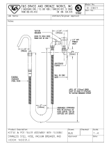
Drainage hole
U-Trap
B
C
A ≥ 70mm
B ≥ 2C
C ≥ 2 x SP
SP = External Pressure
(mmAq)
Ex) External Pressure
= 10mmAq
A ≥ 70mm
B ≥ 40mm
C ≥ 20mm
A
Make sure to be closed.
Unit
Drainage pipe
(Local supply)
Thermal insulator
(Local supply)
Installation of Indoor, Outdoor Unit
• Always lay the drain with downward
inclination (1/50 to 1/100).
Prevent any upward flow or reverse flow
in any part.
• 5mm or thicker formed thermal insulator
shall always be provided for the drain
pipe.
Lay the drain hose with a downward inclination so water will drain out.
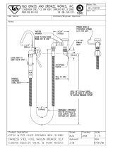
• Install the P-Trap (or U-Trap) to prevent a
water leakage caused by the blocking of
intake air filter.
Applied U-Trap Dimension
CORRECT
INCORRECT
• Upward routing not
allowed
Caution for gradient of unit and drain piping
• Drill the piping hole with 70mm dia, hole
core drill.
• Piping hole should be slightly slant to the
outdoor side.
5~7mm
Indoor Outdoor
WALL

16 Air Conditioner
Installation of Indoor, Outdoor Unit
Insulate the joint and tubes completely.
All thermal insulation must comply with local requirement.
REFRIGERANT PIPE
• Insulate and tape the gas piping.
n After all workings are finished, check the working and operation.
• Air distribution Is the air circulation good?
• Drain Is the drainage smooth and no sweating?
• Gas leakage Is the piping connection correct?
• Wiring Is the wiring connection correct?
• Lock-bolt Is the lock-bolt of compressor loosened?
THERMAL INSULATION
TEST AND CHECK
Make sure that there is no clearance here.
Overlap with thermal
insulator for piping.
Thermal insulator for refrigerant pipe
(Local supply)
Thermal insulator for
piping(Local supply)
Hose clip for thermal insulator(Local supply)
Union for liquid pipe
Refrigerant pipe and thermal
insulator(Local supply)
Union for gas pipe
Thermal insulator for refrigerant pipe
(Local supply)
Hose clip for thermal insulator
(Local supply)
Power cable
Thermal insulator
Gas pipe
Liquid pipe
Tape
Insulation, others

Installation Manual 17
ENGLISH
Installation of Indoor, Outdoor Unit
Install the remote control box and cord correctly.
• Although the room temperature sensor is in the indoor unit, the remote control box should
be installed in such places away from direct sunlight and high humidity.
INSTALLATION OF THE REMOTE CONTROL BOX
• Select places that is not splashed by water.
• Select control position after receiving
customer approval.
• The room temperature sensor of the
thermostat for temperature control is built in
the indoor unit.
• This remote controller equipped with liquid
crystal display. If this position is higher or
lower, display is difficult to see.
(The standard height is 1.2~1.5m high)
ROUTING OF THE REMOTE CONTROL CORD
• Keep the remote control cord away from
the refrigerant piping and the drain piping.
• To protect the remote control cord from
electrical noise, place the cord at least 5cm
away from other power cables. (Audio
equipment, Television set, etc)
• If the remote control cord is secured to a
wall, provide a trap at the top of the cord to
prevent water droplets from running.
POINT OF REMOTE CONTROLLER INSTALLATION
DISASSEMBLING OF THE REMOTE CONTROLLER
ELECTRICAL WIRING TO THE INDOOR UNIT
Make sure that wire and terminal
numbers are matched on unit side
and remote controller side.
(Main board)
CN REMO
The maximum length of the cord is 100m.
If the length of the cord exceeds 50m, use a wire size greater than 0.5mm
2
.
Remote controller
CN REMO
Remote
control
box body
Lever carefully
the box open
using a screw
driver, etc.
Front case
The lower part
Face of wall
Upper notch
Upper flange
Under plate
Remote
control cord
Remote
control unit
Tapping screw
(Local supply)
Lower notch
Face of wall
Upper notch
Lower notch
Switch box
(Local supply)
Under plate
Remote
control unit
Remote
control cord
Screw
(Local supply)
Cord
clamp
Push hand
(Part B)
(Part A)
FIXING OF REMOTE
CONTROL CORD
1. Fix the cord clamps on the wall
by ø3 tapping screws(Local supply).
2. Fix the remote control cord.
PROCEDURE OF INSTALLATION
1. Fix the under plate on the switch box by
screws(Local supply). In this case, fit the under
plate on the wall, and be careful of deformation.
2. Receive the remote control cord in the switch
box.
3. Hook the remote control unit on the under plate.
WHEN THE REMOTE CONTROL BOX IS
INSTALLED WITH THE CORD BURIED.
PROCEDURE OF INSTALLATION
1. Fix the under plate on the wall by self tapping
screws (accessory).
2. Make a slit (Part A) at the top side of the remote
control box by nipper.
3.Rout the cord as shown in the following figure. In
this case, push the cord into the around of
case(Part B).
4. Hook the remote control unit on the under plate.
WHEN THE REMOTE CONTROL BOX IS
INSTALLED WITH THE CORD EXPOSED.
installation of remote control box

18 Air Conditioner
Installation of Indoor, Outdoor Unit
• Since the room temperature sensor is in the remote controller, the remote controller box should be installed
in a place away from direct sunlight, high humidity and direct supply of cold air to maintain proper space
temperature.
Install the remote controller about 5ft(1.5m) above the floor in an area with good air circulation at an
average temperature.
Do not install the remote controller where it can be affected by:
- Drafts, or dead spots behind doors and in corners.
- Hot or cold air from ducts.
- Radiant heat from sun or appliances.
- Concealed pipes and chimneys.
- Uncontrolled areas such as an outside wall behind the remote controller.
- This remote controller is equipped with a seven segment LED. display. For proper display of the remote
controller LED's, the remote controller should be installed properly as shown in Fig.1.
(The standard height is 1.2~1.5 m from floor level.)
Operation unit
ZONE
1234
Humidify
JET
AUTO
AUTO SWING OPERATION
FAN SPEED
Program set
SUB FUNCTION
SET TEMP
Room Temp
HI
MED
LO
Heater
Defrost
Filter
Preheat
Out door
Time
Timer
On
Set no. Time
Off
01 03 05 07 09 11 13 15 17 19 21 23
O
p
era
tion
unit
Z
O
N
E
1
2
3
4
H
u
m
i
d
i
f
y
J
E
T
A
U
T
O
A
U
T
O
S
W
I
N
G
O
P
E
R
A
T
I
O
N
FA
N
S
P
E
E
D
P
rogr
am
s
et
S
U
B
F
U
N
C
T
I
O
N
S
E
T
T
E
M
P
R
o
o
m
T
e
m
p
H
I
M
E
D
L
O
H
e
a
t
e
r
D
e
f
r
o
s
t
F
i
l
t
e
r
P
r
e
h
e
a
t
O
u
t
d
o
o
r
T
im
e
T
im
e
r
O
n
S
e
t
n
o
.
T
i
m
e
O
f
f
0
1
0
3
0
5
0
7
0
9
1
1
1
3
1
5
1
7
1
9
2
1
2
3
5feet
(1.5meters)
no
no
no
yes
Operation unit
ZONE
1234
Humidify
JET
AUTO
AUTO SWING OPERATION
FAN SPEED
Program set
SUB FUNCTION
SET TEMP
Room Temp
HI
MED
LO
Heater
Defrost
Filter
Preheat
Out door
Time
Timer
On
Set no. Time
Off
01 03 05 07 09 11 13 15 17 19 21 23
Fig.1 Typical locations for remote controller
• Remove the control box cover for electrical
connection between the indoor and outdoor
unit.
(Remove screws ¿.)
• Use the cord clamper to fix the cord.
WIRING CONNECTION
Control terminal board
Control box
Control box cover
(On which the Electric
Wiring Connection is put)
AA
view
Remote
control cord
Connection
cord between
the indoor unit
and the
outdoor unit
Cord clamper
1
1
Wired remote controller installation

Installation Manual 19
ENGLISH
Installation of Indoor, Outdoor Unit
Ceiling Cassette Type
• Select and mark the position for fixing bolts
and piping hole.
• Decide the position for fixing bolts slightly tilted
to the drain direction after considering the
direction of drain hose.
• Drill the hole for anchor bolt on the wall.
• The hole size for four anchor bolts is Ø14.5mm
& 40mm depth.
CAUTION
•
This air-conditioner uses a drain pump.
• Horizontly install the unit using a level
gauge.
•
During the installation, care should be
taken not to damage electric wires.
• The dimensions of the paper model for installing are the same as those of the ceiling opening dimensions.
Ceiling board
Level gauge
Ceiling
Unit:mm
744 Unit size
744 Unit size
658 (Hanging bolt)
6666
790 (Ceiling opening)
790 (Ceiling opening)
572(Hanging bolt)
109
109
Unit:mm
570 Unit size
570 Unit size
450 (Hanging bolt)
7575
600 (Ceiling opening)
600 (Ceiling opening)
521(Hanging bolt)
39.5
39.5
Unit:mm
840 Unit size
840 Unit size
672 (Hanging bolt)
101.5101.5
875 (Ceiling opening)
875 (Ceiling opening)
785 (Hanging bolt)
45
45
TE
TF
TD

20 Air Conditioner
Installation of Indoor, Outdoor Unit
Set screw of
paper model (4 pieces)
Keep the length of *( )mm between
the air conditioner bottom surface
and the ceiling surface
Paper model
for installation
Ceiling board
150mm
Adjust the same height
Ceiling board
Ceiling
Flat washer for M10
(accessory)
Keep the length of the bolt
from the bracket to 40mm
Open the ceiling board
along the outer edge of the
paper model
Flat washer for M10
(accessory)
Hanging bolt
(W3/8 or M10)
Nut
(W3/8 or M10)
Nut
(W3/8 or M10)
Spring washer
(M10)
Air Conditioner body
n The Indoor Unit Installation
2. Avoid installing air conditioner in such circumstances where cutting oil mist or iron powder is in
suspension in factories, etc.
3. Avoid places where inflammable gas is generated, flows in, is stored or vented.
4. Avoid places where sulfurous acid gas or corrosive gas is generated.
5. Avoid places near high frequency generators.
*( ) → TQ/TR : 31~34mm
TP/TN/TM : 15mm
• Thoroughly study the following installation locations:
1. In such places as restaurants and kitchens, considerable amount of oil steam and flour
adhere to the turbo fan, the fin of the heat exchanger and the drain pump, resulting in heat
exchange reduction, spraying, dispersing of water drops, drain pump malfunction, etc.
In these cases, take the following actions:
• Make sure that the ventilation fan for smoke-collecting hood on a cooking table has sufficient
capacity so that it draws oily steam which should not flow into the suction of the air
conditioner.
• Make enough distance from a cooking room to install the air conditioner in such a place
where it may not suck in oily steam.
NOTICE
Use the ventilation fan
for smoke-collecting
hood with sufficient
capacity.
Cooking table
Air conditioner
Take enough
distance
/