LG MULTI V B1 Series Installation guide

Category
Split-system air conditioners
Type
Installation guide
System
Heat Pump Indoor Unit
INSTALLATION MANUAL
LG
MODELS: B1/B2 Series
Type: Ceiling Concealed Duct - Low Static
IMPORTANT
• Please read this installation manual completely before
installing the product.
• Installation work must be performed in accordance with
the national wiring standards by authorized personnel
only.
• Please retain this installation manual for future reference
after reading it thoroughly.
ENGLISH ITALIANO ESPAÑOL FRANÇAIS DEUTSCH
2 Indoor Unit
Ceiling Concealed Duct - Low Static Type Indoor Unit Installation Manual
TABLE OF CONTENTS
Four type "A" screws
Connecting cable
Pipes: Gas side
Liquid side
(Refer to Product Data)
Insulation materials
Additional drain pipe
Level gauge
Screw driver
Electric drill
Hole core drill
Flaring tool set
Specified torque wrenches
(different depending on model No.)
Spanner.......Half union
A glass of water
Screw driver
Hexagonal wrench
Gas-leak detector
Vacuum pump
Gauge manifold
Owner's manual
Thermometer
Safety Precautions.................3
Introduction.............................6
Installation
Selection of the best location
................................................7
Ceiling opening dimension
and hanging bolt location......8
Indoor Unit Installation...........9
Wiring Connection.................9
Part name and functions.....10
Checking the Drainage........11
Two Thermistor system.......16
E.S.P.(External Static
Pressure) Setting.................17
How to Set E.S.P?...............18
Installation Requirements
Required Parts Required Tools
Installation Manual 3
ENGLISH
Safety Precautions
Safety Precautions
To prevent injury to the user or other people and property damage, the following instructions must be followed.
Be sure to read before installing the air conditioner.
Be sure to observe the cautions specified here as they include important items related to safety.
Incorrect operation due to ignoring instruction will cause harm or damage. The seriousness is classified by the
following indications.
Meanings of symbols used in this manual are as shown below.
This symbol indicates the possibility of death or serious injury.
This symbol indicates the possibility of injury or damage to properties only.
Be sure not to do.
Be sure to follow the instruction.
Installation
Do not use a defective or under-
rated circuit breaker. Use this
appliance on a dedicated circuit.
• There is risk of fire or electric shock.
For electrical work, contact the
dealer, seller, a qualified electri-
cian, or an Authorized Service
Center.
• Do not disassemble or repair the
product. There is risk of fire or elec-
tric shock.
Always ground the product.
• There is risk of fire or electric shock.
Install the panel and the cover
of control box securely.
• There is risk of fire or electric shock.
Always install a dedicated cir-
cuit and breaker.
• Improper wiring or installation may
cause fire or electric shock.
Use the correctly rated breaker
or fuse.
• There is risk of fire or electric shock.
4 Indoor Unit
Safety Precautions
Operation
Do not modify or extend the
power cable.
• There is risk of fire or electric shock.
Do not let the air conditioner
run for a long time when the
humidity is very high and a door
or a window is left open.
• Moisture may condense and wet or
damage furniture.
Be cautious when unpacking
and installing the product.
• Sharp edges could cause injury. Be
especially careful of the case edges
and the fins on the condenser and
evaporator.
For installation, always contact
the dealer or an Authorized
Service Center.
• There is risk of fire, electric shock,
explosion, or injury.
Do not install the product on a
defective installation stand.
• It may cause injury, accident, or
damage to the product.
Be sure the installation area
does not deteriorate with age.
• If the base collapses, the air condi-
tioner could fall with it, causing prop-
erty damage, product failure, and
personal injury.
Do not store or use flammable gas or combustibles near the product.
• There is risk of fire or failure of product.
Gasolin
Installation Manual 5
ENGLISH
Safety Precautions
Always check for gas (refriger-
ant) leakage after installation or
repair of product.
• Low refrigerant levels may cause
failure of product.
Install the drain hose to ensure
that water is drained away prop-
erly.
• A bad connection may cause water
leakage.
Keep level even when installing
the product.
• To avoid vibration or water leakage.
Do not install the product where
the noise or hot air from the out-
door unit could damage the
neighborhoods.
• It may cause a problem for your
neighbors.
Use two or more people to lift
and transport the product.
• Avoid personal injury.
Do not install the product where
it will be exposed to sea wind
(salt spray) directly.
It may cause corrosion on the product.
Corrosion, particularly on the con-
denser and evaporator fins, could
cause product malfunction or inefficient
operation.
90˚
Installation
6 Indoor Unit
Introduction
Introduction
Air outlet vents
Air filters
Remote Controller
This symbol alerts you to the risk of electric shock.
This symbol alerts you to hazards that could cause harm to the
air conditioner.
This symbol indicates special notes.
NOTICE
Symbols Used in this Manual
Features
B1/B2 Series : Low static Duct type
Installation Manual 7
ENGLISH
Installation
Installation
Indoor unit
Install the air conditioner in the location that satisfies the fol-
lowing conditions.
The place shall easily bear a load exceeding four times the
indoor units weight.
The place shall be able to inspect the unit as the figure.
The place where the unit shall be leveled.
The place shall easily connect with the outdoor unit.
The place where the unit is not affected by an electrical
noise.
The place where air circulation in the room will be good .
There should not be any heat source or steam near the
unit
Confirm the positional relationship between the unit and
suspension bolts.
Installation the ceiling opening to clean the filter or service
under the product.
Selection of the best location
Inspection hole
(600 x 600)
Control box
H=20 or more
Suitable dimension "H" is necessary to get a slooe
to drain as aiven in the fiaure
Side view
(unit: mm)
600600
A(Min)
B(Min)
Ceiling
Service Space
A
B
Model A B
7/9/12k 600 900
18/24k 600 1100
(Length: mm)
B1/B2 Series : Low static Duct type
8 Indoor Unit8 Indoor Unit
Installation
Ceiling dimension and hanging bolt location
Installation of Unit
Install the unit above the ceiling correctly.
Apply a joint-canvas between the unit and duct to absorb
unnecessary vibration.
Apply a filter Accessory at air return hole.
Install the unit leaning to a drainage hole side as a figure
for easy water drainage.
A place where the unit will be leveled and that can support
the weight of the unit.
A place where the unit can withstand its vibration.
A place where service can be easily performed.
CASE 1
POSITION OF SUSPENSION BOLT
(Unit:mm)
7/9/12k BTU/h
850 900 383 575 93 190 21 795 163 820
18/24k BTU/h 1130 1180 383 575 93 190 21 1065 163 1100
Dimension
Capacity
ABCDEFGHI J
CE
G
D
A
J
B
M10 Nut
M10 SP. washer
M10 washer
X 4
X 4
(Local
supply)
X 4
M10 Nut
M10 SP. washer
M10 washer
X 4
X 4
(Local
supply)
X 4
I
F
H
Drainage hole
Drain Pump use
CASE 2
POSITION OF CONSOLE BOLT
Installation Manual 9
ENGLISH
Installation
Select and mark the position for fixing bolts.
Drill the hole for set anchor on the face of ceiling.
Insert the set anchor and washer onto the suspen-
sion bolts for locking the suspension bolts on the
ceiling.
Mount the suspension bolts to the set anchor firmly.
Secure the installation plates onto the suspension
bolts (adjust level roughly) using nuts, washers
and spring washers.
1 Set anchor
Old building New building
2 Plate washer
3 Spring washer
4 Nut
5 Suspension
bolts
Connect the wires to the terminals on the control board individually according to the outdoor unit connection.
Ensure that the color of the wires of outdoor unit and the terminal No. are the same as those of indoor unit respectively.
Terminal Block Indoor
1(L) 2(N) 3 4
INDOOR POWER INPUT
Indoor
unit
Outdoor
unit
Central
controller
A
B E F C D Vcc GND
Main
outdoor unit
Wiring Connection
Indoor Unit Installation
CAUTION : Tighten the nut and bolt
to prevent unit falling.
WARNING : Make sure that the screws of the terminal are free from looseness.
B1/B2 Series
10 Indoor Unit10 Indoor Unit
Installation
Low static duct type in case of suction from back
side.
Low static duct type in case of suction from bottom
side.
Air Filter
Air outlet
Panel Rear
Air outlet
Air Filter
Panel Rear
Part name and functions
Installation Manual 11
ENGLISH
Installation
1. Remove the Air Filter.
2. Check the drainage.
Spray one or two glasses of water upon the
evaporator.
Ensure that water flows drain hose of indoor
unit without any leakage.
Checking the Drainage
INSULATION, OTHERS
Insulate the joint and tubes completely.
All thermal insulation must comply with local requirement.
INDOOR UNIT
After all workings are finished, check the working and operation.
Air distribution............... Is the air circulation good?
Drain ............................. Is the drainage smoothly and no sweating?
Gas leakage ................. Is the piping connection correctly?
Wiring ........................... Is the wiring connection correctly?
Lock-bolt ....................... Is the lock-bolt of compressor loosened?
Insulation Is the unit fully insulated?
Ground Is the unit safely grounded?
THERMAL INSULATION
TEST AND CHECK
Make sure that there is no clearance here.
Overlap with thermal
insulator for piping.
Thermal insulator for refrigerant pipe
(Local supply)
Thermal insulator for
piping(Local supply)
Hose clip for thermal insulator(Local supply)
Union for gas pipe
Refrigerant pipe and thermal
insulator(Local supply)
Union for liquid pipe
Thermal insulator for refrigerant pipe
(Local supply)
Hose clip for thermal insulator
(Local supply)
Felt
Rubber
Insulation
No clearance
Cabinet
12 Indoor Unit12 Indoor Unit
Installation
Front of view
1. Install declination of the indoor unit is very important for the drain of the duct type air conditioner.
2. Minimum thickness of the insulation for the connecting pipe shall be 19mm.
The unit must be horizontal or declined to the drain hose connected when finished
installation.
Drain piping must have down-slope (1/50 to 1/100): be sure not to
provide up-and-down slope to prevent reversal flow.
During drain piping connection, be careful not to exert extra force
on the drain port on the indoor unit.
The outside diameter of the drain connection on the indoor unit is
32mm.
Be sure to install heat insulation on the drain piping.
Piping material: Polyvinyl chloride pipe VP-25 and
pipe fittings
The air conditioner uses a drain pump to drain water.
Use the following procedure to test the drain pump operation:
Connect the main drain pipe to the exterior
and leave it provisionally until the test
comes to an end.
Feed water to the flexible drain hose and
check the piping for leakage.
Be sure to check the drain pump for normal
operating and noise when electrical wiring
is complete.
When the test is complete, connect the
flexible drain hose to the drain port on the
indoor unit.
Heat insulation material: Polyethylene foam with thick-
ness more than 8 mm.
Drain test
Upward
routing
not allowed
Pipe clamp
1/50~1/100
MAX 700mm
Flexible drain hose
Maintenance
drain port
Indoor unit
Feed water
Drain Pump
Drain pan
Flexible drain hose
Main
drain pipe
Glue the joint
Drain
port
Drain hose connection
Use the clip
Flexible drain hose
Drain Piping
Installation Manual 13
ENGLISH
Installation
CAUTION:
After the confirmation of the above conditions, prepare the wiring as follows:
1) Never fail to have an individual power specialized for the air conditioner. As for the method of
wiring, be guided by the circuit diagram posted on the inside of control box cover.
2) Provide a circuit breaker switch between power source and the unit.
3) The screws which fasten the wiring in the casing of electrical fittings are liable to come loose
from vibrations to which the unit is subjected during the course of transportation. Check them
and make sure that they are all tightly fastened. (If they are loose, it could give rise to burn-out
of the wires.)
4) Specification of power source
5) Confirm that electrical capacity is sufficient.
6) Be sure that the starting voltage is maintained at more than 90 percent of the rated voltage
marked on the name plate.
7) Confirm that the cable thickness is as specified in the power sources specification.
(Particularly note the relation between cable length and thickness.)
8) Never fail to equip a leakage breaker where it is wet or moist.
9) The following troubles would be caused by voltage drop-down.
Vibration of a magnetic switch, damage on the contact point, fuse breaking, disturbance by the nor-
mal function of an overload protection device.
Proper starting power is not given to the compressor.
HAND OVER
Teach the customer the operation and maintenance procedures, using the operation manual.
(air filter cleaning, temperature control, etc.)
1/50~1/100
MAX 700mm
Flexible drain hoseFlexible drain hoseFlexible drain hose
CAUTION : The supplied flexible drain
hose should not be curved, neither
screwed. The curved or screwed hose
may cause a leakage of water.
14 Indoor Unit14 Indoor Unit
Installation
INSTALLATION OF REMOTE CONTROL BOX
Install the remote control box and cord correctly.
Although the room temperature sensor is in the indoor unit, the remote control box should be installed
in such places away from direct sunlight and high humidity.
INSTALLATION OF THE REMOTE CONTROL BOX
Select places that is not splashed by water.
Select control position after receiving customer
approval.
The room temperature sensor of the thermostat
for temperature control is built in the indoor
unit.
This remote controller equipped with liquid
crystal display. If this position is higher or
lower, display is difficult to see.
(The standard height is 1.2~1.5m high)
ROUTING OF THE REMOTE CONTROL CORD
Keep the remote control cord away from the
refrigerant piping and the drain piping.
To protect the remote control cord from electri-
cal noise, place the cord at least 5cm away
from other power cables. (Audio equipment,
Television set, etc)
If the remote control cord is secured to a wall,
provide a trap at the top of the cord to prevent
water droplets from running.
POINT OF REMOTE CONTROLLER INSTALLATION
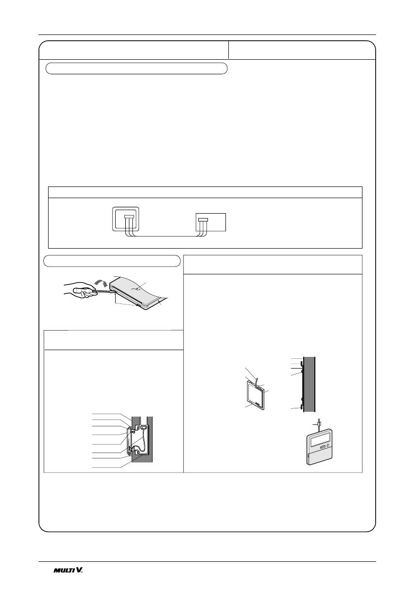
DISASSEMBLING OF THE REMOTE CONTROLLER
ELECTRICAL WIRING TO THE INDOOR UNIT
Make sure that wire and terminal
numbers are matched on unit side
and remote controller side.
(Main board)
CN REMO
The maximum length of the cord is 100m.
If the length of the cord exceeds 50m, use a wire size greater than 0.5mm
2
.
Remote controller
CN REMO
Remote
control
box body
Lever carefully
the box open
using a screw
driver, etc.
Front case
The low
er part
Face of wall
Upper notch
Upper flange
Under plate
Remote
control cord
Remote
control unit
Tapping screw
(Local supply)
Lower notch
Face of wall
Upper notch
Lower notch
Switch box
(Local supply)
Under plate
Remote
control unit
Remote
control cord
Screw
(Local supply)
Cord
clamp
Push hand
(Part B)
(Part A)
FIXING OF REMOTE
CONTROL CORD
1. Fix the cord clamps on the wall
by ø3 tapping screws(Local supply).
2. Fix the remote control cord.
PROCEDURE OF INSTALLATION
1. Fix the under plate on the switch box by
screws(Local supply). In this case, fit the under
plate on the wall, and be careful of deformation.
2. Receive the remote control cord in the switch box.
3. Hook the remote control unit on the under plate.
WHEN THE REMOTE CONTROL BOX IS
INSTALLED WITH THE CORD BURIED.
PROCEDURE OF INSTALLATION
1. Fix the under plate on the wall by self tapping screws
2. Make a slit (Part A) at the top side of the remote control
box by nipper.
3. Rout the cord as shown in the following figure. In this
case, push the cord into the around of case(Part B).
4. Hook the remote control unit on the under plate.
WHEN THE REMOTE CONTROL BOX IS INSTALLED
WITH THE CORD EXPOSED.
Installation Manual 15
ENGLISH
Installation
WIERED REMOTE CONTROLLER INSTALLATION
Since the room temperature sensor is in the remote controller, the remote controller box should be installed in a place
away from direct sunlight, high humidity and direct supply of cold air to maintain proper space temperature.
Install the remote controller about 5ft(1.5m) above the floor in an area with good air circulation at an average tempera-
ture.
Do not install the remote controller where it can be affected by:
- Drafts, or dead spots behind doors and in corners.
- Hot or cold air from ducts.
- Radiant heat from sun or appliances.
- Concealed pipes and chimneys.
- Uncontrolled areas such as an outside wall behind the remote controller.
- This remote controller is equipped with a seven segment LED. display. For proper display of the remote controller
LED's, the remote controller should be installed properly as shown in Fig.1.
(The standard height is 1.2~1.5 m from floor level.)
Operation unit
ZONE
1234
Humidify
JET
AUTO
AUTO SWING OPERATION
FAN SPEED
Program set
SUB FUNCTION
SET TEMP
Room Temp
HI
MED
LO
Heater
Defrost
Filter
Preheat
Out door
Time
Timer
On
Set no.Time
Off
01 03 05 07 0911 13 15 1719 21 23
O
p
e
r
a
t
i
o
n
u
n
i
t
Z
O
N
E
1
2
3
4
H
u
m
i
d
i
f
y
J
E
T
A
U
T
O
A
U
T
O
S
W
IN
G
O
P
E
R
A
T
IO
N
F
A
N
S
P
E
E
D
P
r
o
g
r
a
m
s
e
t
S
U
B
F
U
N
C
T
I
O
N
S
E
T
T
E
M
P
R
o
o
m
T
e
m
p
H
I
M
E
D
L
O
H
e
a
t
e
r
D
e
f
r
o
s
t
F
i
l
t
e
r
P
r
e
h
e
a
t
O
u
t
d
o
o
r
T
i
m
e
T
i
m
e
r
O
n
S
e
t
n
o
.
T
i
m
e
O
f
f
0
1
0
30
5
0
7
0
9
1
1
1
3
1
5
1
7
1
9
2
1
2
3
5feet
(1.5meters)
no
no
no
yes
Operation unit
ZONE
1234
Humidify
JET
AUTO
AUTO SWING OPERATION
FAN SPEED
Program set
SUB FUNCTION
SET TEMP
Room Temp
HI
MED
LO
Heater
Defrost
Filter
Preheat
Out door
Time
Timer
On
Set no.Time
Off
01 03 05 07 0911 13 15 1719 21 23
Fig.1 Typical locations for remote controller
16 Indoor Unit16 Indoor Unit
Two Thermistor system
Open the rear cover of Remote Controller to set up the
mode.
Selectable options are three as follows.
- Remo: Sensing the room Temperature.
- Indoor Unit: Sensing the intake air into indoor Unit.
- 2 TH: Sensing the lower temperature of the two thermis-
tors.
To set up the mode, adjust the slide switch to desired
mode position on installing.
Slide Switch1
Remo.
Room Temp. Sensing
Indoor Unit
2 TH(Remo.+Indoor)
On installing, don't impact to the PCB
and LCD display.
Don't remove the protection sheet.
Use the specified screw.
On installing, turn off the main power.
CAUTION
Single
Group
Slide Switch2
Two Thermistor system
Installation Manual 17
ENGLISH
E.S.P.(External Static Pressure) Setting
Open the rear cover of the wired remote-controller to set the mode.
Select one of three selectable modes as follows.
Without Zone System
1. Position V-H, F-H:
This position sets the maximum E.S.P as a default set.
2. Position V-L:
This position sets the minimum E.S.P as a default set.
With Zone System
1. Position V-H:
Maximum E.S.P setting & Fan speed is varied according to the state of dampers by micom.
2. Position F-H:
Maximum E.S.P setting & Fan speed doesn't vary according to the opening & Closing of dampers.
3. Position V-L:
Minimum E.S.P setting & Fan speed is varied according to the state of dampers by micom.
*Maximum: 9K/12K-8mmAq
Minimum: All-0mmAq
Move the slide switch to set position.
Close the rear cover and check if it works normally.
CAUTION:
Select the position after checking duct work and E.S.P of the unit.
Maunfactured in the position F-H.
TH
R14H
SW TH
REMO
MAIN
2TH
OP7
R18H
R17H
OP6
LO
STAND
SW HIGH
HI
R03S
C070
R04S
R02S
R01S
OP3
OP2 OP1
R19H
R11H
R13H R12H
OP5R16H OP4
R15H
CO1H
V-L
V-H
F-H
Slide switch for ceiling height
18 Indoor Unit18 Indoor Unit
How to Set E.S.P?
How to Set E.S.P?
Procedure of RPM change:
Ex) External Static pressure is 4mmAq for Model Name "ARNU12GB1G1, ARNU24GB2G1"
To protect the unit, compressor is designed to be off during E.S.P. setting.
Preheat
ZONE
Operation unit Program set
Room Temp
MED
LO
AUTO
JET
Heater
Defrost
Filter
Humidify
Out door
Timer
On
Set no. Time
Off
01 03 05 07 09 11 13 15 17 19 21 23
1234
OPERATION
FAN SPEED
SUB FUNCTION
SET TEMP
HI
AUTO SWING
Time
Preheat
ZONE
Operation unit Program set
Room Temp
MED
LO
AUTO
JET
Heater
Defrost
Filter
Humidify
Out door
Timer
On
Set no. Time
Off
01 03 05 07 09 11 13 15 17 19 21 23
1234
OPERATION
FAN SPEED
SUB FUNCTION
SET TEMP
HI
AUTO SWING
Time
Time
SUB FUNCTION
SET TEMP
OPERATIONAUTO SWING
Preheat
ZONE
Operation unit Program set
Room Temp
MED
LO
AUTO
JET
Heater
Defrost
Filter
Humidify
Out door
Timer
On
Set no. Time
Off
01 03 05 07 09 11 13 15 17 19 21 23
1234
FAN SPEED
HI
2
Time
SUB FUNCTION
SET TEMP
OPERATIONAUTO SWING
Preheat
ZONE
Operation unit Program set
Room Temp
MED
LO
AUTO
JET
Heater
Defrost
Filter
Humidify
Out door
Timer
On
Set no. Time
Off
01 03 05 07 09 11 13 15 17 19 21 23
34
FAN SPEED
HI
1
Timer
1
2
3
5
4
Timer
Push the "On/Off" button.
The unit will start.
Push the "Timer" and "Wind" button simultaneously for more then 3 seconds.
Push the "Up" of "Down" button for E.S.P adjustment.
And, adjust the number which you want.(In this example, the number is "190". Refer to the
table 1 or 2 on the next page.)
Shift the fan speed mode by pressing the fan speed button.
And then, Adjust numbers of next steps by repeating the stage 3.
(In this example, the numbers are "220" and "235" respectly)
Push the "Timer" and "Wind" button simultaneously for more than 3 seconds.
Then, Wind Data is memorized by the EEPROM of the main PCB.
The range of selection is from 1~254. Since, the display is two Digit only.
If the range selection is above 100 then the third digit will appear in the screen as shown.
NOTICE
Installation Manual 19
ENGLISH
How to Set E.S.P?
[Table.1] B1/B2 Series
Static Pressure(mmAq) 0 1 2 3 4
Model Name
Step(Hi/Med/Lo)
Setting Value
8.5CMM 75 84 94 103 114
7k 7.5CMM 69 77 88 99 110
6.5CMM 62 71 83 95 106
9.5CMM 82 90 99 109 118
9k 8.5CMM 75 84 94 104 114
7.5CMM 69 77 88 99 110
10.5CMM 89 96 103 113 122
12k 9.5CMM 82 90 99 109 118
8.5CMM 75 84 94 104 114
16CMM 95 103 110 117 125
18k 14CMM 84 93 101 109 117
12CMM 75 84 93 103 113
19CMM 110 117 125 129 -
24k 17CMM 100 107 115 115 127
15CMM 90 97 105 114 122
20 Indoor Unit20 Indoor Unit
Memo
  • Page 1 1
  • Page 2 2
  • Page 3 3
  • Page 4 4
  • Page 5 5
  • Page 6 6
  • Page 7 7
  • Page 8 8
  • Page 9 9
  • Page 10 10
  • Page 11 11
  • Page 12 12
  • Page 13 13
  • Page 14 14
  • Page 15 15
  • Page 16 16
  • Page 17 17
  • Page 18 18
  • Page 19 19
  • Page 20 20

LG MULTI V B1 Series Installation guide

Category
Split-system air conditioners
Type
Installation guide

Ask a question and I''ll find the answer in the document

Finding information in a document is now easier with AI