Page is loading ...

Save this manual for future reference.
VENT-FREE PROPANE GAS HEATER
OWNER’S OPERATION AND INSTALLATION MANUAL
®
G
I
D
E
S
I
N
N
A
E
S
T
D
C
E
R
T
I
I
F
I
E
A
M
C
R
A
S
O
C
I
A
O
N
®
GS
A
Models: VP5A and VP11
WARNING: Improper installation,
adjustment, alteration, service, or
maintenance can cause injury or
property damage. Refer to this
manual for correct installation and
operational procedures. For assis-
tance or additional information
consult a qualified installer, ser-
vice agency, or the gas supplier.
WARNING: If the information in this manual
is not followed exactly, a fire or explosion
may result causing property damage, per-
sonal injury, or loss of life.
— Do not store or use gasoline or other
flammable vapors and liquids in the
vicinity of this or any other appliance.
— WHAT TO DO IF YOU SMELL GAS
• Do not try to light any appliance.
• Do not touch any electrical switch; do
not use any phone in your building.
• Immediately call your gas supplier from
a neighbor’s phone. Follow the gas
supplier’s instructions.
• If you cannot reach your gas supplier,
call the fire department.
— Installation and service must be per-
formed by a qualified installer, service
agency, or the gas supplier.

2
CONTENTS
SECTION PAGE
Safety Information.........................................................................2
Product Identification .................................................................... 4
Local Codes ...................................................................................4
Unpacking......................................................................................4
Product Features ............................................................................ 4
Installing To Wall..........................................................................5
Connecting To Gas Supply............................................................9
Checking Gas Connections............................................................10
Operating Heater ...........................................................................12
Inspecting Burner ..........................................................................15
Cleaning And Maintenance ........................................................... 16
Troubleshooting.............................................................................17
Technical Service ..........................................................................20
Specifications ................................................................................ 20
Service Hints ................................................................................. 21
Replacement Parts .........................................................................21
Service Publications ...................................................................... 21
Accessory ......................................................................................21
Parts List (Model VP5A)...............................................................22
Illustrated Parts Breakdown (Model VP5A) ................................. 22
Parts List (Model VP11)................................................................23
Illustrated Parts Breakdown (Model VP11) ..................................23
Warranty Information ....................................................................Back Cover
Safety Information continued on next page
SAFETY
INFORMATION
!
WARNING ICON G 001
WARNINGS
IMPORTANT: Read this Owner’s Manual carefully and completely
before trying to assemble, operate, or service this heater. Improper
use of this heater can cause serious injury or death from burns, fire,
explosion, and carbon monoxide poisoning.
!
WARNING ICON G 001
DANGER
Carbon monoxide poisoning may lead to death!
Carbon Monoxide Poisoning: Early signs of carbon monoxide poisoning
resemble the flu, with headaches, dizziness, or nausea. If you have these signs, the
heater may not be working properly. Get fresh air at once! Have heater serviced.
Some people are more affected by carbon monoxide than others. These include
pregnant women, persons with heart or lung disease or anemia, those under the
influence of alcohol, and those at high altitudes.
Propane Gas: Propane gas is odorless. An odor-making agent is added to
propane gas. The odor helps you detect a propane gas leak. However, the odor
added to propane gas can fade. Propane gas may be present even though no odor
exists.
Make certain you read and understand all Warnings. Keep this manual for
reference. It is your guide to safe and proper operation of this heater.

3
SAFETY
INFORMATION
Continued
!
WARNING ICON G 001
WARNINGS
Continued
1. Use only propane gas. Do not convert heater to use different fuel type.
2. Do not place propane supply tank(s) inside any structure. Locate propane
supply tank(s) outdoors.
3. If you smell gas
• shut off gas supply
• do not try to light any appliance
• do not touch any electrical switch; do not use any phone in your building
• immediately call your gas supplier from a neighbor’s phone. Follow the
gas supplier’s instructions
• if you cannot reach your gas supplier, call the fire department
4. Never install the heater
• in sleeping quarters, a mobile home, or a recreational vehicle
• where curtains, furniture, clothing, or other flammable objects are less than
36 inches from the front, top, or sides of the heater
• as a fireplace insert
• in high traffic areas
• in windy or drafty areas
5. Always run heater with control knob at LOW or HIGH locked positions
(VP11) or ON position (VP5A). Never set control knob between locked
positions. Poor combustion and higher levels of carbon monoxide may result.
6. Open window to admit fresh, outside air when using heater. Open window one
or two inches. When used without fresh, outside air, heater may give off
carbon monoxide gas.
7. Never run heater in small, closed room. Open door into next room to help
ventilate.
8. Keep all air openings in the front and bottom of heater clear and free of debris.
This will insure enough air for proper combustion.
9. If heater shuts off, do not relight until you provide fresh, outside air. If heater
keeps shutting off, have it serviced.
10.Do not run heater
• where flammable liquids or vapors are used or stored
• under dusty conditions
11.Never place any objects on the heater.
12.Surface of heater becomes very hot when running heater. Keep children and
adults away from hot surface to avoid burns or clothing ignition. Heater will
remain hot for a time after shut-down. Allow surface to cool before touching.
13.Make sure grill guard is in place before running heater.
14.Do not alter heater or its controls. Any change may create a safety hazard.
15.Do not use heater if any part of heater has been under water.
16.Turn off heater and let cool before servicing. Only a qualified service person
should service and repair heater.
17.Do not operate heater above elevations of 4,500 feet.

4
PRODUCT
IDENTIFICATION
PRODUCT
FEATURES
Safety Device
This heater has a pilot with an Oxygen Depletion Sensor Shutoff System (ODS).
The ODS/pilot is a required feature for vent-free room heaters. The ODS/pilot shuts
off the heater if there is not enough fresh air.
Piezo Ignition System
This heater has a piezo ignitor. This system requires no matches, batteries, or other
sources to light heater.
LOCAL CODES
Install and use heater with care. Follow all local codes. In the absence of local
codes, use the latest edition of National Gas Code ANSI Z223.1, also known as
NFPA 54*.
*Available from:
American National Standards Institute, Inc.
1430 Broadway
New York, NY 10018
National Fire Protection Association, Inc.
Batterymarch Park
Quincy, MA 02269
UNPACKING
1. Remove heater from carton.
2. Remove all protective packaging applied to heater for shipment.
3. Check heater for any shipping damage. If heater is damaged, promptly inform
dealer where you bought heater.
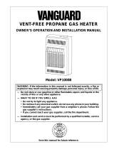
Control Knob
Heater
Cabinet
Grill
Guard
Burners
Front
Panel
Figure 1 - Vent-Free Propane Gas Heater (Model VP11 Shown)

5
INSTALLING
TO WALL
NOTICE
A qualified service person must install heater. Follow all local codes.
Continued
CHECK GAS TYPE
Use only propane gas. If your gas supply is not propane, do not install heater. Call
dealer where you bought heater for proper type heater.
INSTALLATION ITEMS
Before installing heater, make sure you have the items listed below.
• external regulator (supplied by
installer-see page 9)
• piping (check local codes)
• sealant (resistant to propane gas)
• manual shutoff valve *
• ground joint union
• test gauge connection * (see
Figure 11, page 10)
• sediment trap
• tee joint
• pipe wrench
* An A.G.A. design-certified manual shutoff valve with 1/8" NPT tap is an acceptable
alternative to test gauge connection. The optional A.G.A. design-certified manual
shutoff valve can be purchased from your dealer. See ACCESSORY, page 21.
LOCATING HEATER
This heater is designed to be mounted on a wall.
!
WARNING ICON G 001
WARNING
Maintain the minimum clearances shown in Figure 2 (page 6). If you
can, provide greater clearances from floor, ceiling, and joining wall.
!
WARNING ICON G 001
WARNING
Never install the heater
• in sleeping quarters, a mobile home, or a recreational vehicle
• where curtains, furniture, clothing, or other flammable objects
are less than 36 inches from the front, top, or sides of the heater
• as a fireplace insert
• in high traffic areas
• in windy or drafty areas
!
WARNING ICON G 001
CAUTION
Operating heater where impurities in the air (such as tobacco
smoke) exist, may discolor walls.
!
WARNING ICON G 001
CAUTION
If you install the heater in a home garage
• heater pilot and burner must be at least 18 inches above floor
• locate heater where moving vehicle will not hit it
For convenience and efficiency, install heater
• where there is easy access for operation, inspection, and service
• in coldest part of room

6
2. Mark two mounting screw locations on wall (see Figure 3).
INSTALLING HEATER TO WALL
Marking Screw Locations
1. Determine where you will locate heater.
Figure 3 - Mounting Screw Locations
Mounting
Screw
Locations
10 7/8"
Minimum To
Maintain 8"
Clearance
From Wall
7 3/4"
20 1/4"
Minimum To
Maintain 3"
Clearance
From Floor
Figure 2 - Mounting Clearances As Viewed From Front of Heater
FLOOR
JOINING WALL
36"
3"
FLOOR
CEILING
Minimum
Minimum To Top Surface
Of Carpeting, Tile Or Other
Combustible Material
8"
Minimum
From
Sides Of
Heater
Right
Side
Left
Side
!
WARNING ICON G 001
WARNING
Maintain minimum clearances shown in Figure 3. If you can,
provide greater clearances from floor and joining wall.

7
Installing Two Mounting Screws
Note:
Wall anchors and mounting screws are in hardware package. The hardware
package is provided with heater.
Attaching to wall stud method
For attaching mounting screw to wall stud
1. Drill hole at marked location using 9/64" drill bit.
2. Insert mounting screw into wall stud.
3. Tighten screw until 1/16" space (thickness of penny) is between screwhead and
wall.
Attaching to wall anchor method
Follow instructions below to attach mounting screws to hollow walls (wall areas
between studs) or solid walls (concrete or masonry).
1. Drill holes at marked locations using 5/16" drill bit. For solid walls (concrete or
masonry), drill at least 1 1/4" deep.
2. Fold wall anchor (see Figure 4).
ANCHOR
Figure 6 - Tightening Anchors
5. Tighten two screws until 1/16" space (thickness of penny) is between
screwheads and wall (see Figure 6).
Figure 5 - Popping Open Anchor Wings For Thin Walls
Thin Walls
(1/4" to 1/2" thick)
3. Insert wall anchor (wings first) into hole. Tap anchor flush to wall.
4. For thin walls (1/2" or less), insert red key into wall anchor. Push red key to
“pop” open anchor wings (see Figure 5).
IMPORTANT:
Do not hammer key!
For thick walls (over 1/2" thick) or solid walls, do not pop open wings.
Figure 4 - Folding Anchor
Thin or Thick Wall
(thick wall shown)
Solid Wall
1/16" Space

8
Placing Heater On Mounting Screws
1. Locate two keyhole slots on back panel of heater (see Figure 7).
2. Place large openings of slots over screwheads. Slide heater down until screws
are in small portion of slots.
Figure 9 - Installing Bottom Mounting Screw
Figure 7 - Location Of Keyhole Slots On Back Panel Of Heater
Keyhole Slots
Removing Front Panel Of Heater
1. Remove two screws near bottom corners of front panel.
2. Lift straight up on grill guard until it stops. Grill guard will slide up about 1/4".
3. Pull bottom of front panel forward, then down.
Figure 8 - Removing Front Panel Of Heater
Installing Bottom Mounting Screw
1. Locate bottom mounting hole. This hole is near bottom on back panel of heater
(see Figure 9).
2. Mark screw location on wall.
3. Remove heater from wall.
4. If installing bottom mounting screw into hollow or solid wall, install wall anchor.
Follow steps 1 through 5 under Attaching To Wall Anchor Method, page 7.
If installing bottom mounting screw into wall stud, drill hole at marked location
using 9/64" drill bit.
5. Replace heater on wall.
6. Insert bottom anchor screw through back panel into bottom anchor or drilled
hole (see Figure 9).
7. Tighten screw until heater is firmly secured to wall. Do not over tighten.
Note:
Do not replace front panel at this time. Replace front panel after making
gas connections and checking for leaks (see pages 9-11).

9
CONNECTING
TO GAS
SUPPLY
NOTICE
A qualified service person must connect heater to gas supply.
Follow all local codes.
The installer must supply an external regulator. The external regulator will reduce
incoming gas pressure. You must reduce incoming gas pressure to between 11 and
14 inches of water. If you do not reduce incoming gas pressure, heater regulator
damage could occur. Install external regulator with the vent pointing down as
shown in Figure 10. Pointing the vent down protects it from freezing rain or sleet.
!
WARNING ICON G 001
CAUTION
Never connect heater directly to the propane supply. This heater
requires an external regulator (not supplied). Install the external
regulator between the heater and propane supply.
Continued
Install sediment trap in supply line as shown in Figure 11. Locate sediment trap
where it is within reach for cleaning. Locate sediment trap where trapped matter is
not likely to freeze. A sediment trap traps moisture and contaminants. This keeps
them from going into heater controls. If sediment trap is not installed or is installed
wrong, heater may not run properly.
!
WARNING ICON G 001
CAUTION
Use pipe joint sealant that is resistant to liquid petroleum (LP) gas.
Installation must include a manual shutoff valve, ground joint union, and plugged
1/8" NPT tap. Locate NPT tap within reach for test gauge hook up. NPT tap must
be upstream from heater (see Figure 11, page 10).
Apply pipe joint sealant lightly to male threads. This will prevent excess sealant
from going into pipe. Excess sealant in pipe could result in clogged heater valves.
Figure 10 - External Regulator With Vent Pointing Down
!
WARNING ICON G 001
CAUTION
Use only new, black iron or steel pipe. Copper tubing may be used
in certain areas. Check your local codes. Use pipe 3/8" diameter or
greater to allow proper gas volume to heater. If pipe is too small,
undue loss of pressure will occur.
Propane
Supply Tank
Vent Pointing
Down
External
Regulator

10
IMPORTANT:
Hold pressure regulator with wrench when connecting it to gas piping
and/or fittings.
Figure 11 - Gas Connection
* An A.G.A. design-certified manual shutoff valve with 1/8" NPT tap is an acceptable
alternative to test gauge connection. Purchase the optional A.G.A. design-certified
manual shutoff valve from your dealer. See ACCESSORY, page 21.
CHECKING
GAS
CONNECTIONS
PRESSURE TESTING GAS SUPPLY PIPING SYSTEM
Test Pressures In Excess Of 1/2 PSIG
1. Disconnect heater and its individual manual shutoff valve from gas supply
piping system. Pressures in excess of 1/2 PSIG will damage heater regulator.
2. Cap off open end of gas pipe where manual shutoff valve was connected.
Continued
Tee Joint
Reducer
Bushing to
1/8" NPT
1/8" NPT
Plug Tap
Test
Gauge
Connection *
Tee
Joint
Pipe
Nipple
Cap
!
WARNING ICON G 001
WARNING
Test all gas piping and connections for leaks after installing or
servicing. Correct all leaks at once.
!
WARNING ICON G 001
WARNING
Never use an open flame to check for a leak. Apply a mixture of
liquid soap and water to all joints. Bubbles forming show a leak.
Correct all leaks at once.
!
WARNING ICON G 001
CAUTION
Make sure external regulator has been installed between propane
supply and heater. See guidelines under CONNECTING TO GAS
SUPPLY, page 9.
Pressure
Regulator
3/8" NPT
Pipe Nipple
Heater
Cabinet
Ground Joint
Union
From External
Regulator
(11" W.C. to 14" W.C.
Pressure)
Manual
Shutoff
Valve *
3" Minimum
Sediment
Trap

11
3. Pressurize supply piping system by either using compressed air or
opening propane supply tank valve.
4. Check all joints of gas supply piping system. Apply mixture of liquid soap and
water to gas joints. Bubbles forming show a leak.
5. Correct all leaks at once.
Test Pressures Equal To or Less Than 1/2 PSIG
1. Close manual shutoff valve (see Figure 12).
2. Pressurize supply piping system by either using compressed air or opening
propane supply tank valve.
3. Check all joints from propane supply tank to manual shutoff valve (see Figure
13). Apply mixture of liquid soap and water to gas joints. Bubbles forming
show a leak.
4. Correct all leaks at once.
PRESSURE TESTING HEATER GAS CONNECTIONS
1. Open manual shutoff valve (see Figure 12).
2. Open propane supply tank valve.
3. Make sure control knob of heater is in the OFF position.
4. Check all joints from manual shutoff valve to control valve (see Figure 13).
Apply mixture of liquid soap and water to gas joints. Bubbles forming show a
leak.
5. Correct all leaks at once.
6. Light heater (see OPERATING HEATER, pages 12 through 15). Check the rest
of the internal joints for leaks.
7. Turn off heater (see TO TURN OFF GAS TO APPLIANCE, page 15).
8. Replace front panel.
Figure 13 - Checking Gas Joints
ON
POSITION
OFF
POSITION
Figure 12 - Manual Shutoff Valve
Manual
Shutoff
Valve
Open
Closed
Propane
Supply Tank
Manual
Shutoff
Valve
Control
Valve Location

12
OPERATING
HEATER
FOR YOUR SAFETY READ BEFORE LIGHTING
LIGHTING INSTRUCTIONS
1. STOP! Read the safety information above.
2. Make sure manual shutoff valve is fully open.
3. Turn control knob clockwise
Clockwise
to the OFF position.
Control Knob
A. This appliance has a pilot which must be lighted by hand. When lighting the
pilot, follow these instructions exactly.
B. BEFORE LIGHTING smell all around the appliance area for gas. Be sure to
smell next to the floor because some gas is heavier than air and will settle on
the floor.
WHAT TO DO IF YOU SMELL GAS
• Do not try to light any appliance.
• Do not touch any electric switch; do not use any phone in your building.
• Immediately call your gas supplier from a neighbor’s phone. Follow the
gas supplier’s instructions.
• If you cannot reach your gas supplier, call the fire department.
C. Use only your hand to push in or turn the gas control knob. Never use tools. If
the knob will not push in or turn by hand, don’t try to repair it, call a qualified
service technician or gas supplier. Force or attempted repair may result in a fire
or explosion.
D. Do not use this appliance if any part has been under water. Immediately call a
qualified service technician to inspect the appliance and to replace any part of
the control system and any gas control which has been under water.
OFF
LOW
PILOT
IGN
HIGH
Figure 14 - Control Knob In The OFF Position (Model VP11 Shown)
!
WARNING ICON G 001
WARNING
If you do not follow these instructions exactly, a fire or
explosion may result causing property damage, personal
injury or loss of life.

13
4. Wait five (5) minutes to clear out any gas. Then smell for gas, including near the
floor. If you smell gas, STOP! Follow “B” in the safety information at the top of
page 12. If you don’t smell gas, go to the next step.
5. Press in control knob.
Note:
You may be running this heater for the first time after hooking up to gas
supply. If so, the control knob may need to be pressed in for 30 seconds. This
will allow air to bleed from the gas system.
• If control knob does not pop up when released, contact a qualified service
person or gas supplier for repairs.
6. Keep control knob pressed in and turn it counterclockwise
C-clockwise
to the
PILOT/IGN position. This will light pilot.
Note:
You will hear a loud “click” when the control knob reaches the
PILOT/IGN position.
If pilot does not light
• turn control knob clockwise
Clockwise
to the OFF position
• repeat steps 5 and 6
If pilot does not stay lit after several tries
• refer to TROUBLESHOOTING, pages 17 through 20
• contact a qualified service person or gas supplier
Until repairs are made, light pilot with match. To light pilot with match, see
MANUAL LIGHTING PROCEDURE, page 15.
7. Keep control knob pressed in for 10 seconds after lighting pilot. After 10 sec-
onds, release control knob.
Note:
If pilot goes out, repeat steps 3 through 7.
Ignitor Electrode
Figure 15 - Pilot
Pilot Burner
Thermocouple

14
TO SELECT HEATING LEVEL
Figure 16 - Burner Patterns
1. Slightly press in control knob and turn counterclockwise
C-clockwise
to the LOW or
HIGH positions (VP11) or ON position (VP5A).
IMPORTANT:
Release downward pressure while turning control knob. Control
knob will lock at the desired position.
LOW
OFF
PILOT
IGN
HIGH
OFF
PILOT
IGN
OFF
Control VP11
Knob Burners
ON
OFF
PILOT
IGN
OFF
Control VP5A
Knob Burner
!
WARNING ICON G 001
WARNING
When running heater, set control knob at LOW or HIGH
locked positions (VP11) or ON position (VP5A). Never set
control knob between locked positions. Poor combustion
and higher levels of carbon monoxide may result.
!
WARNING ICON G 001
CAUTION
Do not try to adjust heating levels by using the manual shutoff
valve.

15
Shutting Off Heater
1. Turn control knob clockwise
Clockwise
to the OFF position.
Shutting Off Burner Only (pilot stays lit)
1. Turn control knob clockwise
Clockwise
to the PILOT position.
MANUAL LIGHTING PROCEDURE
1. Remove front panel (see Figure 8, page 8).
2. Follow steps 1 through 6 under LIGHTING INSTRUCTIONS, pages 12 and 13.
3. With control knob pressed in, strike match. Hold match to pilot until pilot lights.
4. Keep control knob pressed in for 10 seconds after pilot is lit. After 10 seconds,
release control knob.
5. Replace front panel.
TO TURN OFF GAS TO APPLIANCE
INSPECTING
BURNER
GRH/OV 007GOOD PILOT/LP
Thermocouple
Check pilot flame pattern and burner flame pattern often.
PILOT FLAME PATTERN
Figure 17 shows a correct pilot flame pattern. Figure 18 shows an incorrect pilot
flame pattern. The incorrect pilot flame is not touching the thermocouple. This will
cause the thermocouple to cool. When the thermocouple cools, the heater will shut
down.
Pilot Burner
Figure 17 - Correct Pilot Flame Pattern
Continued
Thermocouple
GRH/OV 008BAD PILOT/LP
Pilot Burner
Figure 18 - Incorrect Pilot Flame Pattern
If pilot flame pattern is incorrect, as shown in Figure 18
• turn heater off (see TO TURN OFF GAS TO APPLIANCE, above)
• see TROUBLESHOOTING, pages 17 through 20

16
BURNER FLAME PATTERN
Figure 19 shows a correct burner flame pattern. Figure 20 shows an incorrect
burner flame pattern.
Figure 19 - Correct Burner Flame Pattern (Model VP11 Shown)
Figure 20 - Incorrect Burner Flame Pattern (Model VP11 Shown)
If burner flame pattern is incorrect, as shown in Figure 20
• turn heater off (see TO TURN OFF GAS TO APPLIANCE, page 15)
• see TROUBLESHOOTING, pages 17 through 20
CLEANING
AND
MAINTENANCE
ODS/PILOT AND BURNER ORIFICE
• Use a vacuum cleaner, pressurized air, or small, soft bristled brush to clean.
CABINET
Air Passageways
• Use a vacuum cleaner or pressurized air to clean.
Exterior
• Use a soft cloth dampened with a mild soap and water mixture. Wipe the
cabinet to remove dust.
!
WARNING ICON G 001
WARNING
Turn off heater and let cool before cleaning.
!
WARNING ICON G 001
CAUTION
You must keep control areas, burner, and circulating air
passageways of heater clean. Inspect these areas of heater
before each use. Have heater inspected yearly by a qualified
service person. Heater may need more frequent cleaning due to
excessive lint from carpeting, bedding material, etc.

17
TROUBLE-
SHOOTING
POSSIBLE
CAUSE
1. Ignitor electrode posi-
tioned wrong
2. Ignitor electrode broken
3. Ignitor electrode not con-
nected to ignitor cable
4. Ignitor cable pinched or
wet
5. Broken ignitor cable
6. Bad piezo ignitor
1. Gas supply turned off or
manual shutoff valve
closed
2. Control knob not pressed
in while being turned to
PILOT/IGN position
3. Air in gas lines when in-
stalled
4. Depleted gas supply
5. ODS/pilot is clogged
6. Gas regulator setting is
not correct
REMEDY
1. Replace ignitor
2. Replace ignitor
3. Reconnect ignitor cable
4. Free ignitor cable if
pinched by any metal or
tubing. Keep ignitor cable
dry
5. Replace ignitor cable
6. Replace control valve (pi-
ezo is part of control
valve)
1. Turn on gas supply or
open manual shutoff
valve
2. Press in control knob
while turning to PILOT/
IGN position
3. Continue holding down
control knob. Repeat ig-
niting operation until air
is removed
4. Contact local propane gas
company
5. Clean ODS/pilot (see
CLEANING AND
MAINTENANCE, page
16) or replace ODS/pilot
assembly
6. Replace gas regulator
OBSERVED
PROBLEM
When control knob is
pressed in and turned
to the PILOT/IGN po-
sition, there is no
spark at ODS/pilot
When control knob is
pressed in and turned
to the PILOT/IGN po-
sition, there is spark at
ODS/pilot but no igni-
tion
Note: All troubleshooting
items are listed in order of
operation.
!
WARNING ICON G 001
WARNING
Turn off heater and let cool before servicing. Only a qualified
service person should service and repair heater.
!
WARNING ICON G 001
CAUTION
Never use a wire, needle, or similar object to clean ODS/pilot. This
can damage ODS/pilot unit.

18
REMEDY
1. Press in control knob
fully
2. After ODS/pilot lights,
keep control knob
pressed in 10 seconds
3. Fully open manual shut-
off valve
4. Hand tighten until snug,
then tighten 1/4 turn
more
5. A) Contact local pro-
pane gas company
B) Clean ODS/pilot (see
CLEANING AND
MAINTENANCE,
page 16) or replace
ODS/pilot assembly
6. Replace thermocouple
7. Replace control valve
OBSERVED
PROBLEM
ODS/pilot lights but
flame goes out when
control knob is
released
POSSIBLE
CAUSE
1. Control knob not fully
pressed in
2. Control knob not
pressed in long enough
3. Manual shutoff valve
not fully open
4. Thermocouple connec-
tion loose at control
valve
5. Pilot flame not touching
thermocouple, which
allows thermocouple to
cool, causing pilot
flame to go out. This
problem could be
caused by one or both of
the following:
A) Low gas pressure
B) Dirty or partially
clogged ODS/pilot
6. Thermocouple dam-
aged
7. Control valve damaged
Burner(s) does not
light after ODS/pilot is
lit
Delayed ignition of
burner(s)
Burner backfiring
during combustion
1. Clean burner orifice(s)
(see CLEANING AND
MAINTENANCE, page
16) or replace burner
orifice(s)
2. Replace burner orifice(s)
3. Contact local propane gas
company
1. Contact local propane gas
company
2. Clean burner orifice(s)
(see CLEANING AND
MAINTENANCE, page
16) or replace burner
orifice(s)
1. Clean burner orifice(s)
(see CLEANING AND
MAINTENANCE, page
16) or replace burner
orifice(s)
2. Replace burner
3. Replace gas regulator
1. Burner orifice(s) is
clogged
2. Burner orifice(s) di-
ameter is too small
3. Inlet gas pressure is too
low
1. Manifold pressure is too
low
2. Burner orifice(s) is
clogged
1. Burner orifice(s) is
clogged or damaged
2. Burner damaged
3. Gas regulator defective

19
POSSIBLE
CAUSE
1. Plaque damaged
2. Inlet gas pressure is too
low
3. Control knob set be-
tween locked positions
1. Residues from manu-
facturing processes
1. Metal expanding while
heating or contracting
while cooling
1. Heater burning vapors
from paint, hair spray,
glues, etc.
2. Low fuel supply
3. Gas leak. See Warn-
ing statement
above
1. Not enough fresh air is
available
2. Low line pressure
3. ODS/pilot is partially
clogged
REMEDY
1. Replace burner
2. Contact local propane
gas company
3. Turn control knob until it
locks at desired setting
1. Problem will stop after a
few hours of operation
1. This is common with
most heaters. If noise is
excessive, contact quali-
fied service person
1. Ventilate room. Stop us-
ing odor-causing prod-
ucts while heater is run-
ning
2. Refill supply tank
3. Locate and correct all
leaks (see CHECKING
GAS CONNECTIONS,
page 10)
1. Open window and/or
door for ventilation
2. Contact local propane
gas company
3. Clean ODS/pilot (see
CLEANING AND
MAINTENANCE, page
16)
OBSERVED
PROBLEM
Burner plaque(s) does
not glow
Slight smoke or odor
during initial opera-
tion
Heater produces a
clicking/ticking noise
just after burner is lit or
shut off
Heater produces un-
wanted odors
Heater shuts off in use
(ODS operates)
If you smell gas
• Shut off gas supply.
• Do not try to light any appliance.
• Do not touch any electrical switch; do not use
any phone in your building.
• Immediately call your gas supplier from a
neighbor’s phone. Follow the gas supplier’s
instructions.
• If you cannot reach your gas supplier, call the
fire department.
!
WARNING ICON G 001
WARNING

20
If you smell gas
• Shut off gas supply.
• Do not try to light any appliance.
• Do not touch any electrical switch; do not use
any phone in your building.
• Immediately call your gas supplier from a
neighbor’s phone. Follow the gas supplier’s
instructions.
• If you cannot reach your gas supplier, call the
fire department.
OBSERVED
PROBLEM
Gas odor even when
control knob is in OFF
position
Gas odor during com-
bustion
REMEDY
1. Locate and correct all
leaks (see CHECK-
ING GAS CONNEC-
TIONS, page 10)
2. Replace control valve
1. Take apart gas tubing
and remove foreign mat-
ter
2. Locate and correct all
leaks (see CHECKING
GAS CONNECTIONS,
page 10)
POSSIBLE
CAUSE
1. Gas leak. See Warn-
ing statement at
top of page
2. Control valve defective
1. Foreign matter between
control valve and
burner
2. Gas leak. See Warn-
ing statement at
top of page
SPECIFICATIONS
VP11 VP5A
B.T.U. (Variable) 5,500/11,000 5,500
Type Gas Propane Only Propane Only
Ignition Piezo Piezo
Pressure Regulator Setting 8" W.C. 8" W.C.
Inlet Gas Pressure (inches of water)
Maximum 14" 14"
Minimum 11" 11''
Dimensions, Inches (H x W x D)
Heater 20 1/2 x 13 1/2 x 5 20 1/2 x 13 1/2 x 5
Carton 25 x 16 11/16 x 7 1/2 25 x 16 11/16 x 7 1/2
Weight (pounds)
Heater 14 13
Shipping 17 16
You may have further questions about installation, operation, or troubleshooting.
If so, contact DESA International’s Technical Service Department at 1-800-323-
5190.
TECHNICAL
SERVICE
!
WARNING ICON G 001
WARNING
/