
Parts included with this kit:
Part No. Description Quantity
111899-01 Instruction Sheet 1
108085-02 Pilot Orifice LP (30) 1
14545 Pan Burner Orifice LP (106, #58) 1
14544 Tube Burner Orifice LP (104, #59) 1
14488 Gas Valve Regulator LP 1
111983-05 Conversion Label, English 1
111984-05 Conversion Label, French 1
56060 Conversion Information Label 1
106739-01 Registration, Gas Conversion 1
Tools Required
• 7/8" Open End Wrench
or Adjustable Wrench
• 3/4" Open End Wrench
or Adjustable Wrench
• 11/16" Open End Wrench
or Adjustable Wrench
CONVERTING FROM NATURAL GAS TO PROPANE/LP GAS
For Use When Converting Model (V)V36NA Series and CHDV36NRA Series
This conversion kit must be installed by a qualified
service agency.
Read these instructions completely before installing this conversion kit.
Before proceeding, make sure the gas control valve is in the OFF
position, all electrical power to the appliance is off, and the fireplace
is cool to the touch.
CAUTION: The gas supply shall be shut off prior to
disconnecting the electrical power before proceed-
ing with the conversion.
INSTALLATION INSTRUCTIONS
FOR PCDM-36VA CONVERSION KIT
Save this manual for future reference.
Save this manual for future reference.
For more information, visit www.desatech.com
For more information, visit www.desatech.com
• Torx T20 or Slotted Screwdriver
• 5/32" Allen Wrench
• #2 Short Phillips Screwdriver
• Thread Sealant
(Resistant to Propane/LP)
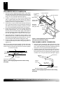
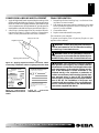
Removing Louver Panels
Remove the top and bottom louver panels by simultaneously pulling
both top end spring latches towards the center of the appliance until
they are disengaged from the locating holes (see Figure 1). Repeat
for bottom spring latches and pull the louvers outward. To install or
replace items removed, simply reverse the procedures above.
Figure 1 - Removing Louver Panel
Louver Panel
Spring Latch
ACCESSING FIREPLACE
The gas control valve and burner orifices are located under the firebox
floor of the appliance and are accessed by removing the lower louver
panel. The pilot orifice is located in the pilot burner and is accessed
by opening the glass door and removing the logs.
Lock
Unlock
Glass
Door
Figure 2 - Opening Glass Door
Latch
Opening Glass Door
1. Remove screen assembly by pushing the rod either left or right
and then down and forward. Set assembly aside.
2. Lift up on latches of door to unlock. There are two on top of
firebox and two below firebox that hold glass door in place (see
Figure 2).
3. Remove log set from firebox. Refer to Installing Logs, Lava
Rock and Glowing Embers in owner’s manual.

111899-01A
For more information, visit www.desatech.com
For more information, visit www.desatech.com
2
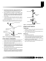
Figure 4 - Removing/Replacing Pan Burner Orifice
(Tube Burner Not Shown for Clarity)
Figure 3 - Removing/Applying RTV Silicone and Locating
Air Shutter
RTV Silicone
Firebox
Bottom
Pan Burner Assembly
TUBE BURNER ORIFICE CONVERSION
1. Inside the control compartment under firebox bottom, locate
aluminum tube with flare fitting and brass elbow on the right
side. Loosen flare fitting and disconnect aluminum tube from
elbow fitting. Use a 3/4" open end wrench (see Figure 5).
2. Carefully cut away RTV silicone from the orifice where it
passes through the firebox bottom (see Figure 5). Remove el-
bow fitting with orifice from burner inlet by turning counter-
clockwise. Use a 7/8" open end wrench (see Figure 6, page 3).
Figure 5 - Removing/Applying RTV Silicone and Locating
Air Shutter
Rear Burner
Firebox
Bottom
RTV Silicone
Rear Burner
Orifice
PAN BURNER ORIFICE CONVERSION
1. Inside the control compartment under firebox, locate alumi-
num tube with flare fitting and adapter fitting on the left side.
Loosen flare fitting and disconnect aluminum tube from adapter
fitting. Use a 3/4" open end wrench (see Figure 3).
2. Carefully cut away the RTV silicone from the adapter fitting
where it passes through the firebox bottom (see Figure 3).
Remove adapter fitting from elbow fitting by turning counter-
clockwise. Use an 11/16" open end wrench.
3. Inside firebox, locate two small burner hold down brackets on
rear of pan burner. Remove screws with phillips screwdriver
and carefully lift pan burner assembly up and out of firebox
(Do not force the assembly during removal.) See Figure 4.
4. Remove elbow fitting with orifice from burner manifold by
turning counterclockwise. Use a 3/4" open end wrench. Re-
move NG orifice from elbow fitting. Apply a light amount of
propane/LP resistant sealant to short threaded end of LP ori-
fice (106, #58) supplied in kit. Thread LP orifice into elbow.
5. Apply light amount of propane/LP resistant sealant to long
threaded end of orifice. Thread elbow fitting with orifice into
burner manifold and tighten by turning clockwise. Use a 3/4"
open end wrench. Make sure elbow fitting faces down.
6. Locate air shutter at end of burner manifold (see Figure 3).
Loosen screw and adjust air shutter to fully open position. Re-
tighten screw.
Note:
Do not replace pan burner assembly in firebox at this time.
Convert the tube burner and pilot assembly first (see Tube Burner
Orifice Conversion, this page, and Pilot Orifice Conversion, page 4).
Air Shutter
Aluminum Tube/Flare Fitting
Air Shutter
Aluminum Tube/Flare Fitting
Front Pan Burner
Front Burner
Orifice
(18mm Hex)
Elbow Fitting
Adapter Fitting
(11/16" Hex)
Aluminum
Tube/Flare
Fitting (3/4" Hex)
Apply
Thread
Sealant
Here Only
Burner
Manifold
Burner Brackets

111899-01A
For more information, visit www.desatech.com
For more information, visit www.desatech.com
3
3
Figure 6 - Removing/Replacing Rear Burner Assembly
Tube Burner
Screw (5/16" Hex)
Tube Burner Orifice
(18mm Hex)
Apply Thread
Sealant Here Only
Elbow (7/8"
Across Flats)
Aluminum Tube/
Flare Fitting
(3/4" Hex)
3. Remove NG orifice from elbow. Apply a light amount of pro-
pane/LP resistant sealant to short threaded end of LP orifice
(104, #59) supplied in kit. Thread LP orifice into elbow.
4. Apply a light amount of propane/LP resistant sealant to long
threaded end of orifice (see Figure 5, page 2). Thread elbow
fitting with orifice into burner inlet and tighten by turning clock-
wise. Use a 7/8" open end wrench. Make sure flare end of el-
bow faces left.
5. Locate air shutter at end of tube burner (see Figure 5, page 2).
Loosen screw and adjust air shutter to full open (maximum)
position. Retighten screw.
Note:
Do not replace tube burner assembly in firebox at this time.
Convert the pilot assembly first (see Pilot Orifice Conversion).
PILOT ORIFICE CONVERSION
1. Remove the pilot hood by pulling up until it disengages from
the barrel. Do not remove the retainer clip (see Figure 7).
2. Remove the pilot orifice from inside the barrel using a 5/32"
allen wrench to unscrew the orifice.
3. Replace pilot orifice with LP orifice supplied with this kit. The
number 30 is stamped on the sleeve for identification. Insert
the small end of the new pilot orifice into the barrel and thread
until tight with the allen wrench.
4. Line up the notch on pilot hood to the positioning tab on the
barrel receiver and snap back into position.
IMPORTANT:
Be careful not to bend or kink the aluminum
tubing during conversion. Make sure the pilot hood and orifice
are properly mated and aligned after finishing this conversion.
Figure 7 - Converting Pilot Orifice
Pilot Hood
Pilot Orifice
Barrel Clip
Pilot Bracket
5/32" Allen
Wrench
REINSTALLING BURNERS
Tube Burner
1. Apply RTV silicone to orifice where it passes through the fire-
box bottom (see Figure 5, page 2).
2. Connect aluminum tube to elbow fitting and tighten flare fit-
ting. Use a 3/4" open end wrench.
Pan Burner
1. Rest pan burner on grate base.
2. Using screws removed in step 3 of Pan Burner Orifice Con-
version, page 2, reattach two small burner hold down brackets
on rear of pan burner to grate base. See Figure 4, page 2.
3. Apply RTV silicone to adapter fitting where it passes through
the firebox bottom (see Figure 3, page 2).
4. Connect aluminum tube to elbow fitting and tighten flare fit-
ting. Use a 3/4" open end wrench.

111899-01A
For more information, visit www.desatech.com
For more information, visit www.desatech.com
4
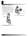
Figure 8 - Removing Mounting Screws, Pressure Regulator
Tower, and Diaphragm/Spring Components
H
I
L
O
O
F
F
P
I
L
O
T
O
N
Mounting Screws
Pressure
Regulator Tower
Diaphragm/Spring
Components
GAS CONTROL VALVE CONVERSION
Convert the gas control valve by swapping out the valve regulator
portion of the gas valve.
1. Using a Torx T20 or slotted screwdriver, remove and discard
the three mounting screws, pressure regulator tower, and dia-
phragm/spring components (see Figure 8).
2. Insure that the rubber gasket is properly positioned on the new
pressure regulator assembly. Install the LP pressure regulator
assembly to the valve using the new mounting screws sup-
plied with the kit. Tighten screws securely (approximately 25
in-lbs.) (see Figure 9).
3. Install the identification label enclosed with the gas valve regula-
tor to the valve body where it can easily be seen (see Figure 9).
H
I
L
O
O
F
F
P
I
L
O
T
O
N
Figure 9 - Installing Pressure Regulator Assembly
Mounting Screws
Rubber
Gasket
Identification Label

111899-01A
For more information, visit www.desatech.com
For more information, visit www.desatech.com
5
5
Figure 10 - Applying English and French Conversion Labels
over Existing Certification Labels on Lighting Instruction Plate
CONVERSION INFORMATION LABEL
This appliance was converted on
(name and address of organization making
this conversion), which accepts the
responsibility that this conversion has been
properly made.
Day Month Year
– – to gas
with Kit No.
by
106080-0156060
Figure 12 - Conversion
Information Label
English This Side
French This Side
Figure 11 - Print Previous
Model Number on Conversion
Labels
Lighting Instruction Plate
CONVERSION LABELING AND PLACEMENT
1. Apply the English and French conversion labels over the top of the
existing certification labels (see Figure 10). Existing certification
labels are located on the lighting instruction plate inside the gas
valve compartment area. With permanent ink, print the previous
model number on the label in the space provided (see Figure 11).
2. After filling in the data required on the conversion informa-
tion label (see Figure 12), affix it to the floor of the appliance
where it is easily seen when the lower louver is removed.
WARNING: Never use an open flame to check for a
leak. Apply noncorrosive leak detection fluid to all joints.
Bubbles forming show a leak. Correct all leaks at once.
WARNING: This conversion kit shall be installed
by a qualified service agency in accordance with the
manufacturer’s instructions and all applicable codes
and requirements of the authority having jurisdic-
tion. If the information in these instruction is not
followed exactly, a fire, explosion, or production of
carbon monoxide may result causing property dam-
age, personal injury, or loss of life. The qualified
service agency is responsible for the proper installa-
tion of this kit. The installation is not proper and
complete until the operation of the converted appli-
ance is checked as specified in the manufacturer’s
instructions supplied with the kit.
FINAL PREPARATION
1. Reinstall logs. Refer to Installing Logs, Lava Rock and Glow-
ing Embers in owner’s manual.
2. Leak check the gas control and any connections you've made
before operating the appliance. Refer to Checking Gas Con-
nections in owner’s manual.
3. Close and latch door.
4. Replace screen and reinstall louver panels.
The conversion is now complete.
To operate your fireplace, refer to Operating Fireplace in your
appliance owner’s manual.
WARNING: Test all gas piping and connections,
internal and external to unit, for leaks after installing
or servicing. Correct leaks at once.
VENTED GAS FIREPLA
VENTED GAS FIREPLA
CE
CE
Conversion Kit Model
Type of Gas
Previous Model #

111899-01A
For more information, visit www.desatech.com
For more information, visit www.desatech.com
6
111899-01
Rev. A
08/03
NOT A UPC
2701 Industrial Drive
Bowling Green, KY 42101
www.desatech.com
111899 01
-
 1
1
-
 2
2
-
 3
3
-
 4
4
-
 5
5
-
 6
6


Desa CHDV36NR-C Owner's manual
- Type
- Owner's manual
- This manual is also suitable for
Ask a question and I''ll find the answer in the document
Finding information in a document is now easier with AI
Related papers
-
Desa Tech PCDE-36VA Owner's manual
-
-
-
-
-
-
Desa 106038-09 User manual
-
FMI MBDV41 User manual
-
 Vexar CD36TN-M User manual
-

Other documents
-
-
-
-
-
-
-
-
FMI CHDV42NR-B Operating instructions
-
-