Danfoss ECL Comfort 300 - C35 Operating instructions

Category
Thermostats
Type
Operating instructions
ECL COMFORT
ECL Comfort
User’s Guide
C35
Contents
Daily use
Section
1 Choose favourite display
2 Select controller mode
3 Adjust room temperature
4 Set personal day plan
5 Advantages of the ECL Card
6 Hot points
7 Definitions
The documentation for the ECL Comfort controller is
composed of numbered sections. Only sections relevant to your
ECL Comfort controller are included here.
Your personal week plan:
Heating 03691215182124
1 Monday
2 Tuesday
3 Wednesday
4 Thursday
5 Friday
6 Saturday
7 Sunday
Hot Water
03691215182124
1 Monday
2 Tuesday
3 Wednesday
4 Thursday
5 Friday
6 Saturday
7 Sunday
The factory setting is indicated in grey.
823-
5 - 8 18 - 22
6-8 16 - 22
Installation and maintenance. Grey sections 10 and
onwards. Turn the guide over.
This guide is associated to ECL Card 087B4759
Installer:
By:
Date:
ECL COMFORT
ECL Comfort
Installation and
Maintenance
Mixing controller with ON/OFF controlled
hot water service
Table of contents
Sections of the Installers part of this guide.
The documentation for the ECL Comfort controller is
composed of numbered sections. Only sections relevant to
your ECL Comfort controller are included here.
Before you start
Installation
10 Identifying the system type
11 Mounting the controller
12 Electrical connections 230 Vac
13 Electrical connections 24 Vac
14 Placing the temperature sensor types
15 Inserting the ECL Card
Basic Set up
16 Adjusting the ECL Card settings
17 Setting the time and date - Line A
18 Monitoring temperatures and system units - Line B
19 Manual control - Line B
20 Setting the heat curve - Line C
21 Heating cut-out - Line 1
22 Flow temperature limits - Line 2
23 Room temperature influence - Line 3
26 Setting PI-regulation - Line 4 - 7
27 Hot water controller - Line 1 and 2
29 Check list
30 ECL Card settings
31 Service parameters
32 Adjusting the service parameterst10 - 199
33 Understanding heating and hot water regulation
34 Copying with the ECL Card
Daily use, turn the guide over sections 01 - 07
1 Choose favourite display
2 Select controller mode
3 Adjust room temperature
4 Set personal day plan
5 Advantages of the ECL Card
6 Hot points
7 Definitions
823-
C35
Control & overviews
Extended Service
Miscellaneous
VI.7C.D3.02
2001.06
The shown diagram is a fundamental and simplified example
and does not contain all components that are necessary in
heating systems.
If the system you are about to install is different than the
shown diagram of a standard heating system, feel free to
sketch an outline for comparison. Adaptation of heating
systems, See section 10.
List of components:
ECL Comfort 300
S1 Outdoor temperature sensor (ESM-10)
S2 Room temperature sensor (ESM-10)
S3 Flow temperature sensor (ESM-)
S4 Return temperature sensor (ESM-)
S6 Hot water temperature sensor (ESM-)
P1 Circulation pump for heating circuit
P2 Charging pump for hot water circuit
M1 Mixing valve with motor
Installation & maintenance
The ECL Card, grey side
for installation and maintenance.
Lines A to C, and lines 1 to
7 for basic settings, see overview
section 30.
Extended service parameters,
see section 31
The ECL Card: Installers
instruction
The grey side of the card must be
turned outward when changing the
settings. For daily use and during
start-up the yellow side of the card
must be turned outward.
Circuit indicator
Circuit
selector
Change of
display
Adjust Controller
mode
The circuit indicator shows the selected heating circuit.
The ECL Card
For daily use and your personal adjustments the yellow side
of the ECL Card must be facing you.
The display
Each line, A, B, C, 1, 2 etc. of the ECL Card has its own
display. See section 1.
Room
temperature /
Hot water
temperature
Heating system
information
Todays
programme
Day plans
A
B
C
1
2
3
4
5
6
7
6
1
2
3
4
Hot water circuit II
6
1
2
3
4
Heating circuit I
Line indicator
Circuit
913
0
A
2
5
1
1
ON
2
ON
036
B
8
0 3 6 9 12 15 18 21 24
1
913
5
C
3
6
0 3 6 9 12 15
0
5
0
8
0 3 6 9 12 15 18 21 24
0
7
0
55
6
A
5
1
1
ON
2
ON
B
8
0 3 6 9 12 15 18 21 24
1
55
5
C
3
6
0 3 6 9 12 15
0
5
0
6
0 3 6 9 12 15 18 21 24
0
7
0
Controller mode
Manual operation (Used only at
maintenance and service)
Automatic operation
Constant comfort temperature
Constant reduced temperature
Standby mode
Arrow buttons. Move between
the lines of the ECL Card.
Shift buttons between temperatures,
changeover points etc.
Adjust temperatures and values etc.
Circuit selector for changing between
heating and hot water circuit.
Controller mode
Manual operation (used only at
maintenance and service)
Automatic operation
Constant comfort temperature
Constant reduced temperature
Standby mode
Arrow buttons. Move between
the lines of the ECL Card.
Shift buttons between temperatures,
changeover points etc.
Adjust temperatures and values etc.
Circuit selector for changing between
heating and hot water circuit.
8
9
10
199
Before you start
Save energy - save money - improve your comfort
temperature
The ECL Comfort controller is designed by Danfoss for
temperature control of heating systems.
The ECL Comfort controller ensures you of the following;
Room and hot water temperatures will be adjusted to
your personal settings.
Lower temperatures and lower energy consumption
reduce costs and ensure optimum use of energy
resources.
The automatic pump motion program protects the
circulation pump against blocking.
Sketch an outline of your heating system.
The ECL Comfort controller is designed for a wide range of
heating systems with different configurations and
capacities.
If your heating system differs from the diagrams shown in
section 10, you may want to sketch an outline of the system
about to be installed. This makes it easier to use the
Installer’s Guide, which will guide you step-by-step
from installation to the final adjustments before the end-
user takes over.
Note! The controller is pre-programmed with factory
settings which are shown in the relevant sections of this
guide.
However, you might come across some settings that
are not listed in this instruction. These settings are used in
connection with optional modules, and you can find a
description of the settings and the corresponding
parameters in the instruction for theoptional module in
question.
How to use this guide
This guide is divided into two parts:
Daily Use (turn the guide over)
Yellow sections 1-7
Installation and maintenance:
Grey sections 10 and onwards
VI.7C.D3.02
2001.06
Installation
Note!
System diagrams in this instruction are principal drawings
and do not contain all components which are necessary in
heating systems.
Identifying the system type
In this section you find the most frequently used systems. If
your system is not quite as shown below, find the diagram
which has the best resemblance to your system and make
your own combinations.
10a
Installation
Alternatives using the same settings:
• Heat exchanger or direct district heating
• 2-, 3-, or 4-way control valve
Alternatives which require different settings:
• Primary or secondary connected hot water circuit
• Charging pump or change-over valve in charging circuit
Heating system type 2
Line 51 Change-over valve/charging pump
Setting
OFF
Line 53 PI reference when heating HW
Setting
OFF
Heating system type 1
Line 51 Change-over valve/charging pump
Setting
ON
Line 53 PI reference when heating HW
Setting
OFF
Heating system type 3
Line 51 Change-over valve/charging pump
Setting
ON
Line 53 PI reference when heating HW
Setting
ON
Heating system type 4
Line 51 Change-over valve/charging pump
Setting
ON
Line 53 PI reference when heating HW
Setting
ON
10b
Installation
Installation
Mounting the ECL Comfort
controller
11a
For easy access, you should mount the ECL Comfort
controller near the heating unit. Select one of the three
following methods:
Mounting on a wall
Mounting on a DIN rail
Mounting in a panel
Screws and rawlplugs are not supplied.
Mounting on a wall
Socket for mounting on wall: Order code No. 087B1149.
Mount the terminal box on a wall with a smooth surface.
Establish the electrical connections and position the
controller in the box. Secure the controller with the fixing
screw.
Mounting on a DIN rail
Mounting kit: Order code No. 087B1145.
A mounting kit is necessary to mount the box with the
controller on a DIN rail.
Mounting in a panel
Connector set: Order code No. 087B1148.
The panel plate thickness must not exceed 3 mm.
Prepare a cut-out with the dimensions 92 x 138 mm. Pull off
the right side of the lid by means of a screwdriver.
Insert the controller into the panel cut-out and fix it with the
two locks which are placed diagonally in two corners of the
controller.
11b
Connecting the temperature sensors
Installation
Establish the jumper from 16 to common terminal
Wire cross section for sensor connections: Min. 0.4 mm
2
Total cable length: Max. 50 m (sensors and bus).
Cable type: Copper cable.
NOTE! Cable lengths above 100 m may cause noise sensibility
(EMC).
12a
Electrical connections -
230 V a.c.
Installation
Wire cross section: 0.75 - 1.5 mm
2
Cable length: Max. 50 m.
Electrical connections
Max. 2 x 1.5 mm
2
wires can be inserted in each screw terminal.
12b
Establish these jumpers:
Jumper from 1 to 5, 5 to 10, 10 to 12
and 2 to common N-terminal
1 L Voltage supply 230 V a.c.
2 N Voltage supply 230 V a.c.
3 M1 Gear motor - open max 0.2 A / 230 V a.c.
4 M1 Gear motor - close
alt.: ABV thermo
actuator max 0.2 A / 230 V a.c.
5 Phase for M1
9 P1 Circulation pump for
heating circuit max 4(2) A / 230 V a.c.
10 Phase for pump relay
11 P2 Charging pump/
change-over valve max 4(2) A/230 V a.c.
12 Phase for pump relay
Establish these jumpers:
Jumper from 1 to 10, 10 to 12
and 2 to common N-terminal
This circuit diagram is only valid if Danfoss actuators are used
Terminal Description Type (recommended)
15 and 16 System device bus
17 and 16 Outdoor sensor (S1) ESM-10
18 and 16 Room sensor (S2) ESM-10
19 and 16 Flow sensor (S3) ESMU/ESM-11/
ESMC
20 and 16 Return sensor (S4) ESMU/ESM-11/
ESMC
22 and 16 Hot-water sensor (S6) ESMU/ESMB
230 V a.c. connections - without safety thermostat
230 V .a.c. connections - with safety thermostat
Terminal Description Max. load
Connecting the temperature sensors24 V a.c. connections - without safety thermostat
13a
Electrical connections -
24 V a.c.
Establish the jumper from 16 to common terminal
Wire cross section for sensor connections: Min. 0.4 mm
2
Total cable length: Max. 50 m (sensors and bus).
Cable type: Copper cable.
NOTE! Cable lengths above 100 m may cause noise sensibility
(EMC).
Establish these jumpers:
Jumper from 1 to 5, 5 to 10, 10 to 12
and 2 to common N-terminal
Wire cross section: 0.75 - 1.5 mm
2
Cable length: Max. 50 m.
Electrical connections
Max. 2 x 1.5 mm
2
wires can be inserted in each screw terminal.
* K1/K2 auxiliary relay coil 24 V a.c.
13b
15 and 16 System device bus
17 and 16 Outdoor sensor (S1) ESM-10
18 and 16 Room sensor (S2) ESM-10
19 and 16 Flow sensor (S3) ESMU/ESM-11/
ESMC
20 and 16 Return sensor (S4) ESMU/ESM-11/
ESMC
22 and 16 Hot-water sensor (S6) ESMU/ESMB
24 V a.c. connections - with safety thermostat
This circuit diagram is only valid if Danfoss actuators are used
Terminal Description Max. load
1 L Voltage supply 24 V a.c.
2 N Voltage supply 24 V a.c.
3 M1 Gear motor - open 1 A / 24 V a.c.
4 M1 Gear motor - close
alt.: ABV thermo actuator 1 A / 24 V a.c.
5 Phase for M1
9 K1* Relay for circulation pump
for heating circuit I 4(2) A / 230 V a.c.
10 24 V a.c. supply for
pump relay R1
11 K2 Relay for charging pump
/change-over valve for hot-
water service circuit I 4(2) A / 230 V a.c.
12 24 V a.c. supply for
pump relay R2
Terminal Description Type (recomm.)
Establish these jumpers:
Jumper from 1 to 10, 10 to 12
and 2 to common N-terminal
Installation
Placing the temperature
sensors
Installation
It is important that the sensors are mounted in the correct
position in your heating system.
Special attention should be paid to the following sensors:
Outdoor temperature sensor
(ESM-10 type)
The outdoor sensor should be mounted on the north side
of the building where it is less likely to be exposed to
direct sunshine. It should not be placed close to doors or
windows.
Flow temperature sensor
(ESMU, ESM-11 or ESMC types)
Place the sensor max. 15 cm from the mixing point. In
systems with heat exchanger, Danfoss recommends the
ESMU-type to be inserted into the exchanger flow outlet.
Make sure that the surface of the pipe is clean at the area
where the sensor is mounted.
Return temperature sensor
(ESMU, ESM-11 or ESMC types)
The return sensor should always be placed max. 15 cm
from the mixing point. It should always be placed on a pipe
in which the water flow never stops.
Room temperature sensor
(ESM-10, ECA 60 and 61 remote control)
Place the room sensor in the room where the temperature
is to be controlled. Do not place it on outside walls or close
to radiators, windows or doors.
Hot water temperature sensor
(ESMU or ESMB types)
Place the hot water sensor according to the
manufacturers specification.
14
Note!
Valid for ESM-11: Do not move the sensor after it has been
fastened in order to avoid damage to the sensor element.
Installation
15a
Inserting the ECL Card
The controller is now ready to be set to control your
heating system.
Installation
How to insert your ECL Card the first time
After the power has been switched on, open the lid on the
front side of the controller.
Place the ECL Card with the yellow side facing you. This
enables the controller to read the ECL Card data. The
controller immediately starts to copy the factory settings
and heating system type from the ECL Card. After copying,
the display will show the heating system type the controller
is set to control. After approx. 10 seconds the display will
change to display line C.
Desired room
temperature
CYp
0
O9C
C53
05 108
8
0 3 6 9 12 15 18 21 24
1
913
5
C
3
Understanding the ECL Card
The ECL Card contains factory settings for a standard
heating system. If the actual heating system differs from
the standard system, the controller must be adjusted
accordingly. After the adjustment, the new settings should
be stored on the ECL Card.
For ECL Card copying and daily use including
adjustment of temperatures and time periods, insert the
ECL Card with the yellow side facing you.
For system set-up adjustments, the grey side of the ECL
Card - the installers side - must be facing you.
As a main rule, the ECL Card should always remain in
the controller during service, maintenance and settings.
If the card is removed please note that:
The controller settings are locked after approx. 10 min.
The ECL Card must not be exposed to direct heat or
sunshine
If several controllers are installed in the heating system
you can write a title on the ECL Card with a permanent
ink pen.
ECL Card
version
Controller
version
Line
Circuit
Time
Outdoor
temperature
15b
0
1
1
ON
2
ON
094
2
17
Setting the time and date -
Line A
Basic set-up
In case of a power failure which lasts longer than 12 hours,
the time and the date have to be set again.
All other settings are stored as programmed.
Go to line A.
Use the shift button to switch between minutes,
hours, year, month and day.
Set the correct time and date.
Use the yellow side of the ECL Card to enter the day
plan settings.
See Users Guide, section 4.
16
Adjusting the ECL Card
settings
General principles
When the controller is connected and operating you can
check and adjust all or some of the basic settings on the
grey side of the ECL Card.
When the copying is finished display line C will appear.
Basic set-up
CYp
0
O9C
8
0 3 6 9 12 15 18 21 24
1
913
5
C
3
Update of the ECL Card after maintenance and service
All new settings can be stored on the ECL Card. For details
about copying, see section 34. Insert the ECL Card with the
yellow side facing you.
You can make other changes in the day plan, set time and
date or change settings
(see Users Guide).
Use the arrow buttons to move from line to
line of the ECL Card, for example line 2:
Settings to
be adjusted
Value in
range indicator
Line
indicator
Circuit
Use the minus / plus buttons to adjust the
settings.
In some displays more than one setting or value
can be adjusted. Use the shift button to switch
between the possibilities.
The circuit selector shifts between circuit I and II.
You can adjust all settings and service
parameters individually in both circuits.
Go to line 9 (bottom line).
Accept to copy as indicated. No other keys are
active.
01
01
63110
5
A
3
Actual time
Month, day
Year
The grey
side of the
ECL Card
19
Go to line B
Manual control - Line B
Basic set-up
Shift to manual mode
Monitoring temperatures
and system units - Line B
18
Basic set-up
The activity of the motorized valve is shown as arrows
below the valve symbol. When the circulation pump is
operating, it is indicated as ON below the pump
symbol.
If a sensor is not mounted or is disconnected, the display
will indicate it as - -”.
If the sensor is short-circuited, the display will indicate it as
- - - “.
If you are in doubt, remove the controller and check the
ohmic value between the relevant terminals.
Go to line B
5
1
1
ON
2
ON
036
B
Controlled units
State indicator
Return temperature
Flow
temperature
Push the shift button to see:
- the calculated flow temperature
- the return temperature set points.
5
1
2
ON
036
B
1
ON
Controlled
units
Controller
mode
Relationship between temperature and ohmic value
-50
800
900
1000
1100
1200
1300
1400
1500
1600
-25 0 25 50 75 100 125 150
Ohm
The grey
side of the
ECL Card
The grey
side of the
ECL Card
The gear motor
opens or closes
the valve as long as the the relevant button is
pressed.
The thermo actuator
(according to version *)),
opens (NO) or closes (NC)
the valve as long as the relevant button is
pressed.
*) NO - normally open
NC - normally closed
Pumps are switched off or on when the
relevant button is pressed.
Note!
During manual operation, the pump motion is OFF.
1
ON
1
Check the activation direction of the motorized valve either
by looking at it or by feeling whether the temperature of the
actual pipe changes as expected.
This operation applies to both circuits. Press the
button to select circuit II.
Select the unit you want to control. The selected
unit symbol will flash.
1
1
Temperature
-10 °C 961 Ohm
0 °C 1000 Ohm
10 °C 1039 Ohm
20 °C 1078 Ohm
30 °C 1117 Ohm
40 °C 1156 Ohm
50 °C 1195 Ohm
60 °C 1234 Ohm
70 °C 1273 Ohm
80
o
C 1312 Ohm
90
o
C 1351 Ohm
100
o
C 1390 Ohm
110
o
C 1429 Ohm
1
1
Basic set-up
-20 -10 0 10 20-30
20
30
40
50
60
70
80
90
1.0
1.4
0.6
0.2
1.8 2.2 3.0 3.4
100
110
2.6
o
C
o
C
Setting the heat curve -
Line C
20a
Basic set-up
Adjust the slope of the heat curve, if required.
Make your adjustments.
8
C
1
1
2
ONON
2
ON
3
ON
0
Go to line C.
The symbol for the slope of the heat curve will
flash.
Slope
Displacement
8
C
1
1
2
ONON
2
ON
3
ON
0
If you want to adjust the parallel displacement of
the heat curve, push the shift button. The
symbol for the parallel displacement will flash.
20b
Slope
Circuit Setting range Factory setting
I 0.2 ... 3.4 1.8
Parallel displacement
Circuit Setting range Factory setting
I -9... +9 0
Floor heating systems
This controller is factory set for radiator systems which
typically are high flow temperature systems.
To control floor heating systems, which typically is low flow
temperature systems, you need to change the heat curve
according to your type of system.
Parallel displacement
Circuit Setting range Typical setting
I -9... +9 0
Slope
Circuit Setting range Typical setting
I 0.2 ... 3.4 1.0
The grey
side of the
ECL Card
The grey
side of the
ECL Card
Flow temperature limits -
Line 2
22
Basic set-up
Go to line 2.
The left end of the range indicator flashes.
Adjust the min. limit to your heating system.
Select the max. limit. The right end of the range
indicator flashes.
Adjust the max. limit.
Heating cut-out - Line 1
21
Basic set-up
1
2
ON
8
1
1
1
ON
Go to line 1
Set the outdoor temperature limit at which you
want the heating system to stop.
This function can save energy by stopping the heating
system when the outdoor temperature gets above a set limit.
The heating system is activated again when the actual
outdoor and the accumulated temperatures get below the set
limit.
The accumulated T
out
symbolises the heat stored in the
building.
18 ˚C
Temperature
Actual T
out
Accumulated T
out
Time
Heating Heating off Heating
0
1
1
ON
2
ON
094
2
Max. flow
temperature
Min. flow
temp.
Temperature
range for flow
temperature
1 Limit for heating cut-out
Circuit Setting range Factory setting
I 10 ... 30 °C 18 °C
2 Flow temperature min., max. limits
Circuit Setting range Factory setting
I 10 ... 110 °C min. 40 °C max. 90 °C
The grey
side of the
ECL Card
The grey
side of the
ECL Card
ON
OFF
+
_
+
_
Basic set-up
Room temperature
influence - Line 3
23a
Basic set-up
The room sensor in the reference room registers
the difference between the desired and the
actual room temperature. The flow temperature
reference will be corrected to eliminate this
difference.
B: Reference room control
Used if your heating system is not equipped with radiator
thermostats and you select the room with room sensor as a
temperature reference for the rest of the rooms.
(However, should you have a few radiator thermostats
installed, make sure that they are fully open).
Set a positive value for min. influence and a
negative value for max. influence.
This section is only relevant if you have installed a room
sensor or ECA 60/61. There are two basic principles for
control of the room temperature influence:
A: Max. room temperature limitation
Use this limitation if your heating system is fully equipped
with radiator thermostats and you also want to obtain a
max. limitation of the room temperature. The controller will
allow for free heat gains, i.e. solar radiation or heat from a
fire place, etc.
The max. influence determines how much the
room temperature should influence the flow
temperature.
Go to line 3.
Select the max. influence.
The bar below the range indicator flashes in the
right side of the display.
Adjust the max. influence.
Example
The actual room temperature is 2 degrees too high.
The influence at max. limitation (right corner of the display) is
set to -40.
The influence at min. limitation (left corner of the display) is
set to 0.
Heat curve H is 1.8.
Result:
The flow temperature reference is changed by
2 x -40 x 0.1 x H = -14.4 degrees.
Example 1:
The actual room temperature is 2 degrees too low.
The influence at max. limitation (right corner of the display) is
set to -20.
The influence at min. limitation(left corner of the display) is set
to 20.
Heat curve H is 1.8.
Result:
The flow temperature reference is changed by
2 x 20 x 0.1 x H = 7.2 degrees.
Example 2:
The actual room temperature is 2 degrees too high.
The influence at max. limitation (right corner of the display) is
set to -35.
The influence at min. limitation(left corner of the display) is set
to 35.
Heat curve H is 1.8.
Result:
The flow temperature reference is changed by
2 x (-35) x 0.1 x H = -12.6 degrees.
1
2
ON
0-40
3
1
ON
Min.
influence
Max.
influence
Influence
T
ROOM
Set
T
ROOM
Max. limitation
Set T
ROOM
Influence
Min. limitation
Max. limitation
T
ROOM
23b
3 Room temperature influence
Circuit Setting range Factory setting
I 0 ... 99 / -99 ... 0 min. 0 max. -40
The grey
side of the
ECL Card
The grey
side of the
ECL Card
Basic set-up
Setting the PI-regulation
Line 4-7
26a
Basic set-up
Go to line 4.
Set the proportional band.
A higher value will result in a stable, but slow
regulation of the flow temperature.
Go to line 5.
Set a high integration time constant to obtain a
slow but stable reaction to deviations.
A small integration constant will make the
controller react fast but with less stability.
Go to line 6.
Set the running time of the motorized valve
according to the example on the opposite page.
This is the time it takes the valve to move from
closed to fully open position.
1
2
ON
4
80
1
ON
Setting to be adjusted
Line
indicator
Go to line 7.
Set the neutral zone to a high value if you can
accept a high variation in flow temperature.
When the actual flow temperature is within the
neutral zone, the controller does not activate the
motorized valve.
26b
4 Proportional band
Circuit Setting range Factory setting
I 1 ... 250 K 80 K
5 Integration time constant
Circuit Setting range Factory setting
I 5 ... 999 sec. 30 sec.
6 Running time of the motorized valve
Circuit Setting range Factory setting
I 5 ... 250 sec. 35 sec.
7 Neutral zone
Circuit Setting range Factory setting
I 0 ... 9 K 3 K
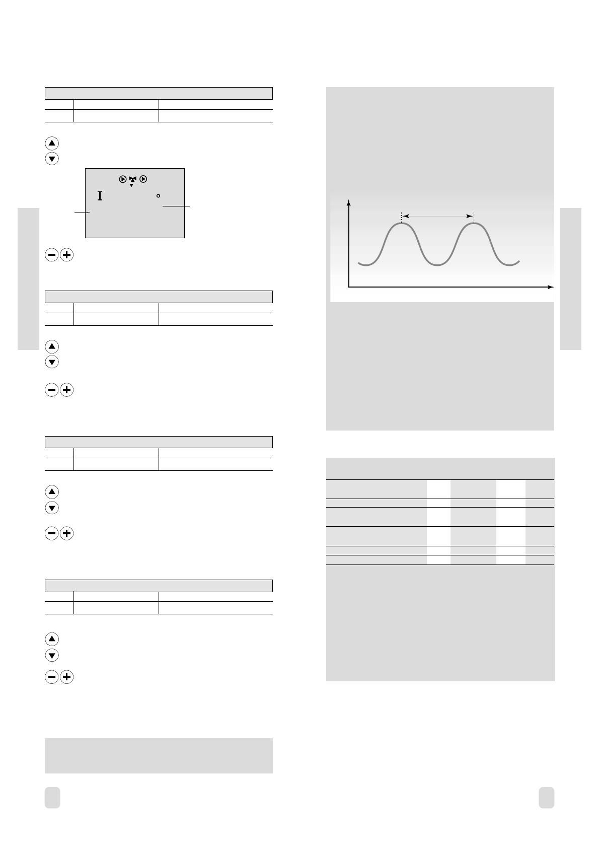
If you want to tune the PI-regulation precisely, you can
use the following method:
Set the integration time (line 5) to its max. value (999 sec.).
Decrease the value for the proportional band (Line 4) until
the system starts hunting with a constant amplitude (it might
be necessary to force the system by setting an extreme
value).
Find the critical time period on the temperature recording or
use a stop watch.
This time period will be characteristic for the system, and you
can evaluate the settings from this critical period.
Integration time = 0.85 x critical time period
Proportional band = 2.2 x proportional band value in the
critical time period.
If the regulation seems to be too slow, you can decrease the
proportional band value by 10%.
Note! Make sure there is a consumption when you set the
parameters.
How to calculate the running time of the motorized valve
The running time of the motorized valve is calculated using the
following methods:
Seated Valves
Running time = Valve stroke (mm) x actuator speed (sec /
mm)
Example: 5.0 mm x 15 sec / mm = 75 sec.
Rotating Valves
Running time = Turning degrees x actuator speed (sec / degr.)
Example: 90 degrees x 2 = 180 sec.
Valve type Valve Actuator Actuator Running
stroke type speed time
(mm) (sec./mm) (sec.)
VS2 15 3.0 AMV 100 90 250
VS2 15...25, VM2 15...25, AMV(E)
VB2 15...20 5.0 10, 20 15 75
VS2 15...25, VM2 15...25,
VB2 15...20 5.0 AMV(E) 30 3 15
VM2 32, VB2 25 7.0 AMV(E) 20 15 105
VM2 32, VB2 25 7.0 AMV(E) 30 3 21
The grey
side of the
ECL Card
The grey
side of the
ECL Card
Time
Temperature
Critical time period
Note!
The neutral zone is symmetrical around the flow reference
value.
Go to line 2.
The difference between cut-in temperature and cut-out
temperature during hot water charging.
Basic set-up
1
1
ON
2
ON
6
2
Set the hot water temperature difference.
Hot water controller -
Line 1 and 2
27a
Here you can set the difference between charging
temperature and desired hot water temperature.
Basic set-up
Example:
Desired hot water temperature 60 °C
Charging temperature difference 15 K
Charging temperature
(60+15 =) 75 °C
Go to line 1.
1
1
ON
2
ON
5
1
1
Line
Circuit
Set the difference. Set a high value if you want
the hot water system to reach the desired
temperature in a short period of time.
Note!
A too high charging temperature might cause deposits in the
heat exchanger.
27b
1 Charging temperature difference
Circuit Setting range Factory setting
II 1 ... 30 K 15 K
2 Hot water temperature difference
Circuit Setting range Factory setting
II 1 ... 30 K 6 K
The grey
side of the
ECL Card
The grey
side of the
ECL Card
Charging temperature difference
Hot water difference
Charging temperature
Desired hot water temperature
Adapting the ECL Comfort controller to the heating
system
29b
Check list
Turn the ECL Card so that the grey side faces
you.
Set the time and the date (Line A).
See section 17.
Check all settings on the grey side of the
ECL Card.
See sections 20 to 27.
Please check all settings in the extended
service parametres line 10 to 199.
Control & overviews
29a
Check list
Is the ECL Comfort controller ready for use?
Make sure that the power supply is connected to
terminals 1 (Live) and 2 (Neutral).
See section 12.
Check that valves and pumps are connected to
the correct terminals.
See section 12.
Check that all sensors are connected to the
correct terminals.
Mount the controller, and switch on the power.
Insert the ECL Card with the yellow side facing
you and push
, if necessary.
See section 15.
Select manual operation in the controller mode.
See section 2
in the Users Guide.
Check that valves open and close, and that
pumps start and stop when operated manually.
See section 19.
Check that the temperatures shown in display A
and B match the actual sensors, both for
circuit I (heating) and circuit II (hot water).
See section 1
in the Users Guide.
Control & overviews
Control & overviews
ECL Card settings
(circuit II: Hot water service)
30b
1
Charging temperature
1 ... 30 K 15 K
Set the temperature the system needs in
order to be able to reach the desired hot
water temperature, see section 27.
2
Hot water temperature difference
1 ... 30 K 6 K
Set the difference between the cut-in and
cut-out limits of the hot water temperature,
see section 27.
Control & overviews
ECL Card settings
(circuit I: Heating)
30a
A Time and date See sections 16 & 17
B System informationSee sections 18 & 19
C Heat curve See section 20
A Time and date See sections 16 & 17
B System informationSee sections 18 & 19
Heat curve - Slope
0.2 ... 3.4 1.8
Set the slope of the heat curve, see section
20
Heat curve - Parallel displacement
-9 ... +9 0 K
Set the parallel displacement of the heat
curve, see section 20
1
Limit for heating cut-out
10 ... 30 °C 18 °C
Save energy by stopping the heating
system when the outdoor temperature gets
above a certain limit, see section 21.
2
Flow temperature min.- / max. limits
10 ... 110 °C min. 40, max. 90 °C
The limits for min. - and max. flow
temperature, see section 22.
3
Room temperature influence
0 ... 99 / -99 ... 0 min. 0, max. -40
The room temperatures influence on the
flow temperature control, see section 23.
4
Proportional band
1 ... 250 K 80 K
Set the PI-regulation, see section 26.
5
Integration time constant
5 ... 999 sec. 30 sec.
Set the PI-regulation, see section 26.
6
Running time of the motorized valve
5 ... 250 sec. 35 sec.
Set the PI-regulation, see section 26.
7
Neutral zone
0 ... 9 K 3 K
Set the PI-regulation, see section 26.
Setting range Factory setting Your settings Setting range Factory setting Your settings
Control & overviews
Service parameters
31b
Service parameters
31a
Control & overviews
Circuit II (hot water service)
Line Setting range Factory setting Your setting
51 Change-over valve / charging pump
ON / OFF OFF
52 Closed valve / normal operation
ON / OFF OFF
53 Reference temperature at S3 when
charging hot water
ON / OFF OFF
141 Override input selection
OFF / 1 ... 6 OFF
Circuit I (heating)
Line Setting range Factory setting Your setting
10 Choice of room panel / remote
control
0 ... 5 0
11 Reduced temperature dependent
on outdoor temperature
OFF / -29 ... +10 °C -15 °C °C
12 Boost
0 ... 99% 0% %
14 Optimising time constant
OFF / 10 ... 59 OFF
15 Adaptive function of room
temperature
OFF / 1 ... 30 OFF
17 Temperature reference feedback
OFF / 1 ... 20 OFF K
20 Optimisation based on room /
outdoor temperature
ON / OFF OFF
21 Total stop
ON / OFF OFF
22 Pump motion
ON / OFF ON
23 Valve motion
ON / OFF OFF
24 Gear motor / thermo actuator
ON / OFF ON
30 Limitation of return temperature
10 ... 110 °C 50 °C °C
35 Return temperature influence
- max.
-9.9 ... 0 ... +9.9 °C -2 °C °C
36 Return temperature influence
- min.
-9.9 ... 0 ... +9.9 °C0 °C °C
37 Adaptive function of return
limitation
OFF / 1 ... 50 25
141 Override input selection
OFF / 1 ... 6 OFF
174 Motor protection
OFF / 10...59 min OFF
196 Service pin LON
ON / OFF OFF
197 LON reset
ON / OFF ON
198 Summer time change
ON / OFF ON
199 Slave address
0 ... 9 15
-29 to +10 °C
The setting of reduced temperature depends on
the outdoor temperature, when the outdoor
temperature is above the set limit.
The lower the outdoor temperature the less the
temperature reduction. When the outdoor
temperature is below the set limit, there is no
temperature reduction.
OFF: The reduced temperature setting will be
constant at all outdoor temperatures.
100%
0%
-20 -10-29 0 10 2015
Reduction
Outdoor temperature
o
C
32b
Service parameters 10-11
Note!
The time control of the hot water circuit is always dedicated
to the day plan of circuit II.
Extended service
32a
Adjusting the service
parameters
Extended service
In addition to the settings in line 1 to 7 on the grey side of
the ECL Card, there is an extended service menu from line
10 and onwards.
When you have entered all your personal settings, turn the
ECL Card over so that the yellow side faces you.
If you want to copy the new settings to the ECL Card
(recommended by Danfoss), see section 34.
Make a note of your new settings on the parameter list in
section 31.
Push repeatedly to reach the lines
numbered 10 and onwards.
Line
number
Value
Range indicator
01
0
Now you can move to any line of your choice.
Set the parameter value.
You can select any of the two circuits no matter
what line you are in. You will not necessarily
enter the same line number.
See the service parameters in section 31.
10 Choice of room panel / remote control
Circuit Setting range Factory setting
I 0 ... 5 0
Decides the communication with the room panel or remote
control. Choose either 1 or 2 if you have installed a room panel
or remote control.
11 Reduced temperature dependent on outdoor
temperature
Circuit Setting range Factory setting
I
OFF / -29 ... +10 °C -15 °C
The outdoor temperature at which the reduced temperature
setting is switched off. Below this outdoor temperature, the
reduced temperature setting has no influence.
The grey
side of the
ECL Card
Choose between
0 ECL Comfort controller - week plan
circuit I.
1 Room panel ECA 60 or remote control
ECA 61 on address A.
2 Room panel ECA 60 or remote control
ECA 61 on address B.
3 ... 5 Not used
  • Page 1 1
  • Page 2 2
  • Page 3 3
  • Page 4 4
  • Page 5 5
  • Page 6 6
  • Page 7 7
  • Page 8 8
  • Page 9 9
  • Page 10 10
  • Page 11 11
  • Page 12 12
  • Page 13 13
  • Page 14 14
  • Page 15 15
  • Page 16 16
  • Page 17 17
  • Page 18 18
  • Page 19 19
  • Page 20 20
  • Page 21 21
  • Page 22 22
  • Page 23 23
  • Page 24 24
  • Page 25 25
  • Page 26 26
  • Page 27 27
  • Page 28 28
  • Page 29 29
  • Page 30 30
  • Page 31 31
  • Page 32 32
  • Page 33 33

Danfoss ECL Comfort 300 - C35 Operating instructions

Category
Thermostats
Type
Operating instructions

Ask a question and I''ll find the answer in the document

Finding information in a document is now easier with AI