Page is loading ...

English
www.mundoclima.com
Installation manual
CASSETTE TYPE INDOOR UNIT
CL23810 to CL23819
MVH-H-Q4CDN1
MVH-H-Q4DN1
'HIDEN' SERIES MVH

CONTENTS
Installation and owner's manual ..............................................................
3
Installation and owner's manual
Thank you for selectiong super quality Air Conditiones. To ensure satisfactory operation for many ears to come,
this manual should be read carefully before the installation and before using the air conditioner. After reading,
store it a safe place. Please refer to the manual for questions on use or in the event that any irregularities occur.
This Air Conditioner should be used for hosehold use.
This unit must be installed by a professional according RD 795/2010, RD 1027/2007 and RD 238/2013.
The power supply must be SINGLE-PHASE (one phase (L) and one neutral (N)) with his grounded power (GND))
switch. Any breach of these specifications involve a breach of the warranty conditions provided by the manufacturer.
In line with the company's policy of continual product improvement, the aesthetic and dimensional characteristics,
technical data and accessories of this appliance may be changed without notice.
IM
PORTANT
WARNING
NOTE
Read this manual carefully before installind or operating you new air conditioning unit. Make sure to save this
manual for future reference.
ATTENTION
or THREE-PHASE (three phase (L1, L2, L3) and one neutral (N) with his grounded power (GND)) and his manual
Remote controller manual ......................................................................
27
2
MUNDOCLIMA HIDEN Series
MVH Cassette

1 ……………………………………………………Safety precautionary measures
2 ……………………………………………………… Selection of Installation Site
3 ………………………………………………………… Installation of indoor unit
4 Drain pipe layout …………………………………………………………………
5 Install connecting pipes and electronic throttle ……………………………………
6 Connection of Electricity …………………………………………………………
7 ……………………………………………………… Supplying and controlling
8 Fault code table …………………………………………………………………
INSTALLATION AND OWNER'S MANUAL
Contents
……………………………………………………………
9 Indoor unit information
5
6
7
15
17
20
22
25
26
3
MUNDOCLIMA HIDEN Series
MVH Cassette

Heat insulation
1
10
6
3
Drain pipeDrain pipe
1
2
1
4
4
1
2
Used to hang the air conditioner
Used to fasten drainpipe
Used to drain water
Accessories and parts purchased locally
Numbers
Shape
The manual
Application
(Please be sure to hand it to user.)
To encase single joints of high
and low pressure pipes.
1
2
Accessories
Bind up cables and connecting pipes.
RibbonRibbon
Dome insulated tipDome insulated tip
X-type insulated tipX-type insulated tip
Used to connect wires
Used to connect wires
Remote controller Remote controller
BatteryBattery
Supply power to remote controller
Control A/C
Connecting pipe of
electronic expansion
valve
Connecting pipe of
electronic expansion
valve
Connect electronic expansion valve and liquid side of
indoor unit (Different models may have different sizes and
calibers. Please install according to the real products.)
4
Blank valve bagBlank valve bag
Used to contain accessories.
Used to hang the air conditioner
Large-sized heat
insulating mattress
Large-sized heat
insulating mattress
Parts Purchased Locally
Type
Liquid pipe
(mm)
Gas pipe
(mm)
For the indoor unit drainpipe. The length is decided according to the actual need.
Assort inner diameter respectively with relevant copper pipe and hard polyethylene plastic
pipe. The thickness is usually 10 mm (above). It should be appropriately thickened in
closed and wet areas.
2.2kW~2.8kW 3.2kW~5.6kW
7.1kW~8.0kW 9.0kW~16.0kW
Φ 9.52 × 0.8
φ 12.7 × 0.8
φ 9.52 × 0.8
φ 15.88 × 1.0
Φ 6.35 × 0.8
4
MUNDOCLIMA HIDEN Series
MVH Cassette

NoticeNotice
!
1. Safety Precautionary Measures
WarningWarning
!
lThe installation work must be done by the installer or a professional worker.
The installation worker must be equipped with all related knowledge as a wrong operation may
cause fire risk, electric shock, injury or water leakage, etc.
lParts purchased locally should be according the nationnal regulations, the violation of which
may cause fire, electric shock or water leakage, etc. The installation work of retailed
products must be installed by professionals.
lIf the unit has to be installed in a small room, suitable measures shall be done to make sure any
refrigerant leakage concentration if happened in the room will not exceed the critical level.
lFor detailed measures, place consult with the distributor.
lConnection of power supply must be complying with rules speci ied by the local electrical
authority.
lRequired by law, must be reliable ground works. If the ground is not perfect, it may result in
electric shock.
lIf the air conditioner need to be moved or reinstalled, please let the installer or a professional
worker operate.
lIncorrect installation will cause fire risk, electric shock, injury or water leakage, etc.
lThe user is not permitted to rebuild or repair the unit by themselves.
Incorrect repairing will cause fire risk, electric shock, injury or water leakage, etc, so repairing
must be performed by the installer or a professional worker.
f
5
MUNDOCLIMA HIDEN Series
MVH Cassette

2-2 Space Needed for Installation
As to space needed for installation of ceiling-style indoor unit, please refer to the following figure.
Space needed for installation Unit mm :( )
2. Selection of Installation Site
2-1 Selection of Installation Site for Indoor Unit
1 ) Provide enough space for installation and maintenance.
2 ) The ceiling is horizontal and the building construction can support indoor unit.
3 ) Ventilation is accessible and the site suffers from the minimal impact of extraneous air.
4 ) Air stream can spread to everywhere of the room.
5 ) Connecting pipe and drainpipe are easy to be extracted.
6 ) No direct radiation of heat.
7 ) ℃If the temperature and humidity of the ceiling exceeds respectively 30 and RH80%, please
stick insulating material on the body of the air conditioner. Please use glass wool or expanded
polyethylene etc., which is more than 10 mm thick. (If it is more than 10 mm, please collect it in the
opening of the ceiling.)
H
2500 above the ground
Above 1000
Exhaust
port
Exhaust
port
Air return
port
Above 1500
Above 1500
Above 1500
Above 1500
Notes: Actual sizes are subject to real products.
Model
5.6kW~8.0kW
2.2kW~4.5kW
9.0kW~16.0kW
Size(H)
232
267
286
6
MUNDOCLIMA HIDEN Series
MVH Cassette

3-1 Preparation before Installation
3. Installation of Indoor Unit
警告
WarningWarning
!
3-1-1 For the position relation between ceiling opening and unit as well as hanging screw bolt,
please refer to the following figure
Hanger bracket
Ceiling
Above 20
Instruction:
1)The overlap section of the ceiling and decorative panels should be over 20 mm. If necessary,
strike out openings needed for installation on the ceiling (for existent ceiling).
2)As for the size of the opening on the ceiling, please refer to installation drawing.
3)Before installation, accomplish all pipes (refrigerator pipe, drain pipe) and wires (indoor and
outdoor unit cables) connected with the indoor unit, so that they can be connected immediately with
the indoor unit after installation.
4)Strike out openings which are possibly needed to reinforce the ceiling frame on the ceiling so
as to ensure a level ceiling and prevent the ceiling from vibrating. For details, please consult
builders.
the ceiling.
3-1-2 Installation of hanging screw rod
To support the unit, if there is a ceiling, use sill anchors; if it is a new ceiling, use buried
anchors, embedded anchors or other parts provided on the spot. Before continuing the
installation, adjust the distance between it and
( ) :mmIn
stallation Examples Unit
Anchors
Long nut or screw thread device
Roof
50~10
0
Hanging screw bolt
Ceiling
7
MUNDOCLIMA HIDEN Series
MVH Cassette

3-2 Installation of Indoor Unit
3. Installation of Indoor Unit
No installation position on the ceiling
①Attach the hanger bracket on hanging screw bolts. Be sure to respectively use nuts and washers
on both ends of the hanger bracket so as to ensure that the hanger bracket is fixed firmly.
Strongback 7 may prevent the washer from dropping.
②For the size of the opening on the ceiling, please refer to the following Installation Board 5. For
details, please consult builders or carpenters.
③Adjust the unit to a correct installation position.
④Check if the unit is horizontal or not.
Indoor unit is furnished with built-in draining and floating switch. Check if the 4 angles of the unit
are level with leveling instrument or water-filled polyethylene pipe .(If the opposite direction of water
condensation leans, floating switch may not work, which will cause dripping.)
⑤Remove Strongback 7 which is used to prevent waterproof washer from dropping and screw the
nuts on it.
⑥Remove installation boards.
B.With installation position on the ceiling
①Temporarily install indoor unit and attach the hanger bracket on hanging screw bolt. Be sure
to respectively use nuts and washers on both ends of the hanger bracket so that the hanger
bracket is fixed firmly. Strongback 7 may prevent the washer from dropping.
②Adjust the height and position of the unit.
③Carry out procedures ④ and ⑤ of “A. No installation position on the ceiling”.
Wa
sher 3 (accessory)
Hanger bracket
Screw (double nuts)
[Fix hanger bracket firmly]
Leveling instrument
Polyethylene pipe
Insert
Washer Strongback 7 (accessory)
[ ]Fix washer firmly
One angle of the exit of pipe is the angle of
sink fixed by nuts.
The center of the
opening on the ceiling
Installation Mould 5
Screw 6 (accessory)
[ ]Fixe installation mould
Nut (provided on the spot)
8
MUNDOCLIMA HIDEN Series
MVH Cassette

3-3 Installation of Panels
Before installing decorative panels, please prepare in accordance with the following figures.
3-3-1 Preparation of Decorative Panels
3-3-2 Install Decorative Panels on Indoor Unit
Diagram for Installation Orders of Ceiling-styled Panels
3. Installation of Indoor Unit
Arrangement of decorative panels
1)Don't turn decorative panels upside down. Don't lean against the wall or protuberant articles.
2)Avoid collision and squeezing of swing panels. (Otherwise it will cause fault.)
Take down the wind grill from decorative panels.
1)Press down the button of wind grill, and then lift one end of the button. (Refer to Figure 1 )
2)Lift up the grill to about 45° and take off the wind grill on decorative panels. (Refer to Figure 2)
Take down the close cover of the angle.Extract the cover outward. (Refer to Figure 3)
Figure 1
Figure 2
Figure 3
1) As shown in the figure, direct the electric motor of swing panel of decorative panels at the pipe
of indoor to install the decorative panels on indoor unit.
2)Installation of decorative panels.
As for the installation orders of decorative panels, please refer to the following installation
diagrams of decorative panels described in details.
9
MUNDOCLIMA HIDEN Series
MVH Cassette

Diagram of Clearance between Ceiling-Style Panel and Real Indoor Unit
3. Installation of Indoor Unit
1)Temporarily install decorative panels on indoor unit. When installing, hang the hanging buckle of
electric motor of swing panel of decorative panels on opposite position over the hanger of indoor
unit. (Attention! Don't involve wire of the electric motor of swing panel into sealing material.)
2)Temporarily hang the remaining two hanging buckles over the hangers of indoor unit. (Attention:
Don't involve wire of the electric motor of swing panel into sealing material.)
3)Screw 4 hexagon bolts under the hanging buckle in about 5 mm. (Panel will lift.)
4)As shown in the figure, turn decorative panels to the direction of the arrows for adjustment so as
to totally cover the opening on the ceiling.
5)Screw bolts so that the thickness of packing material between decorative panels and indoor unit
can be reduced to 5 mm to 8 mm as shown in the following figure.
NoticeNotice
!
The cassette unit panels should be correctly installed and level. Otherwise it will cause a
series of problems. See the following diagram:
If the bolts are not screwed properly,
it will cause the faults as shown in the
following figure. Screw the bolts again
to meet the requirements.
After screwing the bolts, if there is still
gap between the ceiling and decorative
panel, please readjust the height of indoor
unit. There should be no gap.
If indoor unit is level and drain-pipe
does not drain, it will be fine to adjust
the height of indoor unit through the
holes of decorative panels.
10
MUNDOCLIMA HIDEN Series
MVH Cassette

3-4 Hanging height of indoor unit
3-4-1 After the installation of indoor unit, please adjust hanging height of indoor unit. See the
following figure.
Diagram of Hanging height of the cassette unit
3-4-2 If there is gap between indoor unit and panel, the following unfavorable conditions may
occur.
3. Installation of Indoor Unit
11
MUNDOCLIMA HIDEN Series
MVH Cassette

3-5 Wire Connection of Indoor Unit Body and Panel
3-6 Installation of Wind Grill and Cover
3 5 1 Connect wire joints of electric motor of swing panel. (on decorative panels)
3 5 2 If joints are not connected, swing panel will not work. Be sure to properly connect joints.
3 5 3 Check if wire of electric motor of swing panel is placed between indoor unit and decorative
panel.
- -
- -
- -
Diagram for Wire Connection of Indoor Unit Body and Panel
3. Installation of Indoor Unit
Correctly insert four bolts on
the cover into corresponding
holes of the panel before
installation.
(1) Installation of wind grill
Install according to reverse procedures
of “Preparation of Decorative Panel”.
Turn around the wind grill and install in
four directions. If it is necessary to adjust
the installation direction of wind grill, or
users propose such requirement,
change its installation direction.
( )2 Fix the cover on the angle
As shown in the following figure, connect
the string of cover with the bolt of the
decorative panel.
When installing the wind grill, be sure
not to involve wire of electric motor of
swing panel.
Install the cover on the
decorative panel .(refer
to the following figure)
Correctly insert four bolts on the
cover into corresponding holes of
the panel before installation.
12
MUNDOCLIMA HIDEN Series
MVH Cassette

3. Installation of Indoor Unit
3-7 Installing Size of Indoor Unit
A 、 Cassette Unit(1):Appearance Size and Air Outlet Size of
GG
HH
2.2kW~4.5kW
653
A B C D E F G H I
585 267 528 528 212 650 650 30
Size code
Model of
indoor unit
Body size
Installing size
Panel size
U
n
it
: mm
Electronic expansion valve box
CC
FF
II
AA
DD
BB
EE
13
MUNDOCLIMA HIDEN Series
MVH Cassette

B 、 Cassette Unit(2):Appearance Size and Air Outlet Size of
GG
HH
BB
DD
AA
EE
CC
FF
JJ
Electronic expansion valve box
5.6kW~8.0kW
900
900
A B C D E F G H I
833
833
232
286
776
776
684
684
91
150
950
950
950
950
80
80
9.0kW~16.0kW
Size code
Model of
indoor unit
Body size
Installing size
Panel size
Unit: mm
14
MUNDOCLIMA HIDEN Series
MVH Cassette

4. Drain Pipe Layout
4-1 Installation of Drainpipe of Indoor Unit
1)PVC pipe (external diameter 30~32 mm, inner diameter 25 mm) can be used as drainpipe.
Users can purchase drainpipe of appropriate length from distributor, local air conditioning service
center or market according to actual installation.
2)Encase the mouth of drainpipe into the root of pumping pipe of main part and fasten together
the drainpipe and insulating bushing with hoops (accessory).
3)Evenly bind up the pumping connecting pipe and drainpipe (especially indoor part) with
insulation bushing, and tighten them with tightening belt to avoid air inflow and condensation.
4)In order to prevent water from flowing back into air conditioner when it stops, drainpipe should
decline outside(water drain side) the room with an angle of 1/100 or above. Avoid expansion, water
storage, etc., or abnormal noise will occur(see figure4.1a).
5)When connecting drainpipe, don't pull it hard, in case the pumping connecting pipe gets loose
and comes off. Set a supporting point in every 0.8 to 1.0 m, in case that drainpipe may flex. (See
Figure 4.1b)
6)If it is necessary to arrange winding pipe, please use the connecting pipe part of water exit in
electrical connector.
7)When connecting lengthened drainpipe, wrap the indoor part of it so as to prevent lengthened
drainpipe from getting loose.
8)If the exit of drainpipe is higher than pumping connecting pipe of main body, drainpipe should
be kept vertical upwards as it is possible. The connecting pipe part of water exit has the function of
bending vertically and the drainpipe should be set within 600 mm from water tray. Otherwise, when it
stops, too much water that flows back will cause overflow. (See Figure 4.2)
9)Set 1-2 exhaust pipe on the highest position of drainpipe so as to avoid the occurrence of gas
sealing in drainpipe which may cause poor drainpipe.
10)The distance between the end of drainpipe and the bottom of sink must be more than 50 mm,
and don't put drainpipe into water. When directly pouring condensed water into drainage ditch, use
upward bent drainpipe into a U-shape water seal to prevent bad smell from entering room through
drainpipe.
NoticeNotice
!
Don't exert too much strength to avoid destruction of pumping pipe; insulating bushing
of pumping pipe and drainpipe should be encased evenly in order to prevent water
condensation.
NoticeNotice
!
Seal all connections of drainpipe system so as to prevent leakage.
Figure 4.1
0.8~1.0m
a
>1.0m
b
Inclination is above 1/100
15
MUNDOCLIMA HIDEN Series
MVH Cassette

Water test hole
Main body
Water tray
Water test cover
Injection pipe
Exhaust plug
Figure 4.3
4-2-1 Drainage test is needed for new room before paving the ceiling.
4-2 Drainage Test
6
5
6
Fault (if any) should be removed immediately.
50
~
100mm
50
~
100mm
50
~
100mm
200mm以下
Gr
adient is above 1/100
Fi
gure 4.2 Drainpipes of Several Unites Connect with Sewer through Main Drainpipe
Air exhaust
pipe 1
4. Drain Pipe Layout
Below 200 mm
Below 200 mm
Air exhaust
pipe 2
Connecting pipe parts of water exit
Main connecting pipe parts of water exit
All below 600 mm
1)
.
Remove water trying cover, through water trying mouth; inject about 2,000 ml of water into water
tray through injection pipe (See Figure 4.3)
2)Turn on the power. Operate the air condition in cooling mode. Check the operation noise of
draining pump and check if the outfall can drain normally (in accordance with the different length of
drainpipes, it may need about 1 minutes to drain ) and if the interfaces leak.
Pumping connecting pipe
NoticeNotice
!
NoticeNotice
!
Drain plug under the bottom of main body is used for draining water in water tray when air
condition is in fault and maintenance. During using, plug well this drain plug in case of leakage.
3)Stop the air conditioner. Check if there are any abnormal conditions after 3 minutes. If
drainpipe is arranged unreasonably, too much water will flow back, which will cause alarming of
control box, flashing of indicator and even overfall of water tray.
4)Continue to add water and it will alarm due to high water level. Check if draining pump drains
water immediately. If water level can't drop down under warning level after 3 minutes, the unit will
stop. At this time, turn off the power and drain water before turning it on normally.
5)Turn off the power, drain water and install the water testing cover back to the original place.
16
MUNDOCLIMA HIDEN Series
MVH Cassette

5.Install Connecting Pipes and Electronic Throttle
5-1 Requirements for the connecting length and drop height of the tubing of both
indoor and outdoor units
)1 Please refer to the allowed length of tubing in the instruction of outdoor unit.
2)Please refer to the allowed drop height of tubing in the instruction of outdoor unit.
5-2 Material and Size of Tubing
5-3 Procedures for Connecting Pipes
NoticeNotice
!
During the installation process, keep the air, dust and other impurities from getting into the pipeline
system.
Fix indoor and outdoor units before installing the connecting pipe.
Keep dry while installing the connecting pipe and keep the water from getting into the pipeline system.
Connecting pipe must be wrapped by heat insulator. (Usually, the thickness is more than 10 mm, and it
is even thicker in closed humid area.)
5-3-1 Measure the needed length of connecting tubing, and make connecting tubing according to the
flowing methods. (For details, see the “Tubing Connection” column)
Connect the indoor unit before connecting the outdoor unit.
a.Pay attention to the configuration of winding tubing so as not to damage the tubing and its
insulation layer.
b.Smear the refrigerator oil (it must be engine oil which is compatible with the cooling medium of this
type) on the outside surface of flared joint and the conical surface of connecting nut and screw it 3 or 4
rounds with your hand (Fig. 5.1) before screwing the flared nut up.
c.Use two spanners at the same time when connecting or taking the tubing down.
d.The interface of indoor unit can't bear all the weight of the connecting tubing, because if the
interface is over-burdened, it will affect the cooling or heating effects of indoor unit.
2)The stop valve of outdoor unit should be completely shut down (as the default state when leaving the
factory). Unscrew the nut from the stop valve and connect the flared tube at once (within 5 minutes).
3)After connecting the refrigerant tubing to both indoor and outdoor units, eliminate the air according to
the column of “ ”, then screw the nut up.
a.Notes for flexible coupling:
①The winding angle should be less than 90°(Fig. 5.2).
②Its sinuosity had better be in the centre of the pipe range, its bending radius should be more than
3.5 D (the diameter of pipeline).
③Don't bend the flexible coupling pipe for more than 3 times.
Vacuum Supply
Smear refrigeration oil
Figure 5.1
Bend pipe with thumbs
Figure 5.2
Table 5.1
TypeType
Liquid pipes
(mm)
Liquid pipes
(mm)
Gas pipes
(mm)
Gas pipes
(mm)
3.2kW~5.6kW2.2kW~2.8kW 7.1kW~8.0kW 9.0kW~16.0kW
φ 6.35 × 0.8
φ 9.52 × 0.8
φ 12.7 × 0.8φ 9.52 × 0.8
φ 15.88 × 1.0
17
MUNDOCLIMA HIDEN Series
MVH Cassette

5-4 Connection of Pipe
5-4-1 Flaring
1) .Cut off pipe with a pipe cutting knife (See Figure 5.4)
2) .Insert the pipe into the connected flared nut (Table 5.2)
5-4-2 Fasten Nuts
Aim at the connecting pipe and screw up nuts with hand and then screw them up with wrenches as
shown in Figure 5.5.
90
5-3-2 Pipe Arrangement
Table: 5.3
pipes size
(mm)
Tightening torque
( N.m)
Tightening torque
N.m ( )
φ 6.35
φ 9.52
φ 12.7
φ 15.88
φ 19.05
10 ~ 12
15 ~ 18
20 ~ 23
28 ~ 32
35 ~ 40
b. .
①
Bending thin-wall connecting pipe (Fig. 5.3)
Cut away a notch of a required size in the insulated tubing at the place of
sinuosity when operating with the sinuosity, then expose the pipeline (wrap it up
with binder after it gets bent).
②Bend radius as much as possible so as to avoid squash or destruction.
③Use pipe bender to make close sinuosity.
c.Use copper pipe sold in the market:
When using the copper pipe purchased in the market, you must use the same
type insulating material (thickness is often more than 10 mm, and it is even
thicker in closed humid area.).
Remove coil methods
make pipe end straight
Figure 5.4
1)It is necessary to bend pipe or drill holes on the wall. The section surface of bending pipe should not
exceed 1/3 of original section surface. When drilling wall or board, ensure to set protection bushings.
Welding lines are not allowed to be made within the protection bushings. When drilling external wall for the
pipe, ensure to seal it tightly with binder so as to prevent impurities from entering the pipe. The pipe should
be insulated by appropriate and suitable insulating tube.
2)The encased connecting pipe should get through the hole on the wall from outside and enter into the
room. Arrange pipes carefully. Don't destroy pipes.
Inclination
Crassitude
Burr
Table 5.2
φ6.35
φ9.52
φ12.7
φ15.88
φ19.05
(mm)(mm)
A(mm)
8.7
12.4
15.8
19.0
23.3
8.3
12.0
15.4
18.6
22.9
R0.4~0.8
45
°
±
2
90
°
±
4
A
Maximum
Minimum
NoticeNotice
!
In accordance with installation conditions, too large torque will break loudspeaker while too small
torque will cause leakage of air. Please ensure that the torque has been screwed up according to
Table 5.3.
Figure 5.5
Figure 5.3
5.Install Connecting Pipes and Electronic Throttle
18
MUNDOCLIMA HIDEN Series
MVH Cassette

5-5-2 Maintenance diagram of electronic throttle parts
Figure 5.6
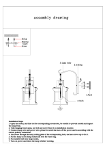
5-5-1 Schematic Diagram for Installation of Electronic Throttle Component
5-5 Installation of Electronic Throttle Component and Connecting Pipe Assembly
Electronic throttle parts have been installed on unit body when leaving the factory. Please refer
to Figure 5.6. When installing the entire unit, please joint connecting nuts of electronic throttle parts
with liquid pipe of evaporator and screw it up with torque wrench.
Electronic throttle parts have been installed on unit body when
leaving the factory. They are connected by four nuts. Refer to
Figure 5.6. Please carry out maintenance of electronic throttle
parts in accordance with the following steps:
1)Collect as much refrigerant air back to outdoor unit as
possible.
2)Open maintenance opening.
3)Open electronic throttle parts, connecting pipe and
connecting nuts of the unit.
4)Remove set screws of electronic throttle parts and the unit
with cross screwdriver.
5)Remove the whole electronic throttle parts from the
machine, unscrew fixed screws and remove the cover.
6)Check and repair electronic throttle parts, etc.
Connecting pipe
of electronic
expansion valve
Gas pipe of indoor unit
Liquid pipe of
indoor unit
Set screws
Electronic expansion
valve box
This side connects
with liquid pipe of
outdoor unit.
Never use refrigerant sealed in outdoor unit to vacuumize.
5-8 Valve Switch
Use 5 mm hex socket to open and close the valve of outdoor unit.
5-9 Leak Detection
When detecting leakage, detect leak in the valves at the interface of the pipe joints with soap
bubbles.
5-10 Insulated Treatment
5-6 Leakage Test
After having installed refrigerant pipe, connect it before outdoor unit. Inject nitrogen with certain
pressure (4.0MPa) from gas pipe side and liquid pipe side at the same time to take leakage test for
24 hours.
Connect refrigerant pipe with the two sides of gas pipe and liquid pipe of outdoor, use vacuum
pump to vacuumize from the two sides of gas pipe and liquid pipe of outdoor at the same time.
NoticeNotice
!
5.Install Connecting Pipes and Electronic Throttle
Insulate gas pipe side and liquid pipe side. When refrigerating,
the temperature of gas pipe side and liquid pipe side should be
low. To prevent condensation, please fully insulate (See Figure
5.7).
1) Gas pipe must be made from insulated material which can
resist more than 120℃.
2) Please seamlessly insulate the connecting parts of indoor unit
single joints with accessorial .insulating tube
Incision to upword
Main body
On-the-spot
pipe side
Figure 5.7
Rubber and plastic
heat preservation pipe
A insulating tubeccessorial
5-7 Vacuum Supply
19
MUNDOCLIMA HIDEN Series
MVH Cassette

6. Connection of Electricity
Warning
!
As you review this manual, along with the wiring instructions presented in this section, keep in mind that:
all field-installed wiring must conform to National Electric Code (NEC) guidelines, and any applicable state
and local codes. Be sure to satisfy proper equipment grounding requirements per NEC.
!
6-1 Electric Wiring
6-2 Specification of Power Supply
The specification of power supply wires recommends the following Figure 6.1. Wirings may be overheated
and the machine will break down if the capacity is too small.
Table 6.1
NoticeNotice
!
Air conditioning applies special power supply and power supply voltage should conform to the rated
voltage.
The external power supply circuit of air conditioning must have ground wire. Power supply’s ground
wire of indoor unit should be connected accurately with external circuit.
Wiring should be installed by professional technicians according to labeling of circuit diagram.
The connected fixed circuit must be furnished with an all-pole disconnection equipment with at least
3mm trigger distance.
Install protective equipment of creepage in accordance with standard of national electrical equipment
technology.
Power and signal lines should be appropriately arranged in good order, and can not interfere with
each other.
Meanwhile, they cannot connect with connecting pipes and valve body. At the same time, two wires
cannot be connected, unless they are welded firmly and wrapped with insulating tapes.
After installation has done, before connecting to power supply, please check carefully and make sure
everything is fine.
6-3 Wiring Suggestion of Signal Wire of Indoor Unit
1)Shielded wire should be used as signal wire. Using other wires may cause signal interference and
malfunction.
2)Wiring shielding layers of shielded wire into one line and then connect it to port E of terminal. (See
Figure 6.1)
3)It is forbidden to tie the signal wire with refrigerant pipe, power supply wires etc. When power supply
wires are paved in parallel with signal wire, they should keep a distance of more than 300mm to avoid
interference of signal source.
4)Signal wire cannot form a closed circuit.
5)Signal wire contains polarity, so be careful when connecting wires.Signal wire of indoor unit should
be connected to ports labeled “P, Q, E”. And they should conform to ports labeled “P, Q, E” of the main
machine of outdoor unit and cannot be connected wrongly.
Power supply of indoor part
Power supply
Power
switch
Capacity
Fuse
Power Cord
Below 20 m
Connecting wire
Signal wire of indoor
and outdoor units
Number
Wire diameter
Ground
wire
1
2.2~16.0kW
Below 50 m
Single-phase
15A 15A
2.5mm²×2
4 ×2mm²
Single wire
2.5mm²
3-core
shielded cable
0.75mm²
20
MUNDOCLIMA HIDEN Series
MVH Cassette
/