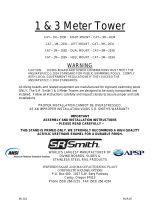
S.R.Smith SlideAway is designed and manufactured for installation and use on inground swimming pools only. With a maximum user weight of 125 lb (57 kg) and a sitting slide position, facing forward, feet first, the S.R.Smith SlideAway is intended for recreational use in private residential swimming pools; either in-ground or above-ground pools. The SlideAway slide must be placed on the pool in a location that meets the requirements of the manufacturer’s placement instructions. The SlideAway support brace must be installed when the slide is in use.
S.R.Smith SlideAway is designed and manufactured for installation and use on inground swimming pools only. With a maximum user weight of 125 lb (57 kg) and a sitting slide position, facing forward, feet first, the S.R.Smith SlideAway is intended for recreational use in private residential swimming pools; either in-ground or above-ground pools. The SlideAway slide must be placed on the pool in a location that meets the requirements of the manufacturer’s placement instructions. The SlideAway support brace must be installed when the slide is in use.


-
 1
1
-
 2
2
-
 3
3
-
 4
4
-
 5
5
-
 6
6
-
 7
7
-
 8
8
-
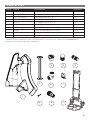 9
9
-
 10
10
-
 11
11
-
 12
12
-
 13
13
-
 14
14
-
 15
15
-
 16
16


S.R.Smith SlideAway is designed and manufactured for installation and use on inground swimming pools only. With a maximum user weight of 125 lb (57 kg) and a sitting slide position, facing forward, feet first, the S.R.Smith SlideAway is intended for recreational use in private residential swimming pools; either in-ground or above-ground pools. The SlideAway slide must be placed on the pool in a location that meets the requirements of the manufacturer’s placement instructions. The SlideAway support brace must be installed when the slide is in use.
Ask a question and I''ll find the answer in the document
Finding information in a document is now easier with AI
Related papers
-
 S.R.Smith SlideAway™The Safe Removable Pool Slide Owner's manual
-
 S.R.Smith T7™ Diving System Installation guide
-
 S.R.Smith Cyclone Pool Slide Installation guide
-
 S.R.Smith Typhoon® Pool Slide Installation guide
-
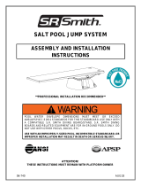 S.R.Smith Salt Pool Jump System Installation guide
-
 S.R.Smith Cantilever Jump Stand Installation guide
-
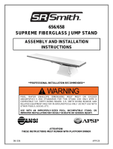 S.R.Smith Supreme Jump Stand Installation guide
-
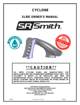 S.R.Smith Cyclone Pool Slide Owner's manual
-
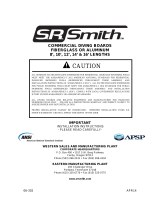 S.R.Smith Frontier III Commercial Board Installation guide
-
 S.R.Smith Deluxe™ (1 Meter) Tower Installation guide


Other documents
-
 Little Giant Ladders 15270-001 User guide
-
Blue Wave NE122SS Installation guide
-
-
Helix S.R. SMITH Assembly And Installation Instructions Manual
-
-
ADEMCO 5820 Installation And Setup Manual
-
Kensington 1900791 Datasheet
-
Blue Wave NE9877 User manual
-
 The Vinyl Works NE120T Operating instructions
-
S R Smith 400-7001 Owner's manual

