Page is loading ...

To understand this product, and for safety and
optimum performance, read this manual before
starting the engine. Pay special attention to
SAFETY INSTRUCTIONS highlighted by this
symbol.
It means CAUTION, WARNING or DANGER—
personal safety instruction. Failure to comply with
the instruction may result in personal injury.
OPERATOR’S
MANUAL
FORM NO. 3321-307 Rev A
MODEL NO. 03540-80001 & UP
MODEL NO. 03541-
80001 & UP
MODEL NO. 03543-
80001 & UP
MODEL NO. 03544-
80001 & UP
REELMASTER
®
5200-D/5400-D
®
©The TORO COMPANY—1998

2
Table of Contents
This operator's manual has instructions on safety, operation, and maintenance.
This manual emphasizes safety, mechanical and general product information. DANGER, WARNING and
CAUTION identify safety messages. Whenever the triangular safety alert symbol appears, understand the
safety message that follows. “IMPORTANT” highlights special mechanical information and “NOTE”
emphasizes general product information worthy of special attention.
IDENTIFICATION AND ORDERING
MODEL AND SERIAL NUMBER
The model and serial number for the traction unit is on a plate that is mounted on the left front frame member.
The model and serial number for the cutting unit is on a plate that is mounted on the top front of the center
cutting unit. Use model and serial number in all correspondence and when ordering parts.
To order replacement parts from an authorized TORO Distributor, supply the following information:
1. Model and serial numbers of the machine.
2. Part number, description and quantity of parts desired.
NOTE: Do not order by reference number if a parts catalog is being used; use the part number.
Page
Safety 3
Specifications 9
Before Operating 10
Controls 13
First-Time Operation 16
Operating 20
Maintenance 22

3
Safety
Training
1. Read the instructions carefully. Be familiar with
the controls and the proper use of the equipment.
2. Never allow children or people unfamiliar with
these instructions to use the lawn mower. Local
regulations may restrict the age of the operator.
3. Never mow while people, especially children, or
pets are nearby.
4. Keep in mind that the operator or user is
responsible for accidents or hazards occurring to
other people or their property.
5. Do not carry passengers.
6. All drivers should seek and obtain professional
and practical instruction. Such instruction should
emphasize:
• the need for care and concentration when
working with ride-on machines;
• control of a ride-on machine sliding on a
slope will not be regained by the application
of the brake. The main reasons for loss of
control are:
– insufficient wheel grip;
– being driven too fast;
– inadequate braking;
– the type of machine is unsuitable for
its task;
– lack of awareness of the effects of
ground conditions, especially slopes;
– incorrect hitching and load distribution.
Preparation
1. While mowing, always wear substantial footwear
and long trousers. Do not operate the equipment
when barefoot or wearing open sandals.
2. Thoroughly inspect the area where the
equipment is to be used and remove all objects
which may be thrown by the machine.
3. WARNING—Petrol is highly flammable.
• Store fuel in containers specifically
designed for this purpose.
• Refuel outdoors only and do not smoke
while refueling.
• Add fuel before starting the engine. Never
remove the cap of the fuel tank or add
petrol while the engine is running or when
the engine is hot.
• If petrol is spilled, do not attempt to start
the engine but move the machine away from
the are of spillage and avoid creating any
source of ignition until petrol vapors have
dissipated.
• Replace all fuel tanks and container caps
securely.
4. Replace faulty silencers.
Operation
1. Do not operate the engine in a confined space
where dangerous carbon monoxide fumes can
collect.
2. Mow only in daylight or in good artificial light.
3. Before attempting to start the engine, disengage
all blade attachment clutches and shift into
neutral.
4. Do not use on slopes of more than:
• Never mow side hills over 5°
• Never mow uphill over 10°
• Never mow downhill over 15°
5. Remember there is no such thing as a “safe”
slope. Travel on grass slopes requires particular
care. To guard against overturning:
• do not stop or start suddenly when going up
or downhill;
• engage the clutch slowly, and always keep
the machine in gear, especially when
travailing downhill;

Safety
4
• machine speeds should be kept low on
slopes and during tight turns;
• stay alert for bumps and hollows and other
hidden hazards;
• never mow across the face of the slope,
unless the lawn mower is designed for this
purpose.
6. Use care when pulling loads or using heavy
equipment.
• Use only approved drawbar hitch points.
• Limit loads to those you can safely
control.
• Do not turn sharply. Use care when
reversing.
• Use counterweight(s) or wheel weights
when suggested in the instruction
handbook.
7. Watch out for traffic when crossing or near
roadways.
8. Stop the blades rotating before crossing
surfaces other than grass.
9. When using any attachments, never direct
discharge of material toward bystanders nor
allow anyone near the machine while in
operation .
10. Never operate the lawn mower with defective
guards, shields or without safety protective
devices in place.
11. Do not change the engine governor settings or
overspeed the engine. Operating the engine at
excessive speeds may increase the hazard of
personal injury.
12. Before leaving the operator’s position:
• disengage the power take-off and lower the
attachments;
• change into neutral and set the parking
brake;
• stop the engine and remove the key.
13. Disengage the drive to attachments when
transporting or not in use.
14. Stop the engine and disengage the drive to the
attachment
• before refueling;
• before removing the grass catcher;
• before making height adjustments unless
the adjustment can be made from the
operator’s position.
• before clearing blockages;
• before checking, cleaning or working on
the lawnmower;
• after striking a foreign object. Inspect the
lawnmower for damage and make repairs
before restarting and operating the
equipment.
15. Reduce the throttle setting during engine run-
out and, if the engine is provided with a shutoff
valve, turn the fuel off at the conclusion of
mowing.
Maintenance and Storage
1. Keep all nuts, bolts and screws tight to be sure
the equipment is in safe working condition.
2. Never store the equipment with petrol in the
tank inside a building where fumes may reach
an open flame or spark.
3. Allow the engine to cool before storing in any
enclosure.
4. To reduce the fire hazard, keep the engine,
silencer, battery compartment and petrol
storage area free of grass, leaves, or excessive
grease.
5. Check the grass catcher frequently for wear or
deterioration.
6. Replace worn or damaged parts for safety.
7. If the fuel tank has to be drained, this should
be done outdoors.

5
Safety
8. Be careful during adjustment of the machine to
prevent entrapment of the fingers between
moving blades and fixed parts of the machine.
9. On multi-bladed machines, take care as rotating
one blade can cause other blades to rotate.
10. When the machine is to be parked, stored or
left unattended, lower the cutting means unless
a positive mechanical lock is used.
Sound & Vibration Levels
Sound Levels
This unit has a continuous A-weighted sound
pressure level of 88 dB(A), based on measurements
of identical machines per Directive 91/386/EEC and
amendments.
This unit has a sound power level of 101 LWA,
based on measurements of identical machines per
Directive 84/538/EEC and amendments
Vibration Levels
This unit has a vibration level of 1.3 m/s
2
at the
hands, based on measurements of identical machines
per ISO 5349 procedures.
This unit does not exceed a vibration level of 0.5
m/s
2
at the posterior, based on measurements of
identical machines per ISO 2631 procedures.

6
Symbol Glossary
Caustic liquids,
chemical burns to
fingers or hand
Poisonous
fumes or toxic
gases, asphyxiation
Electrical shock,
electrocution
High pressure
fluid, injection
into body
High pressure
spray, erosion of
flesh
High pressure
spray, erosion of
flesh
Crushing of
fingers
or hand,
force
applied from
above
Crushing of
toes or foot, force
applied from above
Crushing of
whole body,
applied from
above
Crushing of
torso, force
applied from side
Crushing of fingers
or hand/, force
applied from side
Crushing of
whole body
Crushing of
head, torso and
arms
Cutting of
fingers or hand
Cutting of footCrushing of leg,
force applied
from side
Cutting or
entanglement of
foot, rotating auger
Severing of
foot, rotating
knives
Severing of
fingers or hand,
impeller blade
Wait until all
machine
components have
completely stopped
before touching them
Severing of
fingers or hand,
engine fan
Whole body entanglement,
implement input drive line
Fingers or
hand entangle-
ment, chain drive
Runover/back-
over, (relevant
machine to appear
in dashed box)
Machine tipping,
riding mower
Machine rollover,
ROPS (relevant
machine to appear
in dashed box)
Stored energy
hazard, kickback
or upward motion
Hot surfaces,
burns to fingers
or hands
Hand & arm
entanglement,
belt drive
Thrown or fly-
ing objects, whole
body exposure
Thrown or
flying objects,
face exposure
Explosion Fire or open
flame
Secure lifting
cylinder with locking
device before getting
in hazardous area
Stay a safe
distance from
the machine
Stay clear of
articulation area
while engine is
running
Do not open
or remove safety
shields while
engine is
running
Do not step on
loading platform if
PTO is connected to tractor
& engine is running
Do not step
Shut off engine
& remove key before
performing mainten-
ance or repair work
Riding on this
machine is allowed
only on a passen-
ger seat & only if the
driver’s view is not
hindered
Consult
technical manual
for proper service
procedures
Fasten seat belts Safety alert
triangle
outline safety
alert symbol
Read operator’s
manual

7
Safety
Fire, open light
& smoking
prohibited
Hydraulic
system
Brake system
Oil Coolant (water) Intake air Exhaust gas Pressure
Level
indicator
Liquid level Filter Temperature Failure/
Malfunction
Start switch/
mechanism
On/start Off/stop
Plus/increase/
positive polarity
Engage Disengage
Attachment
lower
Attachment
raise
Spacing distance Snow thrower,
collector auger
Minus/decrease/
negative polarity
Horn Battery charging
condition
Hourmeter/elapsed
operating hours
Fast Slow Continuous
variable, linear
Volume empty Volume full
Machine travel
direction,
forward/rearward
Control lever
operating
direction, dual
direction
Control lever
operating
direction, multiple
direction
Clockwise
rotation
Counter-clock-
wise rotation
Grease
lubrication
point
Oil lubrication
point
Lift point
Jack or
support point
Draining/
emptying
Engine lubricat-
ing oil
Engine lubricating
oil pressure
Engine lubricating
oil level
Engine lubricating
oil filter
Engine
lubricating oil
temperature
Engine coolant
Flush with water Engine Transmission
Hearing
protection must
be worn
Caution, toxic
risk
Eye protection
must be worn
Head protection
must be worn
First aid

8
Transmission
failure/malfunction
Clutch Neutral High Low Forward Reverse Park
NHLFRP
First gear Second gear
Third gear (other #'s
may be used until
the maximum # of for-
ward gears is reached.)
Hydraulic oil Hydraulic oil
temperature
231
Hydraulic oil
pressure
Hydraulic oil level Hydraulic oil filter
Hydraulic oil
failure/malfunction
Parking brake Fuel Fuel level Fuel filter Fuel system
failure/malfunction
Diesel fuel Unleaded fuel
Headlights Lock Unlock Differential lock 4-Wheel drive Power Take-Off Power Take-Off,
rotational speed
Reel cutting
element
Reel cutting
element, height
adjustment
Traction Above working
temperature range
Drilling Manual metal arc
welding
Manual 0356 Water pump
0626 Keep dry
0430 weight Do not dispose
in the garbage
CE logo
Engine coolant
pressure
Engine coolant f
ilter
Engine
lubricating oil
pressure
Engine intake/
combustion air
Engine intake/
combustion air
pressure
Engine intake/
air filter
Engine start Engine stop
Engine failure/
malfunction
Engine rotational
speed/frequency
Choke Primer (start aid) Electrical preheat
(low temperature
start aid)
Transmission oil Transmission oil
pressure
n/min
Transmission oil
temperature
Safety

Engine: Kubota three-cylinder, 4-cycle, liquid-
cooled diesel. 18.6 kW (25 hp) @ governed to 3200
rpm; 1123 cc displacement. Heavy-duty, 3-stage,
remote-mounted air cleaner. High water temperature
shutdown switch.
Cooling System: Radiator capacity is 7.1 l (7.5 qt.)
of 50/50 mixture of ethylene glycol anti-freeze.
Remote mounted .9 l (1 qt.) expansion tank. A two-
speed fan drive controls air flow.
Fuel System: Fuel tank capacity is 37.9 l (10 gal.)
of #2 diesel fuel. Equipped with a fuel filter/water
separator to capture water in the fuel.
Traction System: Foot pedal controls forward/
reverse ground speed. Ground speed: 0–16.1 kmh
(0–10 m.p.h.) forward and 0–6.4 kmh (0-4 mph)
reverse. Hydrostatic transmission mounted directly
on a 20.9:1 ratio front axle. Axle/reservoir capacity
is 4.7 l (5 qts). Replaceable filter mounted directly
on transmission housing. Model 03541—
Mechanical rear axle is coupled to the front axle by
a drive shaft and overrunning clutch.
Cutting Unit Drive System: Hydraulic reel motors
feature quick disconnects to ease
removal/installation on cutting units. Hydraulic
fluid reservoir capacity is 32.2 l (8.5 gal.). System
protected by a filter assembly with service indicator.
Seat: Deluxe high back seat with adjustable fore
and aft travel, weight and height. Tool box at the left
side of the seat.
Steering System: Power steering with dedicated
power source.
Tires: Two rear tires: 19 x 8.50-8, tubeless, 4-ply
rating. Two front tires: 26 x 12.00-12 tubeless, 4-
ply rating. Recommended tire pressure for the front
and rear tires is 69–103 kPa (10–15 psi).
Brakes: Individual drum-type wheel brakes on the
front traction wheels. Brakes controlled by
individual pedals operated by the left foot.
Hydrostatic braking through traction drive.
Electrical System: Automotive type electrical
system. 12-volt, maintenance free battery with 530
cold cranking Amps @ –18°C (0° F) and 85 minute
reserve capacity @ 29° C (85° F). 40-amp alternator
with regulator/rectifier. Seat switch, reel and
traction interlock switches. An electronic controller
monitors and controls safety and operational
functions.
Controls: Foot-operated traction and brake pedals.
Hand-operated throttle, traction speed control lever,
parking brake lock, ignition switch with automatic
preheat cycle, single joy stick control for cutting unit
on/off and lift/lower. Cutting unit backlap switch and
reel speed controls located under the operator seat.
Gauges: Hour meter, speedometer, fuel gauge,
temperature gauge. 4 warning lamps: oil pressure,
water temperature, amps and glow plug.
General Specifications (approx.):
Width-of-Cut : 241 cm (95 in.)
Overall Width:
Transport 220 cm (87 in.)
Outside of tires 208 cm (82 in.)
Overall Length:
Without grass baskets: 263 cm (103.5 in.)
With grass baskets: 294 cm (116 in.)
Height:
With Rollover protector: 214 cm (84.5 in.)
Without 142 cm (56 in.)
Recommended Height-of-Cut:
5-Blade Cutting Unit: 1–1.9cm (1/2–3/4 in.)
8-Blade Cutting Unit: 0.4–1.6 cm (1/4–5/8 in.)
Weight: Model 03502 821 kg (2,200 lbs.)*
Model 03504 952 kg (2,550 lbs.)*
Model 03530 868 kg (2,325 lbs.)*
Model 03531 998 kg (2,675 lbs.)*
*With 8-Blade Cutting Units, baskets & full
fluid levels
Optional Equipment
5-Blade Cutting Unit, Model No. 03505
8-Blade Cutting Unit, Model No. 03508
Grass Basket Kit, Model No. 03513
9
Specifications

Rear Weight Kit, Part No. 75-6690
Rear Roller Scraper Kit, Model No. 03512
Front Roller Scraper Kit, Model No. 83-5400
High Height-of-Cut Kit, Model No. 83-5300
Scraper/Comb Kit, Model No. 03518
Armrest Kit, Model No. 30707
Front Scraper, HHOC Kit P/N 82-6920
Thatcher Unit, Model No. 03516
Precleaner Bowl Extension Tube, Part No. 43-3810
(Clamp, Part No. 20-4840 required to install
extension tube)
4-Wheel Drive Kit, Model No. 03517 (For use with
models 03502, 03530 only)
10
Specifications

CHECK THE ENGINE OIL
1. Park the machine on a level surface, stop the
engine and remove the key from the ignition
switch. Open the hood.
2. Remove the dipstick, wipe it clean, then
reinstall it. Remove it again and check the oil
level on the dipstick; The oil level should be up
to the FULL mark.
Figure 1
1. Dipstick
2. Oil fill
3. If the oil is below the FULL mark, remove the
fill cap and add SAE 10W-30 CD classification
oil until the level reaches the FULL mark on
the dipstick. DO NOT OVERFILL. Crankcase
capacity is 3.8 l with filter.
4. Install the oil fill cap and close the hood.
CHECK THE COOLING
SYSTEM
Clean debris from the screen, oil cooler and the front
of the radiator daily, more often if conditions are
extremely dusty and dirty.
The cooling system is filled with a 50/50 solution of
water and permanent ethylene glycol anti-freeze.
Check the level of coolant in the expansion tank
each day before starting the engine. Cooling system
capacity is 9.1 l.
Figure 2
1. Expansion Tank
1. Check the level of coolant in the expansion
tank. It should be between the marks on the
side of the tank.
2. If coolant level is low, remove the expansion
tank cap and replenish the system. DO NOT
OVERFILL.
3. Install the expansion tank cap.
FILL THE FUEL TANK
1. Remove the fuel tank cap.
2. Fill the tank to about 2.5 cm (one inch) below
the top of the tank, not the filler neck, with No.
2 diesel fuel. Then install the cap.
11
If the engine has been running, pressurized hot
coolant can escape when the radiator cap is
removed and cause burns.
CAUTION
Before Operating
➀
2
1
1

Figure 3
1. Fuel tank cap
CHECK THE TRANSMISSION
FLUID
The front axle housing acts as the reservoir for the
system. The transmission and axle housing are
shipped from the factory with 4.7 l (5 quarts) of
Mobil 424 hydraulic fluid. However, check the level
of transmission oil before first starting the engine
and daily thereafter.
1. Position the machine on a level surface, lower
the cutting units and stop the engine.
2. Remove the access panel behind the foot rest.
3. Unscrew the dipstick cap from the transmission
filler neck and wipe it with a clean cloth.
Screw the dipstick into the filler neck. Remove
the dipstick and check the oil level. If the level
is not within 1.2 cm (1/2 inch) from the groove
in the dipstick, add enough oil to raise it to the
groove mark. DO NOT OVERFILL by more
than .6 cm (1/4 inch) above the groove.
3. Screw the dipstick filler cap finger-tight onto
the filler neck. It is not necessary to tighten the
cap with a wrench.
Figure 4
1. Transmission dipstick cap
CHECK THE HYDRAULIC
FLUID
The hydraulic system driving the reels is designed to
operate on anti-wear hydraulic fluid. The machine’s
reservoir is filled at the factory with 32.2 l (8.5
gallons) of Mobil 424 hydraulic fluid. Check the
level of hydraulic fluid before the first starting the
engine and daily thereafter.
Group 1 Hydraulic Oil (Recommended for
ambient temperatures consistently below 38° C
(100° F):
12
Before Operating
Because diesel fuel is flammable, use caution
when storing or handling it. Do not smoke while
filling the fuel tank. Do not fill the fuel tank while
the engine is running, hot, or when the machine is
in an enclosed area. Always fill the fuel tank
outside and wipe up any spilled diesel fuel before
starting the engine. Store the fuel in a clean,
safety-approved container and keep the cap in
place. Use Diesel fuel for the engine only; not for
any other purpose.
DANGER
➀
Figure 5
1. Hydraulic tank cap
➀
1

ISO type 46/68 anti-wear hydraulic fluid
Mobil Mobil Fluid 424
Amoco Amoco 1000
International Harvester Hy-Tran
Texaco TDH
Shell Donax TD
Union Oil Hydraulic/Tractor Fluid
Chevron Tractor Hydraulic Fluid
BP Oil BP HYD TF
Boron Oil Eldoran UTH
Exxon Torque Fluid
Conoco Power-Tran 3
Kendall Hyken 052
Phillips HG Fluid
Note: Oils within this group are
interchangeable.
Group 2 Hydraulic Oil—Recommended for
ambient temperatures consistently above 21° C
(70° F):
ISO type 68 anti-wear hydraulic fluid
Mobil DTE 26 or DTE 16
Shell Tellus 68
Amoco Rykon Oil 68
Arco Duro AW S-315
Boron Industron 53
BP Oil Energol HLP68
Castrol Hyspin AWS68
Chevron Chevron EP68
Citgo Citgo A/W68
Conoco Super Hydraulic Oil 31
Exxon Nuto H68
Gulf 68AW
Pennzoil AW Hyd Oil 68
Phillips Magnus A315
Standard Industron 53
Texaco Rando HD68
Union Unax AW 315
Note: Oils within this group are inter-
changeable.
IMPORTANT: Two groups of hydraulic oil are
specified to allow optimal operation of the
machine in a wide range of temperatures
encountered. The group 1 oils are a multi-
viscosity hydraulic oil that allow operation at
lower temperatures without the increased
viscosity associated with straight viscosity oils.
Using the Mobil 424-type oils in the higher ambient
temperatures may result in decreased efficiency in
some hydraulic components compared to using the
Mobil DTE 26 type oils.
The Mobil DTE 26 type oils are straight viscosity
oils which remain slightly more viscous at higher
temperatures than the multi-viscosity oils.
Using the Mobil DTE 26 type oils in the lower
ambient temperatures may result in harder starting,
increased engine laboring while cold, sluggish or
non-operating valve spools while cold and increased
filter back pressure due to the higher oil viscosity.
Select the set of conditions (either ambient
temperatures above 21° C or below 38° C, and use
that type of oil throughout the year, rather than
changing oil types several times per year.
Group 3 Hydraulic Fluid (Biodegradable):
ISO VG 32/46 anti-wear Hydraulic fluid
Mobil EAL 224H
Note: This biodegradable hydraulic fluid in this
group is not compatible with the fluides in group 1
or 2.
Note: When changing from one type of hydraulic
oil to the other, remove all the old oil from the
system, because some brands of one type are not
completely compatible with some brands of the
other type of hydraulic oil.
IMPORTANT: Use only the types of hydraulic
oils specified. Other fluids could cause system
damage.
Note: A red dye additive for the hydraulic system
oil is available in 20 ml bottles. One bottle is
sufficient for 15–22 l of hydraulic oil. Order Part
No. 44-2500 from your Authorized Toro Distributor
1. Position the machine on a level surface, lower
the cutting units and stop the engine.
2. Clean the area around the filler neck and cap of
the hydraulic tank. Remove the cap from the
filler neck.
13
Before Operating

3. Remove the dipstick from the filler neck and
wipe it with a clean cloth. Insert it into the
filler neck; then remove it and check the fluid
level. It should be within 6 mm (1/4 inch) of
the mark on the dipstick.
4. If the level is low, add fluid to raise the level to
the full mark.
5. Install the dipstick and cap onto the filler neck.
CHECK REAR AXLE
LUBRICANT (Model 03541 only)
The rear axle has three separate reservoirs which use
SAE 80W-90 weight gear lube. Although the axle is
shipped with lubricant from the factory, check the
level before operating the machine.
1. Position the machine on a level surface.
2. Remove a check plug from each end of axle
and make sure the lubricant is up to bottom of
the hole. If the level is low, remove a mounting
bolt above each end plug and add enough
lubricant to bring the level up to the bottom of
the hole (Fig. 7).
Figure 6
1. Check Plugs (2)
2. Mounting Bolts
3. Remove the plug in the center of the axle and
check the level. If the level is low, add enough
lubricant to bring it up to the bottom of the hole
(Fig. 8).
Figure 7
1. Check/Fill Plug
CHECK REEL-TO-BEDKNIFE
CONTACT
Each day before operating, check the reel-to-
bedknife contact, regardless of whether the quality
of cut has been acceptable. There must be light
contact across the full length of the reel and
bedknife.
CHECK WHEEL NUT TORQUE
14
WARNING
Tighten the wheel nuts to 61-75 Nm after 1–4
hours of operation and again after 10 hours of
operation and every 250 hours thereafter. Failure
to maintain correct torque could result in failure or
loss of a wheel, which may result in personal
injury.
➀
➁
➀
Before Operating

Seat (Fig. 8)—The seat adjusting lever allows 10 cm
(4 inches) fore and aft adjustment. The seat
adjusting knob adjusts the seat for operators’ weight.
To adjust the seat fore and aft, pull lever on the left
side of the seat assembly outward. After moving the
seat to the desired location, release the lever to lock
the seat into position. To adjust for the operator’s
weight, turn spring tension knob—clockwise to
increase tension, counterclockwise to decrease
spring tension.
Figure 8
1. Seat adjusting level
2. Seat adjusting knob
Traction Pedal (Fig. 9)—Controls forward and
reverse operation. Depress the top of the pedal to
move forward and bottom to move backward.
Ground speed depends on how far the pedal is
depressed. For no load, maximum ground speed,
fully depress the pedal while throttle is in FAST. To
stop, reduce foot pressure on traction pedal and allow
it to return to center position.
Traction Speed Limiter (Fig.9)—Preset this lever
to limit the amount the traction pedal can be
depressed in the forward direction to maintain a
constant mowing speed.
Lower Mow / Raise Control Lever (Fig. 10)—The
lever raises and lowers the cutting units and also
starts and stops the reels.
Speedometer (Fig. 10)—Indicates ground speed at
which the machine is traveling.
Fuel Gauge (Fig. 10)—Shows the amount of fuel in
the tank.
Figure 9
1. Traction pedal
2. Traction speed limiter
3. Reel control light
Engine Oil Pressure Warning Light (Fig. 10)—
Indicates dangerously low engine oil pressure.
Engine Coolant Temperature Warning Light (Fig.
10)—The light illuminates and the engine shuts
down if the coolant reaches a dangerously high
temperature.
Figure 10
1. Lower Mow/Raise Control Lever
2. Speedometer
3. Fuel Gauge
4. Engine Coolant Temperature Gauge
5. Engine Oil Pressure Warning Light
6. Engine Coolant Temperature Warning Light.
7. Glow Plug Indicator Light
8. Charge Indicator
9. Key Switch
10. Throttle Control
11. Enable/Disable Switch
Glow Plug Indicator Light (Fig. 10)—When lit,
indicates glow plugs are on.
15
Controls
➁
➀
➁
➂
➀
10
3
2
9
4
8
11
5
6
7
1

16
Charge Indicator (Fig. 10)—Illuminates when
system charging circuit malfunctions.
Key Switch (Fig. 10)—Three positions: OFF,
ON/Preheat and START.
Throttle Control (Fig. 10)—Move the control
forward to increase engine speed, rearward to
decrease speed.
Enable/Disable Switch (Fig.10)—Used in with the
lower mow/raise control lever to operate reels.
Backlap Switch (Fig. 11)—Used with lower mow/
raise control lever for backlapping operation.
Figure 11
1. Backlap Switch
Reel speed Controls (Fig. 12)—Control rpm of the
front and rear cutting units. The #1 position is for
backlapping. The remaining settins are for mowing
operations.
Figure 12
1. Reel speed controls
Hour Meter (Fig. 13)—Shows the total hours the
machine has been operated.
Figure 13
1. Hour meter
Brake Pedals (Fig. 14)—Two foot pedals operate
individual wheel brakes for turning assistance,
parking and to aid in sidehill traction. A Locking
pin connects the pedals for parking brake operation
and transport.
Parking Brake Latch (Fig. 14)—A knob on the left
side of the console actuates the parking brake lock.
To engage the parking brake, connect the pedals
with the locking pin, push down on both pedals and
pull the parking brake latch out. To release the
parking brake, depress both pedals until the parking
brake latch retracts.
➀
1
1
Controls

17
STARTING AND STOPPING
IMPORTANT: The fuel system must be bled
in the following situations.
A. Initial start up of a new machine.
B. The engine has ceased running due to lack of
fuel.
C. Maintenance has been performed upon fuel
system components; i.e., filter replaced,
separator serviced, etc.
Refer to
Bleeding The Fuel System
1. Sit on the seat, keeping your foot off the
traction pedal. Assure the parking brake is
engaged, the traction pedal is in NEUTRAL,
the throttle is in the FAST position and the
ENABLE / DISABLE switch is in the
DISABLE position.
2. Turn the ignition switch to the ON/Preheat
position. An automatic timer will control
preheat for six seconds. After preheat, turn the
key to START. CRANK THE ENGINE FOR
NO LONGER THAN 15 SECONDS. Release
the key when the engine starts. If additional
preheat is required, turn the key to OFF then to
the ON/Preheat position. Repeat the process as
needed.
3. Run the engine at idle speed or partial throttle
until the engine warms up.
Note: Move the throttle to FAST when
restarting a warm engine.
4. To stop, move all controls to NEUTRAL and
set the parking brake. Return the throttle to the
idle position, turn the key to OFF and remove it
from switch.
BLEEDING THE FUEL SYSTEM
1. Raise the hood.
2. Loosen the air bleed screw on top of the fuel
filter/water separator (Fig. 15)
Before servicing or making adjustments to the
machine, stop the engine and remove the key from
the switch.
CAUTION
➂
➀
➁
Operation
Figure 14
1. Brake Pedals
2. Parking Brake Latch
3. Locking Pin

Figure 15
1. Air bleed screw
3. Pump the lever on the fuel pump (Fig. 16) until
a solid stream of fuel flows out around the
screw. Tighten the air bleed screw.
Figure 16
1. Fuel injection pump lever
4. Open the air bleed screw on the fuel injection
pump with a 12 mm wrench.
Figure 17
1. Fuel injection pump bleed screw
5. Pump the lever on the fuel pump (Fig. 16) until
a solid stream of fuel flows out around the
screw on the fuel injection pump. Tighten the
air bleed screw.
Note: Normally the engine should start after
the above bleeding procedures. However, if the
engine does not start, air may be trapped
between the injection pump and the injectors;
refer to Bleeding Air From The Injectors.
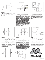
SETTING REEL SPEED
To achieve a consistent, high quality of cut, and a
uniform after-cut appearance, it is important that the
reel speed be matched to the height of cut.
Adjust the reel speed controls as follows:
1. Select the height-of-cut at which the cutting
units should be set.
2. Choose the desired ground speed best suited for
conditions.
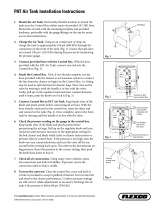
3. Using the appropriate graph (Fig. 19) for 5-
blade or 8-blade cutting units, determine the
correct reel speed setting.
4. To set reel speed, turn the knobs (Fig. 18), until
the indicator arrows are in line with the number
designating the desired setting.
Figure 18
1. Reel speed control knobs
Note: Reel speed can be increased or decreased to
compensate for turf conditions.
18
Operation
➀
➀
➀
➀

Figure 19
ADJUSTING LIFT ARM DOWN
PRESSURE
The down pressure spring on each cutting unit lift
arm can be adjusted to compensate for different turf
conditions. Increased down pressure will help keep
the cutting units on the ground when mowing at
higher speeds and helps maintain a uniform height-
of-cut in rough conditions or in areas of thatch
build-up.
Each down pressure spring may be adjusted to one
of four settings. Each increment increases or
decreases down pressure on cutting unit by 3 kg (8
lbs.).
1. Position the machine on a level surface, lower
the cutting units, stop the engine, engage the
parking brake and remove the key from the
ignition switch.
2. Remove the floor plate in front of the seat and
open the hood to gain access to all (5) springs.
3. Place an open end wrench on the hex shaft of
the spring bracket.
Figure 20
1. Spring bracket hex shaft
2. Retaining bracket
4. Remove the capscrew and locknut securing
retaining bracket while rotating hex shaft to
relieve spring tension.
5. Move the spring bracket to the desired location
and install the capscrew and locknut, while
turning the hex shaft to relieve spring tension.
TOWING THE TRACTION UNIT
If it becomes necessary to tow the machine, tow it
forward only and at a speed no greater than 16 kmh
(10 mph).
Note: If you exceed these towing limits, severe
damage to the hydrostatic transmission may occur.
To tow a disabled machine:
1. Loosen and remove the capscrews securing the
drive shaft to the engine. Loosen the capscrews
clamping the drive shaft to transmission (Fig.
19
Operation
6.4
9.5
12.7
15.9
19.0
7.9
11.1
14.3
17.5
7.9
11.1
14.3
17.5
6.4
34
567
34
567
89
10
9.5
12.7
15.9
19.0
P
o
s
itio
n
3
P
o
s
itio
n
4
P
o
s
itio
n
4
P
o
s
itio
n
5
P
o
s
itio
n
5
P
osition 6
P
osition 6
Position 7
P
o
s
itio
n
7
Position 8
Position 8
P
osition
9
P
o
s
itio
n
9
Position 10
Position 10
HEIGHT OF CUT (MM) HEIGHT OF CUT (MM)
MOWING SPEED (KMH)
MOWING SPEED (KMH)
5-BLADE REEL
8-BLADE REEL
2
4
1
5
9
7
8
3
6
Solenoid Power
Wire Color
1 Pink/Blue
2 Brown/White
3 Orange/Blue
4 Yellow/Black
5 Yellow/White
6 Orange/Red
7 Yellow/Blue
8 Black/Red
9 Brown/White
Solenoid Wire
Identification
Front Reel Speed Control
Rear Reel Speed Control
Springs are under tension, use caution when
adjusting.
CAUTION
➁
➀

20). Remove the drive shaft.
Important: If the drive shaft is not removed
before towing, severe damage to the
transmission may occur.
2. Attach a suitable chain, strap or cable to the
center of the front frame member (Fig. 22).
Figure 21
1. Drive shaft
Figure 22
1. Center of front frame member
Note: Lock both brake pedals together before
towing.
3. Attach the other end of the towing device to a
vehicle that is capable of towing the machine
safely at speeds below 16 kmh.
4. An operator must be on the machine to steer it
and keep the traction pedal fully depressed in
the forward position while towing.
5. When towing is completed, reinstall the drive
shaft as shown in Figure 21. (The splines are
designed to allow assembly only when the two
halves of the shaft are properly oriented.)
DIAGNOSTIC LIGHT (Fig. 23)
The RM 5200-D is equipped with a diagnostic light
that indicates if the electronic controller is
functioning correctly. The green diagnostic light is
located under the control panel, next to the fuse
block. When the electronic controller is functioning
correctly and the key switch is moved to the ON
position, the controller diagnostic light will be
illuminated. The light will blink if the controller
detects a malfunction in the electrical system. The
light will stop blinking and automatically reset when
the key switch is turned to the OFF position.
Figure 23
1. Electronic controller light
When the controller diagnostic light blinks, one of
the following problems has been detected:
1. One of the outputs has been shorted.
2. One of the outputs is open circuited.
Using the diagnostic display, determine which
output is malfunctioning; refer to Checking Interlock
Switches.
If the diagnostic light is not illuminated when the
key switch is in the ON position, the electronic
controller is not operating. Possible causes are:
1. Connector is not connected.
2. The light is burned out.
3. Fuses are blown.
4. Not functioning correctly.
20
Operation
➀
➀
➀
/