ENFORCER
®
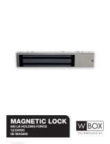
600-lb Electromagnetic Lock
4 SECO-LARM
®
U.S.A., Inc
Troubleshooting:
Door does not
lock
No power
Check to make sure the wires are securely
tightened to the terminal block.
• Check that the power supply is connected and
operating.
• Make sure the lock switch is wired correctly.
Status LED is
not illuminated
No power
Door locks, but
can be easily
forced open
Poor contact
between
electromagnet and
armature plate
Make sure the electromagnet and armature
plate are properly aligned.
• Make sure the contact surfaces of the
electromagnet and armature plate are clean
and free from rust.
Incorrect voltage
setting
Check the power leads with a meter, and make
sure 12VDC or 24VDC is present.
Delay in door
releasing
A secondary diode
was installed across
the electromagnet
The electromagnet is fitted with a metal oxide
varistor to prevent interference, so do not install
a secondary diode.
No relay output
No power
• Check that the power is connected and
operating.
• Make sure the lock is aligned properly.
• Make sure the NO/NC/COM are wired properly.
Misalignment
Delay in door
relocking
Check timer
Make sure timer is adjusted to desired delay
time.
Maintenance:
• Clean the contact surfaces of the electromagnet or armature plate with a soft cloth and non-
abrasive, non-corrosive cleaner.
• Apply a light coat of a silicon lubricant to prevent rust. Wipe away the excess.
• Check that the armature plate is securely attached to the door, yet can pivot slightly around the
armature screw.
• Check that the electromagnet is securely attached to the door frame.
WARRANTY ENFORCER Electromagnetic Locks are warranted against defects in material and
workmanship while used in normal service for a period of one (1) year from the date of sale to the
original customer. Our obligation is limited to the repair or replacement of any defective part if the unit
is returned, transportation pre-paid, to SECO-LARM.
NOTICE The information and specifications printed in this manual are current at the time of publication.
However, the SECO-LARM policy is one of continual development and improvement. For this reason,
SECO-LARM reserves the right to change specifications without notice. SECO-LARM is also not
responsible for misprints or typographical errors.
Copyright © 2010 SECO-LARM U.S.A., Inc. All rights reserved. This material may not be reproduced
or copied, in whole or in part, without the written permission of SECO-LARM.
SECO-LARM
®
U.S.A., Inc.
16842 Millikan Avenue, Irvine, CA 92606 Website: www.seco-larm.com
Tel: 800-662-0800 / 949-261-2999 Fax: 949-261-7326 E-mail: sales@seco-larm
.com
600-lb Electromagnetic Lock Series
Manual
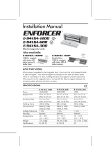
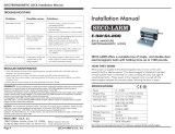
How it works
When power is applied to the magnetic lock, it turns on the unit's powerful built-in
electromagnet. This electromagnet is attracted to the steel armature plate which is mounted on
a door, holding the door fast against unauthorized entry. When power to the magnetic lock is
turned off, the electromagnet releases the armature plate, allowing the door to open. In
addition, the E-941SA-600PQ & E-941DA-600PQ have built-in LEDs to show electromagnet
status, plus a status sensor to monitor whether the door is securely closed.
Note: Products with model numbers that end with “Q” or that have a round green “Q” sticker are RoHS compliant.