4
Programming Interface:
• All codes are four (4) digits in length.
• Entry code is a four (4) digit code needed to activate the gate.
• Master Code is needed to add, remove or reset entry codes.
• Master Code also functions as the entry code under normal
operation.
• Factory default Master Code is 1234.
• STATUS light should blink and beeper should beep (once)
whenever any button is pressed.
• If more than 10 seconds elapsed between key presses the unit
returns to normal (idle) operating mode.
• Keypad can only enter program mode from sleep mode
(keypad is turned OFF).
• Keypad will beep three times before going into sleep mode.
Program New Master Code:
• Press and release PROGRAM button.
• Enter the old Master Code then press and release PROGRAM
button.
• Enter 0, 6 then press and release PROGRAM button
• Enter the new Master Code then press and release PROGRAM
button.
• Enter the new Master Code then press and release PROGRAM
button again for confirmation.
• Beeper beeps 3 times to conrm that the new Master Code is
accepted.
NOTE: If the Master Code is not a matched pair or error occurs,
(i.e. if the entry code is NOT a 4-digit code) the STATUS light
will flash rapidly and the beeper will sound for 2 seconds before
returning to normal operation with old Master Code.
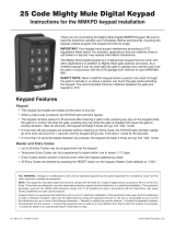
Example: Key press sequence to change old Master Code from
1 2 3 4 to 3 1 2 1
1 2 3 4 0 6 3 1 2 1 3 1 2 1
The round black dot is the ‘PROGRAM’ button.
Program (Add) New Entry Code:
• Press and release PROGRAM button.
• Enter the Master Code then press and release PROGRAM
button.
• Enter 0, 2 then press and release PROGRAM button.
NOTE: If memory is full (all 100 locations are already
programmed) the STATUS light will flash rapidly and the
beeper will sound for 2 seconds before returning to normal
operation without saving.
• Enter the new Entry Code then press and release PROGRAM
button.
• Beeper beeps 3 times to conrm that the new Entry Code is
accepted.
NOTE: If the code is NOT 4-digits in length or an error
condition has occurred. The STATUS light will flash rapidly
and the beeper will sound for 2 seconds before returning to
normal operation without saving.
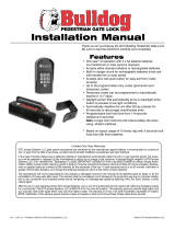
Example: Key press sequence to add ‘3456’ as a new entry
code. (1234 is the Master Code)
The round black dot is the ‘PROGRAM’ button.
Program (Add) New Temporary Entry Code:
• Press and release PROGRAM button.
• Enter the Master Code then press and release PROGRAM
button.
• Enter 8, and any number between 1 thru 7 then press and
release the PROGRAM button. The number 1 thru 7 indicates
the number of days after which the code will be automatically
removed from memory
NOTE: If memory is full (all 100 locations are already
programmed) or an invalid entry is detected, then an error
condition has occurred. The STATUS light will flash rapidly
and the beeper will sound for 2 seconds before returning to
normal operation without saving.
• Enter the new Entry Code then press and release PROGRAM
button.
• Beeper beeps 3 times to conrm that the new Entry Code is
accepted.
NOTE: If the code is NOT 4-digits in length or an error
condition has occurred, the STATUS light will flash rapidly
and the beeper will sound for 2 seconds before returning to
normal operation without saving.
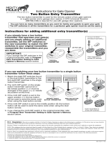
Example: Key press sequence to add “3456” as a new entry
code that will remain valid for 2-days only. (1234 is the
Master Code)
The round black dot is the ‘PROGRAM’ button.
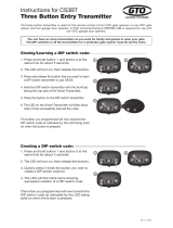
Example: Key press sequence to add “3456” as a new entry
code that will remain valid for 7-days only. (1234 is the
Master Code)
The round black dot is the ‘PROGRAM’ button.
Programming the Keypad
Delete An Entry Code:
• Press and release PROGRAM button.
• Enter the Master Code then press and release PROGRAM
button.
• Enter 0, 3 then press and release PROGRAM button.
• Enter the Entry Code to be deleted then press and release
PROGRAM button.
• Beeper beeps 3 times to conrm that the new Entry Code is
deleted.
NOTE: If no matching code is found or the code is NOT 4-digit
in length, then an error condition has occurred. The STATUS
light will flash rapidly and the beeper will sound for 2 seconds
before returning to normal operation without saving.
Example: Key press sequence to delete entry code ‘3456’ from
memory. (1234 is the Master Code)
The round black dot is the ‘PROGRAM’ button.
1 2 3 4 0 2 3 4 5 6
1 2 3 4 8 2 3 4 5 6
1 2 3 4 0 3 3 4 5 6
1 2 3 4 8 7 3 4 5 6