Page is loading ...

Introduction ........................................1
Specifications ......................................1
Capacity Selection Guide ..................2
Output Capacity ..................................3
Installation
Location Selection ........................4
Physical Installation ......................5
Electrical Installation ....................7
Start Up ........................................8
Operation ..........................................9
Maintenance
To Clean and Inspect ..................10
To Check for Leaks......................10
To Clean Spray Nozzle................11
To Clean Solenoid Valve ............12
Unit Diagram and Parts List ............13
Warranty ..............................Back cover
Manual for:
• Installation
• Operation
• Maintenance
Duct Mount
Atomizing Humidifier
Table of Contents
252903-001 7/16/04
CAUTION: Read installation,
operation, and maintenance
instructions carefully for safe
operation. Exercise the usual
precautions when working
with electricity.
Mister 50 (24V)
Mister 50-1

1
SPECIFICATIONS
Model Mister 50/Mister 50-1
Type of Unit Atomizing
Duct Mounting Supply
GPD @ 140° 11.0
GPD @ 120° 11.0
GPD @ 100° Not recommend for heat pumps
Voltages 24V, 120V
Unit Dimensions 6” W x 2 3/4” D x 6” H
Duct Opening 5” W x 5 3/8” H
Shipping Weight 3 lbs.
Standard Equipment • Wall/Duct Mount Humidistat
• Self Piercing Saddle Valve
• 10’ Plastic Water Tubing
Features • Tilt-out Mounting
• .75 GPH Hollowcone Oil Nozzle w/
Stainless Steel 100 Mesh Filter Screen
• Patented Multi Position Adjustable Nozzle
•Two Year Warranty
Specifications
Introduction
The benefits of a properly humidified environment (35-
50% Relative Humidity) are many. They include both
personal comfort as well as the preservation of
furniture, draperies, carpets, wooden floors and
cabinets, paintings, pianos, etc.
Your home will be more comfortable at a lower
temperature (i.e.: 68° F) at 30-40% Relative Humidity
(RH) than at 71° to 72° F without controlled humidity.
Since every degree of temperature setback represents
about 3% of your heating costs, this can possibly
represent a significant annual savings.
During the heating season, cold air is brought into the
home and heated. When heated, this air dries out and
greatly increases its capacity to hold more moisture. By
using a humidifier, a source of water is provided to
satisfy this increased moisture holding capability,
rather than having it drawn from our body surface and
the surrounding furnishings in the home.
Introduction

2
Sq. Footage of
Home
1000
1500
2000
2500
3000
4000
Tight Home
(GPD)
0.5
3.0
5.0
7.5
10.0
14.5
Average Home
(GPD)
5.0
10.0
14.0
19.0
23.5
33.0
Loose Home
(GPD)
10.0
16.5
24.0
30.5
37.5
51.5
Air Tightness of Home
The above calculations are for reference only and are based on the following:
• Inside temperature 70° F/35% Relative Humidity
• Outside Temp 20° F /70% Relative Humidity
• 8 foot ceiling height
• Internal moisture gain of one pound per hour
• Furnace on-time of 70%
This chart uses A.R.I. standard designations:
A “Tight Home” is assumed to be well insulated with vapor barriers, tight storm windows and
doors, and a dampered fireplace. Air exchange rate of .5 changes per hour.
An “Average Home” is insulated and has a dampered fire place, but there are no vapor barriers,
storm doors, or storm windows. Air exchange rate of 1.0 change per hour.
A “Loose Home” is generally one constructed before 1930, has little or no insulation, no storm
doors, storm windows, weather stripping or vapor barriers, and often no effective dampering of
fireplaces. Air exchange rate is as high as 1.5 changes per hour.
Capacity Selection Guide

3
Output Capacity
Increasing or decreasing the nozzle size or
water pressure to the humidifier can vary the
output capacity of this humidifier. It is
recommended that the humidifier not be
used at water pressures below 40 PSI,
otherwise, the mist may be affected.
The following chart illustrates the capacity of
different nozzles at varying water pressures.
The output capacities shown are for water,
and are 1/2 the output capacity of the rated
oil nozzles. 1.00 oil = .50 water
Oil Nozzle 40 PSI 50 PSI
size GPH GPD GPH GPD
.37 .185 4.44 .225 5.44
.50 .250 6.00 .300 7.20
.75 .375 9.00 .445 10.68
1.0 .500 12.00 .600 14.40
WATER PRESSURE
Oil Nozzle 80 PSI 100 PSI
size GPH GPD GPH GPD
.37 .275 6.60 .300 7.20
.50 .350 8.40 .400 9.60
.75 .550 13.20 .600 14.40
1.0 .700 16.80 .800 19.20
WATER PRESSURE
This humidifier comes standard with a hollow
cone pattern .75 GPH nozzle, however,
additional nozzles may be purchased from
your local plumbing distributor or hardware
store. If the water pressure fluctuates or is
excessive, a small pressure regulator should
be installed in the water line supplying the
humidifier.
Output Capacity
Note:
Due to the operation cycle of the
furnace and humidifier, it may take
anywhere from 2 to 5 days to reach
the proper humidification level.

4
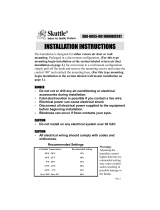
Selecting a Location for the Unit
When selecting a location for the installation
of your humidifier, certain conditions must be
met for its proper operation. The
recommended location for this humidifier is
on the supply plenum, approximately 3”
downstream of the furnace. In narrow
plenum arrangements, the humidifier should
be mounted on the narrow side of the duct.
Select a location so that the spray from the
nozzle will not impinge on the furnace fan,
control switches, air conditioning or heat
coils.
The humidifier should be mounted so that
the furnace air carries the mist away from the
humidifier thermostat. The unit is specially
designed to allow the nozzle to be adjusted
so that the thermostat can be located
upstream from the nozzle. For plenum
mounting, the nozzle should always be
pointed in the up position. When the position
of the nozzle has been determined, tighten
the nozzle/solenoid valve mounting hardware
securely.
Installation
Supply
Plenum
Humidifier
Nozzle
Nozzle/Solenoid
Mounting
Hardware
Supply
Plenum
Humidifier
Nozzle
Thermostat
Furnace
Supply Plenum
Humidifier
Nozzle
Thermostat
Furnace
Supply Plenum
Humidifier
Nozzle
Thermostat
Furnace
DO NOT install the humidifier where freezing
conditions could occur or where accidental
overflow could cause water damage to the
home or property.
DO NOT install the humidifier where the
temperature will exceed 180° F. Excessive heat
may cause softening and distortion of the
plastic housing.
The installation of a water filter may reduce
the potential clogging of the nozzle and
solenoid valve in hard water applications
.

5
Installation
Physical installation
Remember to select a location that is
readily accessible for periodic inspection
and cleaning of your humidifier.
1. Read the instructions carefully prior to
installing this product to ensure safe
operation. Failure to follow these
instructions could damage the humidifier or
cause a hazardous condition.
2. Check the ratings given on the product to
make sure it is suitable for your application.
3. Tape the template (found in the parts bag)
in place on the duct and punch the (4) holes
as marked. Also punch holes at the (4)
corners of the cut out to use as reference
points.
4. Drill the (2) 1/8” diameter holes at the top of
the template.
5. Drill the (2) 7/32” diameter holes at the side
(bottom).
6. Neatly cut out the duct as shown on the
template.
7. Remove all sharp edges and burrs to prevent
damage to the unit or injury to yourself.
8. Remove the Retainer and (4) sheet metal
screws from the parts bag.
9. Carefully place the Retainer inside the duct
and fasten loosely with (1) screw.
10. Place the bottom lip of the humidifier on the
bottom edge of the cut out.
11. Slide the Retainer over the lip and secure
with (1) sheet metal screw at the other side.
12. Tighten both screws securely to fasten the
unit into place.
13. The unit should now hinge up easily and
align with the holes drilled at the top.
14. Remove the foam seal from the parts bag,
remove the paper backing and place on the
sheet metal around the cut out opening to
seal the humidifier.
15. Tilt the humidifier into position and fasten
with (2) sheet metal screws.
CAUTION:
Only a trained service person
should install this humidifier. Do
not connect the unit to power
source until installation is
complete. A thorough checkout
of the unit installation should be
completed before operation.
Failure to follow these directions
may void the manufacturer's
original warranty.
Duct Cut-Out
Retainer
Screw
Humidifier
Foam Seal
Screws

6
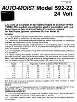
16. Install the saddle valve (from parts bag) per
instructions printed on valve packaging.
17. Place the compression nut on one end of the
water tubing, with the threads facing toward
the tubing end.
18. Slide the Delrin sleeve (from parts bag) over
the tubing with the short beveled end toward
the nut. Leave 5/32” of tubing protruding
beyond the end of the delrin sleeve.
19. Press the insert (from parts bag) into the water
tubing. If the tubing is too small to allow the
insert to enter, place the end of the tubing in
hot water to soften the plastic. Place the insert
against a flat surface and press the tubing
onto the insert.
20. Fasten tubing assembly securely to the saddle
valve, but do not connect to humidifier.
21. With the end of the tubing in a bucket or pan,
turn on the saddle valve to void the tubing
assemblly of any debris.
22. Cut off any excess length of water tubing and
connect it to the humidifier using the
compression nut, sleeve and insert as defined
in steps 17, 18, and 19 above.
23. Turn the saddle valve on and check the tubing
and humidifier for leaks.
Installation
Humidifier
Delrin Sleeve
Saddle Valve
Water Line
Compression Nut
Insert
Insert
Water connection

7
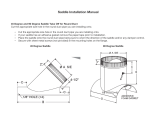
ELECTRICAL INSTALLATION
This humidifier is intended to be wired directly
to the integrated control panel on your furnace.
The electrical tap will provide power to the
humidifier whenever the circulating air blower
is in operation.
Read the instructions in the furnace installation
manual carefully before attempting installation
or operation of the humidifier. Failure to follow
these instructions may result in improper
installation and therefore, void the
manufacturer's warranty.
Installation
Fan
Limit
Transformer
Fan
Motor
Humidistat
Thermostat
Mister 50 (24v)
Humidifier
Solenoid
Valve
Electrical connections (24v)
Fan
Limit
Fan
Motor
Humidistat
Thermostat
Mister 50-1 (120v)
Humidifier
Solenoid
Valve
Electrical connections (120v)
WARNING
Improper electrical wiring
can cause personal shock,
personal injury, or
property damage. It is required
by local codes that the unit be
installed by a properly qualified
HVAC technician or electrician.
All wiring must be in accordance
with NEC and existing local
codes.
Humidistats provided with the Mister 50 (24V) are designed for operation on
24V AC electrical systems and must be wired as defined below.
Humidistats provided with the Mister 50-1 (120V) are designed for operation
on 120V AC electrical systems and must be wired as defined below.

8
Note:
It may take several days for the
humidity level in the home to reach
comfortable levels.
Installation
Start Up
1. Adjust the humidistat to the ON position
and turn the furnace on.
2. Adjust the house thermostat to cause the
furnace to operate. The burner and
blower should turn on BEFORE the
humidifier.
3. The solenoid valve will make an audible
click when it operates, either on or off.
4. If necessary, adjust the furnace fan control
to a lower setting to allow the blower to
turn on befor
e the humidifier turns on
and the blower turns off after
the
humidifier is off.
5. Readjust the humidistat to the desired
setting (30-40% Relative Humidity is
recommended).
6. If condensation occurs on windows, lower
the humidistat setting until the
condensation has disappeared.

9
Operation of Humidifier
Your atomizing mister type humidifier
operates by dispersing a fine mist into the
warm air plenum of your furnace. The water
is then evaporated and carried into the home
by the furnace air flow. This humidifier is
recommended for areas where water mineral
content is low. Otherwise, a fine accumulation
of white dust may occur in either the ducts or
living areas. High mineral content will also
clog the nozzle causing an uneven spray
pattern or excessive dripping.
When wired properly, the humidifier will
operate only when the plenum temperature
rises to the internal thermostat setting, the
humidistat senses a need for humidity, and
the furnace blower is in operation. The
internal thermostat indicates the temperature
at which the humidifier will turn on. The
humidifier should activate after the furnace
blower comes on and shut off before the
furnace blower turns off. If this does not
occur, readjust the furnace fan switch as
required.
If applicable, set the humidistat in the
recommended range of 30-40% Relative
Humidity for automatic humidity control
during the heating season (a lower setting
may be used to control condensation on
single pane windows). Due to the operation
cycle of the furnace and humidifier, it may
take two to five days to reach the proper
humidification level.
Recommended Relative
Humidity Levels vs.
Temperature
Outside Recommended
Temperature Relative
(°F) Humidity %
40 45
30 40
20 35
10 30
025
Note:
When shutting the humidifier down for
the summer months turn the water off
and clean any mineral accumulation
from the unit. Leave the water turned
off. If the furnace fan is to be used for
cooling purposes, disconnect power to
the humidifier or turn the humidistat to
the OFF position if applicable.
Operation

10
Like your heating system and air conditioning
unit, periodic maintenance and cleaning are
required to ensure the safe and efficient
operation of your humidifier.
To improve the efficiency of your humidifier, and
to reduce the possibility of a health hazard, it is
recommended that you take the following
precautions:
• Follow the manufacturer’s recommended
cleaning and maintenance instructions.
• The amount of minerals and other impurities
in a water source can vary greatly, therefore
the frequency of cleaning the humidifier
also varies.
• During the heating season, check for film or
scale build-up on the atomizing nozzle and
drip sleeve on a monthly basis. Establish a
proper cleaning schedule to ensure the
efficiency of the humidifier.
• At the end of the winter humidification
season, drain and thoroughly clean the
humidifier.
Note:
The necessity to clean your
humidifier is substantially the
result of impurities coming in
through your water supply
which feeds the humidifier.
Other household dust,
containing biological and
microbial contaminants can
find its way into the air
handling system and
ultimately, the humidifier.
The humidifier is not the
source of these impurities.
Maintenance
To check for leaks:
1. Turn the furnace and
humidistat on and ensure
that the humidifier has
operated for at least (1)
minute.
2. Remove the screws from
the top of the unit and
check the nozzle for
leakage.
3. If there is no leakage,
return the unit to its
original position and secure
with screws.
4. After completing the
cleaning, operate the
solenoid to be sure it is
operating properly.
To inspect and clean the unit:
1. Turn the power to the furnace OFF.
2. Turn the humidistat to the OFF position.
3. Turn the water off at the saddle valve and
remove the water line compression nut
from the humidifier.
4. With the open end of the water line
directed into a bucket or pan, turn on the
water at the saddle valve to void the water
line of any debris or particulates.
5. Remove the screws from the top of the unit
and swing the unit down to gain access to
the nozzle.
6. Remove the drip sleeve from around the
nozzle and clean in a 50/50 solution of
vinegar and water.
7. Carefully remove the nozzle from the
adapter.
8. Replace the spray nozzle with one of the
same size and capacity as initially provided
with the unit. Tighten securely and replace
the drip sleeve around the nozzle.
9. Swing the unit into place and fasten with
screws.
10. Restore the water supply to the humidifier
by reversing step 3.

11
If the power to the solenoid valve coil is correct, the
following symptoms indicate that the spray nozzle
requires cleaning:
• Larger spray pattern
• Non symmetrical spray pattern
• Constant water stream
• Not spraying water
To Clean the Spray Nozzle
1. Turn the power to the furnace OFF.
2. Turn the humidistat to the OFF position.
3. Turn off the water supply at the saddle valve.
4. Disconnect the power and water lines from the
humidifier.
5. Remove the humidifier from the duct.
6. Remove the drip sleeve from the spray nozzle.
7. Hold the nozzle adapter with a 3/4” wrench and
using a 5/8” wrench, turn the spray nozzle counter
clockwise and remove the components.
8. Remove the screen from the nozzle by turning it
counter clockwise.
9. Holding the spray nozzle with the 5/8” wrench,
insert a 5/32” allen wrench into the set screw and
turn it counter clockwise and remove the
components.
10. Rinse and clean all parts. Suggested cleaners
include 50/50 solution of white vinegar and water
or liquid humidifier cleaner.
11. Using a razor blade, carefully clean the (4) slots on
the director (see diagram below). The director is
the part that provides a fine spray pattern.
12. Reassemble the nozzle assembly, paying careful
attention to the diagram below for the correct
replacement of parts.
13. After completing the assembly, operate the unit to
be sure it is functioning properly.
Maintenance
NOTE:
Be careful not to over
tighten the nozzle
assembly. It should be a
snug fit.
NOTE:
Assemble the nozzle to
the adapter so that it
will not leak.
NOTE:
It is recommended that
the nozzle be replaced
on an annual basis to
avoid mineral build up
and possible clogging.
Nozzle
Adapter
(Brass)
Screen Retainer
(Brass)
Screen
(Stainless)
Set Screw
(Stainless)
Sleeve
(Stainless)
Director
(Stainless)
O-Ring
(Rubber)
Nozzle Head
(Stainless)

12
If the power to the solenoid valve coil
is correct, the following symptoms
indicate that cleaning the solenoid
vavle is required:
• Sluggish valve operation
• Excessive noise
• Constant water spray
• Streaming water
To clean the solenoid valve:
1. Turn the power to the furnace OFF.
2. Turn the humidistat to the OFF
position
3. Turn off the water supply at the
saddle valve
4. Disconnect the power and water
lines from the humidifier
5. Remove the humidifier from the
duct.
6. Remove the drip sleeve from the
nozzle assembly.
7. Using a 3/4” wrench, remove the
nozzle adapter.
8. Remove the solenoid valve
assembly from the case using a
Phillips head screwdriver.
9. Remove the brass nipple from the
OUT port of the valve body.
Remove the street elbow and brass
adapter from the IN port of the
valve.
10. Remove the filter from inside the
inlet brass adapter using a small
nail or paperclip.
Note: Be careful not to
puncture the filter.
11. Remove the coil from the assembly
by turning the valve body counter
clockwise.
12. Clean and remove all particulates
from the brass fittings, filter,
plunger/spring assembly and
orifices in the valve body using a
50/50 solution of white vinegar
and water or a liquid humidifier
cleaner.
13. Reassemble the parts, paying
careful attention to the diagram
below for the correct placement.
14. After completing the assembly,
operate the unit to be sure it is
functioning properly.
Maintenance
NOTE: Teflon tape may be used on the threads for
re-assembly, however, do not use pipe dope, as it
will clog the nozzle assembly.
Coil
IN
OUT
O-Ring
(Rubber)
Valve
Body
(Brass)
Brass Nipple (To Nozzle Adapter)
Street
Elbow
Brass
Adapter
Filter
To Water Tubing
Plunger/Spring
Assembly

13
Unit Diagram
9
8
13
10
11
12
20
Humidifier
20
19
17
19
15
18

14
Parts list
Model Mister 50 Mister 50-1
Assembly Part Number 351367-101 351367-102
Item Descripton P/N P/N
1 Drip Sleeve 12018 12018
2 Nozzle 12006-001 12006-001
3 O-Ring 160 160
4 Adapter 12007-002 12007-002
5 Nipple 12008 12008
6 Slide 12012 12012
7 Case 12001 12001
8 Thermostat 12005 12005
9 Solenoid (24 volt) Valve Assembly G-109 -
9a Solenoid (120 volt) Valve Assembly - 12004-002
10 Street Elbow 12009 12009
11 Adapter, Brass G-157 G-157
12 Filter, Conical G-125 G-125
13 Cover 12002 12002
14 Humidistat 24 volt (not shown) 352680-004C –
14a Humidistat 120 volt (not shown) - 352680-002C
15 Plastic Tubing 1/4” OD 2413A 2413A
150 PSI (Per foot)
16 Brass Compression Sleeve (2) *† FV-11 FV-11
17 Brass Compression Nut (2) † FV-12 FV-12
18 Saddle Valve † IN-2ST IN-2ST
19 Insert (2) † EST-133 EST-133
20 Delrin Sleeve (2) † EST-163 EST-163
21 Retainer (not shown) † 12003 12003
* For use with copper water line connections
† Located in Parts Bag

15
Warranty
Humidifier Limited Two Year Warranty
This limited warranty covers Herrmidifier Residential Type Humidifiers, excluding duct work, wiring and
installation. The manufacturer warrants that all new Herrmidifier Humidifiers are free from defects in material
and workmanship under normal, non-commercial use and service. The manufacturer will remedy any covered
defects if they appear within 24 months from the date of original installation as evidenced by proof of
purchase, subject to the terms and conditions of this Limited Two-Year Warranty stated below:
1. THIS LIMITED TWO-YEAR WARRANTY is granted by CareCo, 415 W. Wabash Ave., P.O. Box 200,
Effingham, IL 62401.
2. This warranty shall extend only to any non-commercial owner who has purchased the residential
humidifier other than for purposes of resale.
3. All components are covered by this limited warranty except expendable items, such as evaporative pads,
media filter pads and nozzles.
4. If, within the warranty period, any Herrmidifier residential humidifier unit or component requires
service, it must be performed by a competent heating and/or air conditioning contractor (preferably the
installing contractor). CareCo will not pay shipping charges or labor charges to remove or replace such
defective parts or components. If the part or component is found by inspection to contain such defective
material and workmanship it will be either repaired or exchanged free of charge at CareCo's option,
and returned freight collect.
5. In order to obtain the benefits of this limited two-year warranty, the owner must notify the dealer or
distributor of any defect within 30 days of its discovery. If after reasonable time you have not received
an adequate response from the dealer or distributor, notify in writing CareCo Service Dept., 415
Wabash Ave., P.O. Box 200, Effingham, Illinois, 62401, or call 1-866-829-2440 or email
[email protected]. Humidifiers which have been installed or become part of real
estate cannot be returned. CareCo will receive, freight prepaid, only removable parts or components of
such defective humidifiers.
6. This limited warranty does not apply to any part or component that is damaged in transit or in handling,
has been subject to misuse, neglect or accident; has not been installed, operated and serviced according
to Herrmidifier's instructions; has been operated beyond the factory rated capacity; or altered in any
such way that its performance is affected. There is no warranty due to neglect, alteration or ordinary
wear and tear. Herrmidifier's liability is limited to replacement of defective parts or components and
does not include the payment of the cost of labor charges to remove or replace such defective
components or parts.
7. CareCo will not be responsible for loss of use of any product; loss of time, inconvenience, or any other
indirect, incidental or consequential damages with respect to person or property, whether as a result of
breach of warranty, neglect or otherwise. SOME STATES DO NOT ALLOW THE EXCLUSION OR
LIMITATION OF INCIDENTAL OR CONSEQUENTIAL DAMAGES, SO THE LIMITATION OR EXCLUSION IN THE
PRECEDING SENTENCE MAY NOT APPLY TO YOU.
8. THIS WARRANTY GIVES YOU SPECIFIC RIGHTS, AND YOU MAY ALSO HAVE OTHER RIGHTS WHICH VARY
FROM STATE TO STATE.
9. Any warranty by CareCo of merchantability, fitness for use or any other warranty (express, implied or
statutory), representation or guarantee other than those set forth herein, shall expire at the expiration
date of this express limited warranty. SOME STATES DO NOT ALLOW LIMITATIONS ON HOW LONG AN
IMPLIED WARRANTY LASTS, SO THE LIMITATION IN THE PRECEDING SENTENCE MAY NOT APPLY TO
YOU.
10. Herrmidifier reserves the right to make changes in the design and material of its products without
incurring any obligation to incorporate such changes in units completed on the effective date of such
change.
CareCo Service Dept.,
415 Wabash Ave., P.O. Box 200, Effingham, Illinois, 62401
Phone: 1-866-829-2440
E-mail: [email protected]
/