3M Cold Shrink QS-III Splice 5515A-350-AL, UniShield®, Longitudinally Corrugated, 15 kV, 350 kcmil, 1/case Operating instructions
- Category
- Signal cables
- Type
- Operating instructions
This manual is also suitable for
- Cold Shrink QS-III Splice 5515A-350-CU, UniShield®, Longitudinally Corrugated, 15 kV, 350 kcmil, 1/case
- Cold Shrink QS-III Splice 5515A-500-AL, UniShield®, Longitudinally Corrugated, 15 kV, 500 kcmil, 1/case
- Cold Shrink QS-III Splice Kit 5515A, Longitudinally Corrugated Shield, 15 kV, Standard, 1/case
- Cold Shrink QS-III Splice Kit 5515A-500-CU, 15 kV, Standard, 1/case
- Cold Shrink QS-III Splice Kit 5515A-750-AL, 15 kV, Standard, 1/case
- Cold Shrink QS-III Splice Kit 5515A-750-CU, 15 kV, Standard, 1/case

3M
™
Cold Shrink Splice Kit QS-III
5515A
for UniShield
®
, Wire Shielded, Longitudinally Corrugated (LC),
and Tape Shielded (Ribbon Shielded) Cable or Transitions to
Concentric Neutral (CN)/Jacketed Concentric Neutral (JCN) Cables
Instructions
IEEE Std. 404
15 kV Class
150 kV BIL
CAUTION
Working around energized systems may cause serious injury or death. Installation should
be performed by personnel familiar with good safety practice in handling electrical
equipment. De-energize and ground all electrical systems before installing product.
Kit Selection Table
Kit Number Cable Insulation O.D. Range Conductor Size Range
5515A
1.04"–1.70"
(26,4–43,2 mm)
350–750 kcmil*
(185–325 mm
2
)
* Splices (including size transitions) can be made to smaller or larger conductors (but larger conductors may require special neutral
handling), provided both cables are within the Insulation O.D. Range and the connector meets the dimensional requirements
shownbelow.
Connector Dimensional Requirements
Minimum Inches (mm) Maximum Inches (mm)
Outside Diameter 0.80" (20,3 mm) 1.84" (46,7 mm)
Length
Aluminum (Al/Cu) Compression
—
6.75" (171 mm)
Length
Copper Compression and 3M
™
Shearbolt Connector
QCI 350-750
—
7.50" (191 mm)
March2011
78-8124-5934-1-E 3

2 78-8124-5934-1-E
1.0 Kit Contents
a. 3M
™
ColdShrinkSpliceBody5417A(1ea.)
b. ColdShrinkJacketingTube(1ea.)
c. ColdShrinkAdapterTube(1ea.)
d. ShieldingSleeve,1/3NeutralMaximum(1ea.)
e. GroundStrap(1ea.)
f. ConstantForceSpringGroundConnectors(5ea.)
g. RedCompoundTubes(non-siliconegrease)(2ea.)
h. Scotch
®
MasticSealingStrips2230,6"length(6ea.)
i. Scotch
®
RubberMasticTape2228Rolls,2"x36"(2ea.)
j. CopperFoilTape,1/2"x10"(2ea.)
k. 3M
™
CableCleaningPadsCC-3(1ea.)
l. CablePreparationTemplate(1ea.)
m.InstructionBooklet(1ea.)
Note: Donotuseknivestoopenplasticbags.
Note: Connectornotshown,butifincluded,itisindicatedonthepackaginglabel.
Note: Item“C,”ColdShrinkAdapterTube,maynotbeincludedinallkits.

78-8124-5934-1-E 3
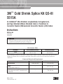
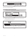
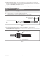
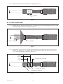
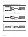
2.0 Prepare Cables
2.1 For Tape, LC, Wire Shield or UniShield
®
Cable:
2.1.1 Preparecablesaccordingtostandardprocedures.Refertotemplateprovidedorillustrationbelowfor
properdimensions.(Figure1).
8 1/4"
(210 mm)
14 3/4"
(375 mm)
3 1/2"
(89 mm)
Cable Jacket
Metallic
Shield
Semi-con
Insulation
8 1/4"
(210 mm)
14 3/4"
(375 mm)
3 1/2"
(89 mm)
Cable Jacket
Wire Shield
Semi-con
Insulation
8 1/4"
(210 mm)
14 3/4"
(375 mm)
Insulation
Shield Wires
3 1/2"
(89 mm)
Tape & LC Shielded Cables
Wire Shielded Cable
UniShield
®
Cable
Figure1
Note: CablesmustbewithintheinsulationO.D.rangeofthesplicekitandtheconnectormustmeetthe
dimensionalrequirementsshownonthefrontpage.

4 78-8124-5934-1-E
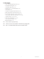
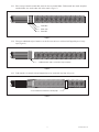
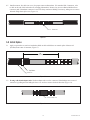
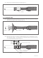
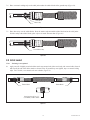
2.1.2 For Tape shield and LC shield: Secureendofeachmetallicshieldwithacoppertapestrip.
For Wire shield and UniShield
®
:Carefullybendshieldwiresbackovercablejacketsandtemporarily
securewithvinyltape.(Figure2).
Tape & LC Shielded Cables
Wire Shielded Cable
UniShield
®
Cable
Foil Tape
Semi-con
Semi-con
Metallic Shield
Cable Jacket
Semi-con
Cable Jacket
Vinyl Tape Shield Wires
Cable Jacket
Vinyl Tape Shield Wires
Vinyl TapeNeutral Wires
Figure2
Gotosection3.0“ParkSpliceComponents.”ifnottransitionsplicingtoJCNorCNcable.
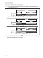
2.2 For Transitions to Jacketed Concentric Neutral (JCN) Cable:
2.2.1 Preparecablesaccordingtostandardprocedures.Refertotemplateprovidedorillustrationbelowfor
properdimensions(Figure3).
8 1/4"
(210 mm)
14 3/4"
(375 mm)
Neutral Wires
Semi-con
Insulation
8 1/4"
(210 mm)
14 3/4"
(375 mm)
Neutral Wires
Semi-con
Insulation
Concentric Neutral (CN)
Jacketed Concentric Neutral (JCN)
Figure3
Note: CablesmustbewithintheinsulationO.D.rangeofthesplicekitandtheconnectormustmeetthe
dimensionalrequirementsshownonthefrontpage.

78-8124-5934-1-E 5
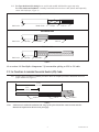
2.2.2 Carefullybendneutralwiresbackoveredgeofcablejacketandtemporarilysecurewithvinyltape.
Tape & LC Shielded Cables
Wire Shielded Cable
UniShield
®
Cable
Foil Tape
Semi-con
Semi-con
Metallic Shield
Cable Jacket
Semi-con
Cable Jacket
Vinyl Tape Shield Wires
Cable Jacket
Vinyl Tape Shield Wires
Vinyl TapeNeutral Wires
Figure4
Gotosection3.0“ParkSpliceComponents.”
2.3 For Transitions to Concentric Neutral (CN) Cable:
2.3.1 Preparecablesaccordingtostandardprocedures.Refertotemplateprovidedorillustrationbelowfor
properdimensions(Figure5).Do not cut neutral wires on CN cables.
8 1/4"
(210 mm)
14 3/4"
(375 mm)
Neutral Wires
Semi-con
Insulation
8 1/4"
(210 mm)
14 3/4"
(375 mm)
Neutral Wires
Semi-con
Insulation
Concentric Neutral (CN)
Jacketed Concentric Neutral (JCN)
Figure5
Note: CablesmustbewithintheinsulationO.D.rangeofthesplicekitandtheconnectormustmeetthe
dimensionalrequirementsshownonthefrontpage.
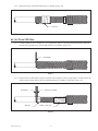
2.3.2 Cleancablesemi-conasshown(Figure6).
Binder Wire
Folded Back Neutral Wires
Semi-Con
Clean
Figure6

6 78-8124-5934-1-E
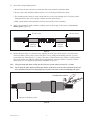
2.3.3 Placeastripofmasticaroundcablesemi-connexttoneutralbinder.Foldneutralsintomasticandplace
anotherbinderwireontheothersideofthemastic(Figure7).
Binder Wire
Mastic Strip
Binder Wire
Figure7
2.3.4 Wraptwoadditionalstripsofmasticoverthefirstoneandcoverwithtwohalflappedlayersofvinyl
tape(Figure8).
2 additional mastic strips covered with 2 layers vinyl tape
Figure8
2.3.5 Foldneutralsovermasticsealandtemporarilysecureendswithvinyltape(Figure9).
Secure folded-back neutral wires with vinyl tape
Figure9

78-8124-5934-1-E 7
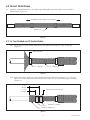
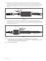
3.0 Park Splice Components
3.1 Cleanorcovercablejacketifnecessary,forcoldshrinkparkingposition.Slidejacketingtubeontoonecable
end.Slidesplicebodyontooppositecable,loosecoreendfirst.Forsizetransitions,parkspliceonsmallercable
(Figure10).
Note: Jacketingisnotoptional.Coldshrinkjacketingtubemustbeinstalled.
Loose Core End
Splice Body
Jacketing Tube
Figure10
Note: Ifspaceislimited,thejacketingtubeandsplicebodycanbeputonthecablestackedinsideeachother.
3.2 Positiontheexpandedshieldsleeveontoonecable.Theshieldsleeveisdesignedtocarryupto1/3neutral
current(Figure11).
Expanded Shield Sleeve
Figure11

8 78-8124-5934-1-E
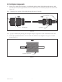
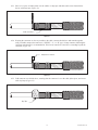
4.0 Install Connector
Note: Ifusingacrimp-typeconnector,gotostep4.3.
4.1 If using a 3M
™
Shearbolt Connector QCI 350-750, refertotheinstructionsincludedwiththeconnectorfor
insulationcut-backdimension.Insulationremovallengthshallnotexceed33/4"(95mm)fromconductorend
(Figure12).
Refer to connector instructions for dimensions
Figure12
4.2 Install3M
™
ShearboltConnectorQCI350-750accordingtotheinstructionsincludedwiththeconnector
(Figure13).
Connector
Shearbolt
Figure13
Gotosection5.0“InstallSplice.”

78-8124-5934-1-E 9
4.3 If using a crimp type connector, removecableinsulationfor1/2connectorlengthplusanallowance*for
increasesinconnectorlengthduetocrimping.Insulationremovallengthshallnotexceed33/4"(95mm)from
conductorend.Do not install connector now (Figure14).
*Note: Thisassumesthattheinstallerhasdeterminedtheincreasedlengthofanaluminumconnectorcrimped
withaspecifictoolanddie.
Aluminum (Al/Cu) Crimp Connector Growth Chart
Conductor Size Typical growth allowance (per end)
350–500 kcmil 1/4" (6 mm)
750 kcmil 3/8" (10 mm)
Note: 1)Copperconnectorsdonotrequirealengthchangeallowance.
2)Maximumaluminumconnectorcrimpedlengthallowedis7.50"(191mm).
One-half connector length
+ growth allowance*
Figure14
4.4 For 350 and 500 kcmil copper connectors, or connectors with an O.D. between 0.80–1.04"
(20,3–26,4 mm): Slidethecoldshrinkadaptertubeontotheinsulationwiththeloosecoreribbonendgoingon
first,awayfromthecableend(Figure15).
Cold Shrink Adapter Tube
Loose Core End
Figure15

10 78-8124-5934-1-E
4.5 Installconnector.Seetable(oncover)forproperconnectordimensions.(Forstandard3M
™
Connectors,refer
totableattheendofthisinstructionforcrimpinginformation).Removeanyexcessoxidationinhibitorfrom
connectorendsifaluminumconnectorisused.Filesharpconnectorflashingifnecessary,takingcaretoremove
allmetalfilingsfromsplicearea(Figure16).
Connector
Figure16
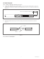
5.0 Install Splice
5.1 Applyatapemarkertosemi-coninsulationshieldoncablewhichdoesnotcontainsplice.Measure10"
(254mm)fromcenterofconnector(Figure17).
Tape Marker
Semi-con
10"
(254 mm)
Figure17
5.2 If using cold shrink adapter tube:Positionadaptertubeovertheconnector.Shrinkadapternearcenterof
connectorbypullingandunwindingtheloosecoreendinacounter-clockwisedirection(Figure18).
Cold shrink adapter tube
Figure18

78-8124-5934-1-E 11
5.3 Cleancablesusingstandardpractice:
a.Donotallowsolventorabrasivetocontactthecablesemi-conductiveinsulationshield.
b.Donotreducecableinsulationdiameterbelow1.04"(26,4mm)specifiedforthesplice.
c.Theinsulationsurfacemustberound,smoothandfreeofcuts/voids.Sandingmaybenecessary,finish
sandingshouldbedonewitha300gritorhigherelectricalgradeabrasive.
d.Makecertainthatthecableinsulationissmooth,cleananddrybeforecontinuing.
5.4 Applyredcompoundoncableinsulations,makingcertaintofillinedgeofcablesemi-con.Do not use
silicone grease(Figure19).
Apply Red
Compound
Apply Red
Compound
Fill semi-con step Fill semi-con step
Figure19
5.5 Positionthesplicebodyoverconnectorarea,aligningendofthesplicebody(notthecore)atthecenter
ofthetapemarker.Slowlystarttoremovethesplicecorebypullingandunwindingtheloosecoreend
counterclockwise,allowingonly¼"(6mm)ofthesplicetoshrinkontothetapemarker.Carefullyslidethe
splicebodyoffthetapemarkerbypullingandtwistinguntiltheentiretapemarkerisexposed.Continue
removingthecoretocompletethesplicebodyinstallation(Figure20).
Note: Thesplicebodyendsmustoverlapontothesemi-conofeachcablebyatleast1/2"(13mm).
Note: Donotpushthesplicebodytowardthetapemarkerasthismaycausetheendtorollunder.Iftheend
doesrollunder,DONOTusesharp-edgedtoolstopullitoutasthiscouldcutanddamagethesplice.
Unwind Counter-clockwise
Align splice body with tape marker
Figure20

12 78-8124-5934-1-E
6.0 Connect Shield Sleeve
6.1 Centertheexpandedshieldsleeveoversplicebody.Hand-tightensleevefromsplicecenteroutwardin
bothdirections(Figure21).
Shield Sleeve
Hand-tighten sleeve from splice center outward
Figure21
6.2 For Tape Shielded and LC Shielded Cables:
6.2.1 Securesleevetocablemetallicshieldnexttoeachcablejacketusingtwowrapsofvinyltape
(Figure22).
Cable Jacket End
Vinyl Tape Shield Sleeve
Figure22
6.2.2 Bendendsofsleevebackovervinyltapeandsecurewithconstantforcespringsat11/2"(38mm)
and21/2"(64mm)fromjacketend.Trimoffexcesssleeve1/2"(13mm)fromsprings,ifnecessary
(Figure23).
Constant Force Springs
Folded over shield sleeve
Trim end of sleeve if necessary
1 1/2"
(38 mm)
2 1/2"
(64 mm)
Figure23

78-8124-5934-1-E 13
6.2.3 Wraptwolayersofstretchedvinyltapeoversprings(Figure24).
Vinyl Tape
Figure24
6.3 For Wire Shielded Cable:
6.3.1 Carefullyremovevinyltapefromdrainwires.Securesleevetocablesemi-conductinglayernexttoeach
cablejacketusingtwowrapsofvinyltape(Figure25).
Vinyl Tape
Drain Wires
Figure25
6.3.2 Bendendsofsleevebackovervinyltape.Positiondrainwiresovertheshieldsleeveandsecurewith
constantforcespringsat11/2"(38mm)and21/2"(64mm)fromjacketend.Trimoffexcesssleeve
1/2"(13mm)fromsprings,ifnecessary(Figure26).
Constant Force Springs
Drain wires over shield sleeve
Trim end of sleeve if necessary
1 1/2"
(38 mm)
2 1/2"
(64 mm)
Figure26

14 78-8124-5934-1-E
6.3.3 Wraptwolayersofstretchedvinyltapeoversprings(Figure27).
Vinyl Tape
Figure27
6.4 For UniShield
®
Cable:
6.4.1 Carefullyremovevinyltapefromdrainwires.Securesleevetocablesemi-conjacketnexttobent-back
shielddrainwiresusingtwowrapsofvinyltape(Figure28).
Vinyl Tape
Drain Wires
Figure28
6.4.2 Bendendsofsleevebackovervinyltape.Carefullypositiondrainwiresovertheshieldsleeve.Secure
withconstantforcesprings11/2"(38mm)and21/2"(64mm)ontodrainwires.Trimoffexcesssleeve
1/2"(13mm)fromsprings,ifnecessary(Figure29).
Constant Force Springs
Drain wires over shield sleeve
Trim end of sleeve if necessary
1 1/2"
(38 mm)
2 1/2"
(64 mm)
Figure29

78-8124-5934-1-E 15
6.4.3 Wraptwolayersofstretchedvinyltapeoversprings(Figure30).
Vinyl Tape
Figure30
6.5 For CN and JCN Cable:
6.5.1 Connectshieldsleevetometallic(LC,etc.)shieldfirst.Removevinyltapefromneutralwiresandroute
neutralwiresupwardnexttoendofcablejacket(orCNbinder)(Figure31).
Neutral Wires
Figure31
6.5.2 Securesleevetocablesemi-connexttoneutralwiresusingtwowrapsofvinyltape.Covertheendofthe
splicebody(asshownbelow)withtwohalf-lappedlayersofrubberorvinyltape(Figure32).
Neutral Wires Shield Sleeve (twisted)
Vinyl Tape
Rubber or Vinyl Tape
Figure32

16 78-8124-5934-1-E
6.5.3 Placea3-4"pieceofcablejacketovertherubberorvinyltapeandcablesemi-conasshownbelow.
Securewithvinyltape(Figure33).
Cable Jacket Piece
Figure33
6.5.4 Keepingtheconnectorascloseaspossibletothecable,connectshieldsleeveandneutralstogether,
usingasuitablecompressionconnector.(“INLINE,”“C,”or“H”type).Crimpconnectorfollowingthe
connectormanufacturer’srecommendation.Trimexcessneutralwiresandsleeveextendingbeyondthe
connector(Figure34).
Compression connector
Figure34
6.5.5 Foldconnectorovershieldsleeve,ensuringthattheconnectorisoverthecablejacketpiece,andsecure
withvinyltape(Figure35).
Vinyl Tape
Figure35

78-8124-5934-1-E 17
7.0 Grounding (Optional)
Note: Usetheseinstructionsifcircuitgroundingisrequiredatthislocation.
7.1 Onmetallicshielded(non-neutral)cable,wrapthegroundstraparoundtheshieldsleeve(betweenthecable
jacketandconstantforcespring)withthetailstowardsthecablejacket(Figure36).
Ground Strap
Figure36
7.2 Securegroundstraptotheshieldsleeveusingaconstantforcespring(Figure37).
Constant Force Spring
Figure37
7.3 Wraptwolayersofstretchedvinyltapeoverspring(Figure38).
Vinyl Tape
Figure38

18 78-8124-5934-1-E
7.4 Placeonemasticsealingstriponthecablejacketunderthesolderblocksofthegroundstrap(Figure39).
Solder Block
Mastic Strip
Figure39
7.5 Placeotherstripoverthesolderblocks.Pressthemasticstripsaroundthesolderblockandtothecablejacket.
Iftailsoverlapatthesolderblocks,placeapieceofmasticbetweenthem(Figure40).
Second Mastic Strip
Figure40
8.0 Install Jacket
Note: Jacketingisnotoptional.
8.1 Applyonerollofslightlystretchedrubbermastictapearoundeachjacketend(tackysidetowardcable).Stretch
andtearofftheendoftherubbermasticasshownbelow.Ifgroundstrapwasapplied,tapeovermasticsealing
strips.ForCNcable,covermasticsealnexttobinder(Figure41).
Stretch and tear off last 1–2"
(25–50 mm) of rubber mastic
Rubber Mastic Rubber Mastic
Figure41

78-8124-5934-1-E 19
8.2 Begintoinstallthecoldshrinktubebycompletelycoveringtherubbermastic,andslowlypullingand
unwindingtheinnercorecounterclockwisetowardthesplicebody.Theoutercoreshouldremainrelatively
stationarywhileunwindingtheinnercore.Iftheoutercorebeginstomovetowardsthefirstmasticseal,gently
pulltheoutercoreandjacketingtubetowardsthesecondmasticsealandcontinueunwindingtheinnercore
(Figure42).
Unwind Counter-clockwise
Figure42
8.3 Continuetoinstallthecoldshrinktubeovertherubbermasticontheothercablebyslowlypullingand
unwindingtheoutercorecounterclockwise.Thisportionofthecoldshrinktubeinstallsdifferentlythantypical
coldshrinkproductsinthatasthetubeshrinks,theendrollsunder.Thetubemayneedaslightpushtogetover
thesecondmasticseal(Figure43).
Unwind Counter-clockwise
Figure43
Note: Inapplicationswherethespliceisregularlyexposedtohighlevelsofultra-violetradiation
(i.e.directsunlight),wraptwohalf-lappedlayersofScotch
®
Super33+
™
VinylElectricalTapeorScotch
®
VinylElectricalTapeSuper88overthere-jacketingtubes.
Note: Connectoptionalgrounding.

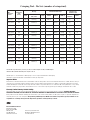
*Y45 and Y46 accept all Y35 dies (“U Series”). For Y45, use PT6515 adapter. For Y46, use PUADP adapter.
**Anderson VC6-3, VC6-FT and Burndy Y1000 require no die set.
3M and Super 33+ are trademarks of 3M Company. Scotch is a registered trademark of 3M Company.
UniShield is a registered trademark of General Cable Technologies Corporation.
Important Notice
All statements, technical information, and recommendations related to 3M’s products are based on information believed to be reliable, but the accuracy or
completeness is not guaranteed.
Before using this product, you must evaluate it and determine if it is suitable for your intended application.
You assume
all risks and liability associated with such use.
Any statements related to the product which are not contained in 3M’s current publications, or any contrary
statements contained on your purchase order shall have no force or effect unless expressly agreed upon, in writing, by an authorized officer of 3M.
Warranty; Limited Remedy; Limited Liability.
This product will be free from defects in material and manufacture for a period of one (1) year from the time of purchase.
3M MAKES NO OTHER
WARRANTIES INCLUDING, BUT NOT LIMITED TO, ANY IMPLIED WARRANTY OF MERCHANTABILITY OR FITNESS FOR A PARTICULAR PURPOSE.
If this product is defective within the warranty period stated above, your exclusive remedy shall be, at 3M’s option, to replace or repair the 3M product or
refund the purchase price of the 3M product.
Except where prohibited by law, 3M will not be liable for any indirect, special, incidental or con-
sequential loss or damage arising from this 3M product, regardless of the legal theory asserted.
3
Electrical Markets Division
6801 River Place Blvd.
Austin, TX 78726-9000
800-245-3573
Fax 800-245-0329
www.3M.com/electrical
Please Recycle. Printed in USA.
© 3M 2011. All Rights Reserved.
78-8124-5934-1-E
Crimping Tool - Die Sets (number of crimps/end)
™M3
rotcennoC
rebmuN
rotcudnoC
eziS
)limck(
ydnruB .proCstteB&samohT
.oCDerauqS
.viDnosrednA
A43Y
93Y,53Y
*64Y,*54Y
**0001Y 8MBT 21MBT 51MBT
**3-6CV
**TF-6CV
**C8CV
)uC(11001 053 )2(R13A )2(TR13U — )3(deR — )3(H17 )2( —
)uC/lA(11002 053 — )2(TRA13U )1( — )3(H78 )3(H78 )2( —
)uC(11011 053 )3(R13A )3(TR13U — )4(deR — )4(H17 )3( —
)uC/lA(053-IC 053 — )2(TRA13U — — )2(H78 )2(H78 )3( —
)uC/lA(21002 004 — )4(TRA23U )1( — )4(H49 )4(H49 )2( )2(
)uC(41001 005 )2(R43A )2(TR43U — )
3(nworB — )3(H78 )2( —
)uC/lA(41002 005 — )4(TRA43U )1( — )3(
H601 )4(H601 )2( )2(
)uC(41011 005 )4(R43A )3(TR43U — )4(nworB — )4(H78 )3( —
)uC/lA(005-IC 005 — )3(TRA43U — — — )3(H601 )3( —
)uC/lA(61002 006 — )4(TRA63U )1( — — )3(H511 )3( )3(
)uC(91001 057 — )3(TR93U — — — )3(H601 — —
)uC/lA(91002 057 — )4(TRA93U — — — )5(H521 )3( )3(
)uC(91011 057 — )5(TR93U — — — )4(H601 — —
)uC/lA(057-IC 057 — )3(TRA93S — — — )3(140H (3) —
-
 1
1
-
 2
2
-
 3
3
-
 4
4
-
 5
5
-
 6
6
-
 7
7
-
 8
8
-
 9
9
-
 10
10
-
 11
11
-
 12
12
-
 13
13
-
 14
14
-
 15
15
-
 16
16
-
 17
17
-
 18
18
-
 19
19
-
 20
20


3M Cold Shrink QS-III Splice 5515A-350-AL, UniShield®, Longitudinally Corrugated, 15 kV, 350 kcmil, 1/case Operating instructions
- Category
- Signal cables
- Type
- Operating instructions
- This manual is also suitable for
-
- Cold Shrink QS-III Splice 5515A-350-CU, UniShield®, Longitudinally Corrugated, 15 kV, 350 kcmil, 1/case
- Cold Shrink QS-III Splice 5515A-500-AL, UniShield®, Longitudinally Corrugated, 15 kV, 500 kcmil, 1/case
- Cold Shrink QS-III Splice Kit 5515A, Longitudinally Corrugated Shield, 15 kV, Standard, 1/case
- Cold Shrink QS-III Splice Kit 5515A-500-CU, 15 kV, Standard, 1/case
- Cold Shrink QS-III Splice Kit 5515A-750-AL, 15 kV, Standard, 1/case
- Cold Shrink QS-III Splice Kit 5515A-750-CU, 15 kV, Standard, 1/case
Ask a question and I''ll find the answer in the document
Finding information in a document is now easier with AI
Related papers
-
3M Cold Shrink QS-III Splice Kit 5516A-750-AL, 15 kV, Standard, 1/case Operating instructions
-
-
-
-
-
-
-
-
-
Other documents
-
PROFESSIONAL WIRELESS SYSTEMS S4448 User manual
-
Catamount TT-14-30-0-L Specification
-
Eaton EZ II Series Installation Instructions Manual
-
Hubbell Conventional Compression Splices Installation guide
-
Honeywell PK 81241Gold contact LS Installation guide
-
Ideal 46-411 Installation guide
-
 Off Road Only LiteSPOTZ 6 Light Under Chassis Kit Installation guide
-
WarmlyYours Snow Melt and Slab Heat Repair Kit Operating instructions
-
Eaton 600 A 15/25 kV class DT625 T-body Operating instructions
-
