Panasonic AJ-D950 User manual
- Category
- Cassette players
- Type
- User manual
This manual is also suitable for

Digital Video Cassette Recorder
AJ-
AJ-
Operating Instructions

IMPORTANT
“Unauthorized recording of copyrighted televi-
sion programs, video tapes and other materials
may infringe the right of copyright owners and
be contrary to copyright laws.
”
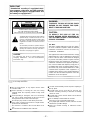
CAUTION
WARNING:
RISK OF ELECTRIC SHOCK
DO NOT OPEN
TO REDUCE THE RISK OF FIRE OR SHOCK
HAZARD, DO NOT EXPOSE THIS EQUIP-
MENT TO RAIN OR MOISTURE.
CAUTION: TO REDUCE THE RISK OF ELECTRIC SHOCK,
DO NOT REMOVE COVER (OR BACK).
NO USER-SERVICEABLE PARTS INSIDE.
REFER SERVICING TO QUALIFIED SERVICE PERSONNEL.
The lightning flash with arrowhead symbol, within an
equilateral triangle, is intended to alert the user to the
presence of uninsulated
“
dangerous voltage
”
within
the product
’
s enclosure that may be of sufficient
magnitude to constitute a risk of electric shock to
persons.
The exclamation point within an equilateral triangle is
intended to alert the user to the presence of important
operating and maintenance (servicing) instructions in
the literature accompanying the appliance.
CAUTION:
TO REDUCE THE RISK OF FIRE OR
SHOCK HAZARD, REFER MOUNTING OF
THE OPTIONAL BOARD TO AUTHORIZED
SERVICE PERSONNEL.
FCC Note:
This device complies with Part 15 of the FCC Rules.
To assure continued compliance follow the attached
installation instructions and do not make any
unauthorized modifications.
CAUTION:
To reduce the risk of fire or shock hazard and
annoying interference, use the recommended
accessories only.
This equipment has been tested and found to comply
with the limits for a Class A digital device, pursuant to
Part 15 of the FCC Rules. These limits are designed
to provide reasonable protection against harmful
interference when the equipment is operated in a
commercial environment. This equipment generates,
uses, and can radiate radio frequency energy and, if
not installed and used in accordance with the instruc-
tion manual, may cause harmful interference to radio
communications. Operation of this equipment in a
residential area is likely to cause harmful interference
in which case the user will be required to correct the
interference at his own expense.
is the safety information.
Do not insert fingers or any objects into the video
cassette holder.
Avoid operating or leaving the unit near strong
magnetic fields. Be especially careful of large audio
speakers.
Avoid operating or storing the unit in an excessively
hot, cold, or damp environment as this may result in
damage both to the recorder and to the tape.
Do not spray any cleaner or wax directly on the unit.
If the unit is not going to be used for a length of time,
protect it from dirt and dust.
Do not leave a cassette in the recorder when not in
use.
Do not block the ventilation slots of the unit.
Use this unit horizontally and do not place anything on
the top panel.
Cassette tape can be used only for one-side, one
direction recording. Two-way or two-track recordings
cannot be made.
Cassette tape can be used for either Color or Black &
White recording.
Do not attempt to disassemble the recorder.
There are no user serviceable parts inside.
If any liquid spills inside the recorder, have the recorder
examined for possible damage.
Refer any needed servicing to authorized service
personnel.
-2
-

Contents
General and Features
Controls and their functions
Front panel
Front panel bottom section
Connector area
Connections
Connections when one unit is used
Connections when 2 units are used
Connections with editing controller
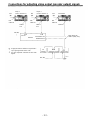
Connections for adjusting video output
(encoder output) signals
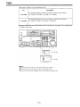
Tapes
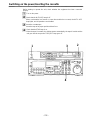
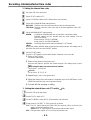
Switching on the power/inserting the cassette
STOP/STAND BY mode
Recording
Playback
Jog/shuttle
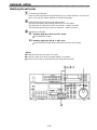
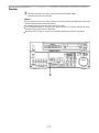
Manual editing
Preroll
Automatic editing
Switch settings and adjustments
Selecting the editing mode
Entering the edit points
Checking the edit points
Modifying the edit points
Preview
Executing automatic editing
Review
Split editing
Audio split editing
4
6
7
14
16
19
20
21
22
23
24
25
26
27
28
29
30
31
32
33
34
35
36
37
38
39
40
41
Video output (encoder output)
signal adjustment
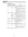
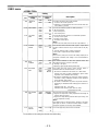
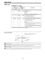
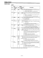
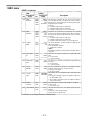
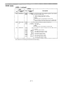
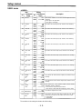
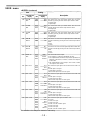
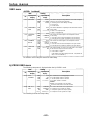
Setup (default settings)
Setup menus
System menu
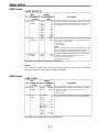
Basic menu
Operation menu
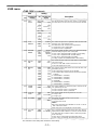
Interface menu
Edit menu
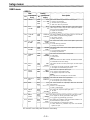
Tape protect menu
Time Code menu
Video menu
Audio menu
AJ-PD950 USER menu
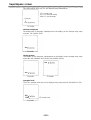
Time code/user bit
Recording internal/external time codes
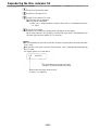
Reproducing the time code/user bit
Superimpose screen
Servo reference
Audio V Fade Function
Audio recording channel and monitor
output selection
Printed circuit board
Rack mounting
Head cleaning
Condensation
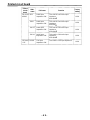
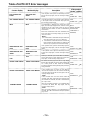
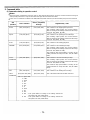
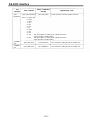
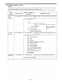
Error messages
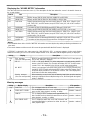
Table of AUTO OFF Error messages
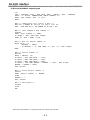
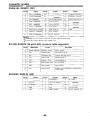
RS-232C interface
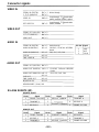
Connector signals
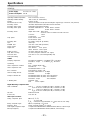
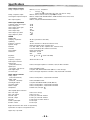
Specifications
Before operating this unit, check that all of its accessories are present and accounted for.
4
3
44
45
46
47
49
51
52
54
54
56
58
6
0
6
1
6
2
63
6
4
6
5
6
7
68
69
70
71
71
72
74
76
83
85
Power cord.... 1 pc
Option
AJ-MA75P Rack mounting adaptor
-3
-

General and Features
This multi-purpose studio digital video cassette recorder uses 1/4-inch compact video
cassette tapes, and it is designed to record, playback and edit both interlace signals (525i/
625i, 50 Mbps recording rate) and progressive signals (525p)* as well as record and play
back existing DVCPRO signals (25 Mbps). Its 525/625 switching function makes this a studio
video cassette recorder which can be used anywhere in the world. In addition, it corporates
digital compression technology so that the deterioration in picture quality and sound quality
resulting from dubbing is significantly minimized.
The compact, lightweight 4U size makes carrying easier, even when mounted in a 19-inch
rack. The settings for the unit’s setup can be performed interactively while viewing the screen
menus on the TV monitor, and editing functions include both assemble and insert editing.
The editing functions do not work when using this unit in DVCPRO (25 Mbps) mode.
Features
Compact size and light weight
This is a 4U-size digital VTR. It can be mounted in a 19-inch rack with ease using the
optional rack-mounting adaptors (AJ-MA75P).
Up to 92 minutes of recording
Two sizes of cassette tapes can be used with this unit: M cassette (max. 33 minutes) and L
cassettes (max. 92 minutes). The width of the tapes measures 1/4 inch to achieve a compact
design.
Superior Picture quality
Superior picture quality is delivered in the component signal and the 4:2:0p progressive
signal* recording mode.
Switchable 525i/625i/525p*
The video input signal switch (settings: 525i/625i/525p*) can be set to accommodate the
recording and playback of each type of signal.
SDI interface
This product’s standard features include 4:2:2/4:2:0p* serial digital interface.
Playback compatibility with DVCPRO
This product is also capable of recording in the existing DVCPRO format and playing back
tapes which have been recorded using this format.
Digital slow motion/dial jog
With Panasonic’s unique digital slow motion technology, slow motion playback images are
clear at the following speeds: -0.43/-0.3/-0.2/-0.1/-0.03/+0.03/+0.1/+0.2/+0.3/+0.5/+0.75
<Note>
Some noise may occur when the slow motion speed is changed.
Dial shuttle
Shuttle operations enable the tape to be played back with color images at a speed of up to
32 times the forward and reverse direction.
*Applies only to
AJ-PD950.
Time codes
This unit comes with a built-in time code generator (TCG)/time code reader (TCR). In
addition to the internal time code, an external code input or input signal VITC can be
recorded on this VTR as the LTC time code.
-4-

Features
(continued)
Multifunctional interface
Serial digital input/output
The component serial interface, a standard feature, allows for interfacing with progressive
signals* and component signals in serial digital (SMPTE259M-C, 272M, 294M*).
Analog video input/output
Analog component input/output signals (Y, P
B
, P
R
) as well as composite input/output signals
are standard feature.
AES/EBU audio input/output
Digital audio input/output connectors are featured.
SDTI input/output
9-pin (RS-422A)/(RS-232C) remote
In addition to the standard 9-pin serial remote (RS-422A), RS-232C and 25-pin parallel
remote connectors are also featured.
The RS-422A connector enables another VTR to be operated in parallel with the unit if a
looping connection is used for the two units.
4-channel high-sound-quality digital audio
The 4-channel PCM audio allows for not only independent editing and mixing on all four
channels. One channel is provided for the analog CUE track.
Applies only to
AJ-PD950.
Menu-driven setup
The setup settings, which are conducted prior to operating the unit are performed while
viewing the setup menus either on the unit
’
s display or a TV monitor.
-5
-

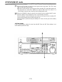
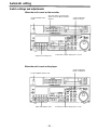
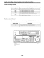
Controls and their functions
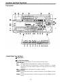
Front panel
<Front Panel Top Section>
POWER switch
TV system/format displays
These displays indicate the type of TV system selected and tape format.
<525/525P*/625>
525:
This lights when the 525 interlaced TV system has been selected.
525P*:
This lights when the 525 progressive TV system is selected or is currently
playing back. [The 525P setting is selected on setup menu No. 012 (SYSTEM
FORMAT).]
625:
This lights when a 625 interlaced TV system is selected.
<25Mbps/50Mbps>
25Mbps:
This indicates that the tape is recorded or played back in the 25Mbps DVCPRO
format.
50Mbps:
This indicates that the tape is recorded or played back in the 50Mbps DVCPRO
format.
-6-

Applies only to
AJ-PD950.
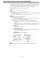
INPUT SELECT switches
These are used to select the video and audio input signals.
<Video>
Each time the VIDEO button is pressed, the input video signal selection is switched in the
order of Y/P
B
/P
R
, COMPOSITE, SDTI (V&A), SDI and then back to Y/P
B
/P
R
. When SDTI
(V&A) is selected, both video input and audio input are switched to SDTI.
<Audio>
Each time the AUDIO button is pressed, the input audio signal selection is switched in the
order of ANALOG, AES/EBU, USER SET, SDI and then back to ANALOG. USER SET is a
feature for independently selecting the input signals to record on PCM audio signal
channels 1 through 4, and is used together with the setup menu. However, when video
input is set to SDTI, audio input is also forcibly set to SDTI. For instance, if USER SET is
selected by INPUT SELECT and the channel selections are CH1=ANALOG on setup
menu No. 715, CH2=DIGlTAL on No. 716, CH2=AES on No. 719, CH3=DIGlTAL on No.
717, CH3=SIF on No. 720, and CH4=ANALOG on No. 718, then analog input signals are
recorded on PCM audio signal CH1 on the tape, AES/EBU digital signals on CH2, SDI
input digital signals on CH3, and analog input signals on CH4.
INPUT SELECT display
The characters corresponding to the selected input signal light up.
With the exception of analog audio signals, the display flashes to alert the user when the
selected input signal is not supplied.
<Video>
Y PB PR:
Analog component video signal
CMPST:
Analog composite video signal
SDTI (V&A):
Compressed data serial digital video/audio signal (optional)
SDI:
Serial digital video signal (SMPTE259M-C, 272M, 294M*)
(The entire display lights when signal generation using the internal signal generator has
been selected for setup menu No. 600 (INT SG).)
<Audio>
ANALOG:
Analog audio signal
AES/EBU:
Digital audio signal
USER SET:
Selection of the audio signal to record
SDI:
Serial digital audio signal
(The entire display lights when signal generation using the internal signal generator has
been selected for setup menu No. 700 (INT SG).)
Cassette insertion slot
EJECT button
When this is pressed, the tape is unloaded and several seconds later the cassette is
automatically ejected. When the counter display indicates “CTL”, the display is reset.
Channel condition lamps
One of these lamps lights in accordance with the error rate status. (Green
Amber
Red)
Green:
This lights when the error rates for the video and audio playback signals are both
acceptable.
Amber:
This lights when the error rate for the video or audio playback signals has
deteriorated.
Red:
The playback picture will remain normal even when this lamp lights.
This lights when the video or audio signals are subject to rectification or
interpolation.
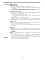
AUTO OFF lamp
This lights when trouble has arisen in the decks operation.
-7-

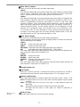
Controls and their functions
(continued)
<Front Panel Center Section>
PLAY button
Playback commences when this button is pressed.
Recording commences when the button is pressed together with the REC button; manual
editing commences when it is pressed together with the EDIT button during playback.
However, manual editing will not be initiated if the servo is not locked.
Pressing only the PLAY button during manual editing will cut out the editing and establish
the playback mode.
REC button
Recording commences when this button is pressed together with the PLAY button.
When it is pressed during playback, search*
1)
,
fast forward or rewind, EE mode images
and audio signals can be monitored for as long as it is kept depressed.
When it is pressed in the stop mode, EE mode images and sound can be monitored.
When the STOP button is pressed, the original picture and sound are restored.
STOP button
When this is pressed, the tape stops traveling, and if the TAPE/EE selector switch is at
TAPE, still pictures can be monitored.
The drum continues to rotate even in the stop mode, and the tape remains in close contact
with the drum.
If the stop mode continues for more than a certain period of time, the unit automatically
switches to the standby OFF mode in order to protect the tape.
The stop mode is established immediately after a cassette has been inserted into the unit.
FF button*
2)
The tape is fast forwarded when this is pressed.
REW button*
2)
The tape is rewound when this is pressed.
EDIT button
For manual editing, press both this button and the PLAY button together during playback.
When the button is pressed in the stop mode, the input mode signals selected by the
ASSEMBLE or INSERT button can be monitored in the EE mode.
The original picture and sound are restored when the STOP button is pressed.
When the button is pressed during playback, search*
1)
,
fast forward or rewind, the input
signals of the mode selected by the ASSEMBLE or INSERT button can be monitored in
the EE mode for as long as the button is held down.
SERVO lamp
This lights when the drum servo and capstan servo have locked.
*
1)
No guarantees are given for the audio playback sound in the search mode.
*
2)
The FF/REW speed can be selected on the setup menu No. 102 (FF. REW MAX), and it is
set to the same speed.
-8-

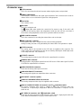
<Front Panel Center Section>
REC INHIBIT lamp
This lights when the REC INHIBIT switch in the front panel bottom section is at ON or
when the accidental erasure prevention mode has been set for the cassette.
In this state, neither recording nor editing is possible.
STAND BY button
When this is pressed, the same tension as in the regular stop mode is applied to the tape,
and while the head drum continues to rotate, the button’s lamp lights to indicate that the
standby ON mode is established.
In the standby OFF mode, the half-loading mode is established.
When this button is pressed in the stop mode, the standby OFF mode is established, the
half-loading mode is established. The lamp in the button now goes off. When the unit
remains in the stop mode for longer than a predetermined period, the standby OFF mode
is automatically established in order to protect the tape.
When this button or the STOP button is pressed in the standby OFF mode, the standby
ON mode is established.
When a button other than the STOP button is pressed, the mode corresponding to the
button pressed is established.
On-screen settings are available for the transfer time to the standby OFF mode.
PLAYER/RECORDER buttons
These buttons are operated when editing operations are conducted using the unit as the
recorder and a VTR equipped with an RS-422A serial interface remote control connector
(9 pins). Neither button functions when the unit is used on its own.
PLAYER button:
When this button is pressed, its lamp lights, and the player connected
to the unit can be operated by remote control. The unit’s editing and
tape transport buttons now control the player’s functions.
RECORDER button:
When this button is pressed, its lamp lights, and the editing and tape
transport buttons control the recorder’s (= the unit’s) functions.
Both lamps light, and the recorder functions as the master unit for Parallel Run operations
if the PLAYER or RECORDER button is pressed while “ENA” has been selected for setup
menu No. 200 (PARA RUN). [However, external control can no longer be exercised from
the REMOTE connector (9-pin) when this setting has been made.]
TC/CTL switch
By pressing this switch, what appears on the counter display is changed between TC and
CTL.
When TC is selected, either the TC or UB value is displayed depending on the position
selected by the TC/UB switch.
TC/UB switch
This selector switch determines whether the value of TC or UB appears on the counter
display when the TC/CTL switch has been set to TC.
INT/EXT switch
INT:
For using the built-in time code generator.
EXT:
For using the time external code which is input from the time code input connector or
the video signal VITC. The selection is set at the setup menu No. 505 (EXT TC SEL).
TAPE/EE switch
<In the stop mode>
TAPE:
For outputting the signals played back from the tape.
EE:
For outputting the input signals selected by the INPUT SELECT switch.
<ln the editing*/recording mode>
TAPE:
For outputting the simultaneous playback signals.
EE:
For outputting the input signals selected by the INPUT SELECT switch.
* The SETUP menu No. 310 (CONFI EDIT) setting is required.
-9-

Controls and their functions (continued)
<Front Panel Center Section>
REMOTE/LOCAL switch
This switch is set when the unit is to be controlled from an external source using the
REMOTE connector, RS-232C connector or parallel connector.
REMOTE:
Set to this position when controlling the unit by a device connected using the
9-pin REMOTE connector or RS-232CY parallel connector.
LOCAL:
Set to this position when controlling the unit using the controls on its own
operation panel.
REMOTE lamp
This lights when the REMOTE/LOCAL switch has been set to the REMOTE position.
Search button
This button is pressed to establish the search mode.
When the search dial is set to the shuttle mode and turned to a particular position, and this
button is pressed, playback commences at the speed set by the search dial.
JOG/SHTL/SLOW lamps
These indicate the present status of the search dial and SHTL/SLOW switch.
JOG:
This lights when the unit is in the JOG mode.
SHTL:
This lights when the unit is in the SHTL mode.
SLOW:
This lights when the unit is in the VAR (variable) mode.
SHTL/SLOW switch
This selector switch is set when the search dial is used for SHTL or SLOW applications.
REV/STILL/FWD lamps
One of these lamps lights depending on the operation of the search dial.
REV:
This lights when the dial is turned counterclockwise and the tape travels in the
REV direction provided that the lamp in the search button has lighted.
STILL:
This lights in the JOG mode while the dial is kept stationary, and the tape stops
traveling provided that the lamp in the search button has lighted.
It lights in the SHTL mode provided that the dial is at the STILL position.
FWD:
This lights when the dial is turned clockwise, and the tape travels in the FWD
direction provided that the lamp in the search button has lighted.
Search dial
This is used to search for the edit points.
Each time it is pressed, the mode is alternately set to shuttle or jog, and one of the JOG,
SHTL and SLOW lamps lights. When the power has been turned on, the dial will not
function until it has first returned to the STILL position.
Shuttle mode:
When the dial is turned and stopped at a particular position while the
SHTL/SLOW switch is at SHTL, the tape can be played back at the speed
corresponding to the dial’s rotary angle position. A still picture appears at
the dial’s center position.
When the dial is turned all the way counterclockwise with the SHTL/SLOW
switch at SLOW, the tape speed is set to -4.1x normal speed, when it is
set to the center position, a still picture is produced, and when it is turned
all the way clockwise, the tape speed is set to +4.1x normal speed. The
speed for SLOW can be set using setup menu No. 300 (VAR RANGE).
Jog mode:
The dial clickstops are cleared, and the tape is played back at the speed
(-0.43x to +1x normal speed) corresponding to the speed at which the dial
is turned.
-10-

<Front Panel Center Section>
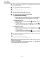
PREROLL button
This is used for feeding and cueing the tape for manual editing.
When it is pressed, the tape travels to the preroll point where it stops.
The preroll time can be set on the setup menu No. 000 (P-ROLL TIME).
When this button is pressed together with the IN or OUT button, the tape can be cued to
the IN or OUT point entered.
When the AUTO ENTRY on the setup menu No. 313 is set to “ENA”, IN point has been
entered at the point where the PREROLL button is pressed even if the IN point has not
been entered.
AUTO EDIT button
Automatic editing is executed when this is pressed after an edit point has been entered.
When the AUTO EDIT button is pressed though the IN point has not been entered,
automatic editing is executed using the point at which the button was pressed as the IN
point.
PREVIEW/REVIEW buttons
PREVIEW:
When this is pressed after an edit point has been entered, the tape travels,
editing is not performed, and the preview can be activated on the screen
connected to the recorder.
If it is pressed when the IN point has not been entered, the point at which the
button was pressed is entered as the IN point, and preview is executed
accordingly.
REVIEW:
If this is pressed after a block has been edited, the now edited block can be
played back and monitored on the screen connected to the recorder.
IN (A IN)/SET/OUT (A OUT) buttons
When IN (A IN) or OUT (A OUT) button is pressed together with the SET button, the IN (A
IN) or OUT (A OUT) point is entered.
A IN and A OUT are used during audio split editing to enter an audio IN or OUT point that
differs from the video In or OUT point.
While an IN (A IN) or OUT (A OUT) point is selected, the IN (A IN) or OUT (A OUT) button
corresponding to the point entered lights. When this button is pressed after a point has
been entered, the IN (A IN) /OUT (A OUT) point value appears on the counter display.
When the IN (A IN) or OUT (A OUT) button is pressed together with the RESET button, the
IN (A IN) or OUT (A OUT) point is cleared.
TRIM buttons
These buttons are used to trim IN or OUT point finely.
When the
“+”
or
“-”
button is pressed while the IN or OUT button is held down, the entered
edit point can be trimmed in 1-frame increments. When the “+” button is pressed, the tape
is advanced by one frame; when the “-” button is pressed, it is rewound by one frame.
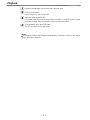
ASSEMBLE button
This is pressed for assemble editing.
The button is self-illuminating, and it is set ON (lamp lights) when it is pressed once and
OFF (lamp goes off) when it is pressed again.
INSERT buttons
Press one of these five buttons to select the input signals to be edited during insert editing.
The buttons are self-illuminating, and they are set ON (lamp lights) when they are pressed
once and OFF (lamp goes off) when they are pressed again.
Counter display
This displays the TC and CTL count values, on-screen information and other messages.
-11-

Controls and their functions
(continued)
<Front Panel Center Section>
Time code buttons
These are used to set the TC or UB value.
SHIFT:
When setting the TC or UB value, first press this button to stop the data running.
Change the digit now flashing on the display.
Each time the button is pressed, the flashing moves to the right by one digit, and
when it reaches the right-most digit, it returns to the left-most digit.
When it is kept depressed, the flashing moves consecutively.
ADJ:
This is used to change the numeral of the digit now flashing on the display.
When the button is pressed once, the number is incremented by 1, and when it is
kept depressed, the number is incremented consecutively.
START:
This enters the data which has been changed by the SHIFT and ADJ buttons.
Also, Pressing this button when the TC or UB value are not set enables the TCG
or UBG setting values to be confirmed.
RESET:
When this button is pressed in the CTL mode, the display is reset to
“00:00:00:00”. In the CTL mode, the entered edit points are cleared.
In the TC/UB mode, the generator is reset when the button is pressed together
with the SHIFT button.
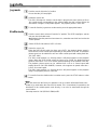
Warning lamp
This lights to warn the operator of a particular item.
Cassette insertion display lamp
This lights when a cassette has been inserted into the unit.
DVCPRO format (25Mbps) cassette playback display lamp
This lights when a cassette recorded in the DVCPRO format (25 Mbps) is being played
back.
SCH lamp
This lights when the SCH of the external sync signal is within a specific range.
CF lamp
This lights when the color framing is locked.
Level meters
These indicate the respective levels of the PCM audio signals (CH1/CH2/CH3/CH4), CUE
track signal or the video signal*. The audio signal indicates the input signal levels during
recording and E-E selection, and the output signal levels during playback.
For video signal, the meters indicate the input signal levels only.
*CUE track signal or video signal is to be selected on setup menu No. 005 (METER
SELECT).
Audio input/output level controls
These controls are used to adjust the recording and playback levels of the PCM audio
signals (CH1/CH2/CH3/CH4) and the CUE track signal. The upper controls are for
adjusting the recording levels. The lower controls are for adjusting the playback levels.
Each control is a “pull for variable” control, meaning that the level can be adjusted only
when the control has been pulled up. The signal levels are set to the unity value (preset
value) when the controls have been pushed down.
Headphones jack
The sound being recorded, played back or edited can be monitored on stereo
headphones when they are connected to this jack.
-12-

<Front Panel Center Section>
Volume control
This is used to adjust the headphones volume and the monitor output volume.
Whether the headphones output and monitor output volumes are to be linked or kept
separate can be set on the setup menu No. 713 (MONI OUT). (Note that the headphones
output volume is normally linked.)
When the volumes are kept separate, the monitor output is set to the unity value (preset
value).
MONITOR SELECT switches
These are used to select the audio signals output to the monitor L/R channels.
Each time the “L” button is pressed, the signals output to the monitor L channel are
selected in turn in the following order: CH1, CH2, CH3, CH4, CUE and back to CH1.
[However, this switching is disabled when CH1+2 or CH3+4 has been selected for setup
menu No. 729 (MONITOR MIX L).]
Each time the “R” button is pressed, the signals output to the monitor R channel are
selected in turn in the following order: CH1, CH2, CH3, CH4, CUE and back to CH1.
[However, this switching is disabled when CH1+2 or CH3+4 has been selected for setup
menu No. 730 (MONITOR MIX R).]
The L or R lamp on the level meter display lights to indicate which signal is now being
selected. (When the unit is set to “AUTO” in No. 721 (MONI CH SEL) on the setup menu,
then the display will change according to the monitor output.)
METER (FULL/FINE) selector switch
This is used to change the scale display (graduations) of the audio level meters.
FULL mode:
Standard scale (from -
to 0 dB)
FINE mode:
The scale changes every 0.5 dB
-13-

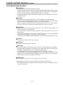
Controls and their functions
(continued)
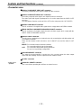
<Front Panel Bottom Section>
VIDEO IN LEVEL control and switch
These are used to adjust the video input level.
PRESET:
When the switch is set to “PRESET”, the video input level is set to the unity
value (0 dB).
MANUAL:
When the switch is set to “MANUAL”, the video input level can be adjusted
using this control.
VIDEO OUT LEVEL control and switch
When setup menu No. 00 (ENCODER SEL) is set to “LOCAL”, the video output level can
be adjusted.
When the switch is set to “PRESET”, the video output level is set to the unity value (0 dB).
When the switch is set to “MANUAL”, the video output level can be adjusted using this control.
CHROMA LEVEL control and switch
When setup menu No. 00 (ENCODER SEL) is set to “LOCAL”, the chroma level can be
adjusted.
When the switch is set to “PRESET”, the chroma level is set to the unity value (0 dB).
When the switch is set to “MANUAL”, the chroma level can be adjusted using this control.
SETUP control and switch
When setup menu No. 00 (ENCODER SEL) is set to “LOCAL”, the setup level can be
adjusted.
When the switch is set to “PRESET”, the setup level is set to the unity value (0 IRE).
When the switch is set to “MANUAL”, the setup level can be adjusted using this control.
HUE control and switch
When setup menu No. 00 (ENCODER SEL) is set to “LOCAL”, the hue can be adjusted.
When the switch is set to “PRESET”, the hue is the unity value (0°).
When the switch is set to “MANUAL”, the hue can be adjusted using this control.
CF switch
This selects whether the playback framing is to be locked in 4-field or 8-field increments or
2-field increments.
* Applies only to
AJ-PD950
4F/8F:
525 mode: The framing is locked in 4-field increments.
625 mode: The framing is locked in 4- or 8-field increments. The framing can be
selected in either 4- or 8-field increments using setup menu No. 108
(CAP. LOCK).
2F:
The framing is locked in 2-field increments.
TC generator switch
REGEN:
When the REGEN/PRESET switch is at REGEN, the internal time code
generator is synchronized with the time code which the time code reader
read from the tape. Whether to set TC or UB to REGEN can be selected at
the setup menu No. 503 (TCG REGEN).
PRESET:
When the REGEN/PRESET switch is at PRESET, presetting is enabled by
the controls on the operation panel or by remote control.
REC RUN:
The time code runs only during recording when the RUN MODE switch has
been set to REC. The time code runs constantly when the REGEN/PRESET
switch is set to REGEN.
FREE RUN:
The time code runs regardless of the operation mode as long as the power is
being supplied when the RUN MODE switch has been set to FREE.
-14-

<Front Panel Bottom Section>
REC INHIBIT switch
This is used to inhibit or allow recordings on the video cassette tape.
ON:
Recording on the tape is inhibited. At this setting, the REC INHIBIT lamp in the front
panel lights.
OFF:
Recording on the tape is allowed provided that the accidental erasure prevention
tab on the video cassette tape enables recording to be conducted.
TV SYSTEM selector switch
This selects the type of television system. The setting of this switch takes effect when the
power is turned off and then turned back on again.
525:
525 interlaced/59.94 Hz television selection.
The 525 progressive system* is selected using setup menu No. 012 (SYSTEM
FORMAT).
625:
625 interlaced/50 Hz television system selection.
During recording, choose a signal input that corresponds to the 525i/625i/525p* selection.
During playback, choose a video cassette tape that corresponds to the 525i/625i/525p*
selection.
MENU button
When this is pressed, the setup menu appears on the TV monitor using VIDEO OUT 3
connector, and the setup menu No. appears on the display.
When it is pressed again, the menu setting mode is exited and the original operating mode
is restored.
SET button
When this is pressed, the data which has been set on the setup menu is entered. After
data entry, the setup menu setting mode is exited and the original operating mode is
restored.
* Applies only to
AJ-PD950.
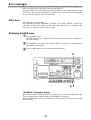
DIAG button
When this is pressed, VTR information is displayed. When it is pressed again, the original
display is restored.
There are two types of VTR information: “HOURS METER” information and “WARNING”
information. Switching between these types is enabled by pressing the search button.
Indicated on the “HOURS METER” screen are the power-on time, drum rotation time, tape
travel time, loading count and power ON/OFF time, etc.
Indicated on the “WARNING” screen are the warnings.
-15-

Controls and their functions
Connector area
-16
-

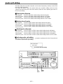
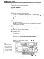
<Connector area>
AC IN connector
This is for connecting the unit to the power outlet using the power cord provided.
SIGNAL GND terminal
This terminal is connected to the signal ground terminal of the connected unit in order to
reduce noise. It is not connected to ground for safety purposes.
Fuse holder
This contains a fuse.
Fan motor
This is for cooling the unit.
The
lamp lights when trouble has caused the fan motor to stop. If the unit is still
operated in the warning status, the temperature inside the deck will rise, and when it
exceeds the safety temperature, all the unit’s operations will be shut down.
TIME CODE IN connector
This is the connector for recording the external time code on the tape.
TIME CODE OUT connector
The playback time code is output from this connector during playback.
During recording, the time code generated by the internal time code generator is output.
CUE IN connector
The analog signal to be recorded on the CUE track is supplied to this connector. The
audio signals from a microphone can also be recorded by selecting the -60dB input mode
on the setup menu No. 705 (CUE IN LV).
CUE OUT connector
The analog signal recorded on the CUE track is output from this connector.
MONITOR OUT connector
During playback, the playback signals from the CUE track or PCM audio signal CH1/CH2/
CH3/CH4 are output from this connector.
ANALOG AUDIO IN connectors
These are the analog audio input connectors.
ANALOG AUDIO OUT connectors
The analog audio signals are output from these connectors.
SDTI IN/OUT connector (option)
ANALOG COMPONENT VIDEO IN connector
The analog component video signal is supplied to this connector.
ANALOG COMPOSITE VIDEO IN connectors and 75 termination switch
The analog composite video signal is supplied to these two connectors which are
connected in a loop-through configuration. When the termination is required, set the
switch to ON.
REF VIDEO IN connectors and 75 termination switch
These are the input connectors for the reference video signals. Supply signals with color
burst. When the termination is required, set the switch to ON.
-17-

Controls and their functions
(continued)
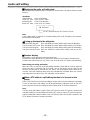
<Connector area>
ANALOG COMPONENT VIDEO OUT connector
The analog component video signal is output from this connector.
ANALOG COMPOSITE VIDEO OUT connectors
The analog composite video signals are output from these connectors.
The video signal with signals superimposed on it can be output from the VIDEO OUT3
connector.
The superimpose function can be set ON or OFF on the setup menu No. 007 (SUPER).
DIGITAL AUDIO IN/OUT connector
This I/O connector is for digital audio signals which comply with the AES/EBU standard.
SERIAL DIGITAL COMPONENT AUDIO/VIDEO IN/OUT connector
This I/O connector is for digital component audio and video signals which comply with the
SMPTE 259M-C/272M/294M* standard.
Remote control connectors
The unit can be controlled from an external source by connecting the unit with another unit
or an external controller.
There are two remote control connectors, one for IN/OUT uses and the other for OUT
uses.
IN/OUT:
For connection with an external controller.
For connection with deck-to-deck operation.
OUT
For connection with parallel running operations.
For use in a loop-through configuration.
ENCODER REMOTE connector
The external encoder/controller is hooked up to this connector when the video output
signal and other settings are to be adjusted from an external source.
RS-232C connector
*
Applies only to
AJ-PD950.
PARALLEL REMOTE connector
This is used when operating the unit from an external source.
-18-

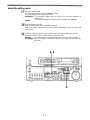
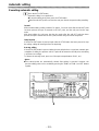
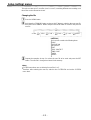
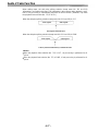
Connections when one unit is used
Set the CONTROL switch on the front panel to LOCAL.
Audio monitor output connectors
Analog video input connectors
Reference input connectors
Digital audio/video
input connector
Digital audio
output
Digital audio/video output
Analog audio input connectors
connector
Digital audio
input connector
Active through output
connector
Analog audio output connectors
Video monitor output connectors
-19-

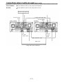
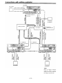
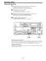
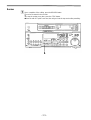
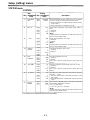
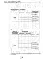
Connections when 2 units are used
(deck to deck)
Source machine:
Set the CONTROL switch on the front panel to REMOTE.
Recorder:
Set the CONTROL switch on the front panel to LOCAL.
Reference Signal generator
To audio monitor
device
Source machine
OFF
Remote control signal (9P)
To audio monitor
Recorder
device
ON
To video
monitor device
Digital video/audio signal
Digital audio
Analog video signal (component)
To video
monitor
device
-20-
Page is loading ...
Page is loading ...
Page is loading ...
Page is loading ...
Page is loading ...
Page is loading ...
Page is loading ...
Page is loading ...
Page is loading ...
Page is loading ...
Page is loading ...
Page is loading ...
Page is loading ...
Page is loading ...
Page is loading ...
Page is loading ...
Page is loading ...
Page is loading ...
Page is loading ...
Page is loading ...
Page is loading ...
Page is loading ...
Page is loading ...
Page is loading ...
Page is loading ...
Page is loading ...
Page is loading ...
Page is loading ...
Page is loading ...
Page is loading ...
Page is loading ...
Page is loading ...
Page is loading ...
Page is loading ...
Page is loading ...
Page is loading ...
Page is loading ...
Page is loading ...
Page is loading ...
Page is loading ...
Page is loading ...
Page is loading ...
Page is loading ...
Page is loading ...
Page is loading ...
Page is loading ...
Page is loading ...
Page is loading ...
Page is loading ...
Page is loading ...
Page is loading ...
Page is loading ...
Page is loading ...
Page is loading ...
Page is loading ...
Page is loading ...
Page is loading ...
Page is loading ...
Page is loading ...
Page is loading ...
Page is loading ...
Page is loading ...
Page is loading ...
Page is loading ...
Page is loading ...
Page is loading ...
Page is loading ...
-
 1
1
-
 2
2
-
 3
3
-
 4
4
-
 5
5
-
 6
6
-
 7
7
-
 8
8
-
 9
9
-
 10
10
-
 11
11
-
 12
12
-
 13
13
-
 14
14
-
 15
15
-
 16
16
-
 17
17
-
 18
18
-
 19
19
-
 20
20
-
 21
21
-
 22
22
-
 23
23
-
 24
24
-
 25
25
-
 26
26
-
 27
27
-
 28
28
-
 29
29
-
 30
30
-
 31
31
-
 32
32
-
 33
33
-
 34
34
-
 35
35
-
 36
36
-
 37
37
-
 38
38
-
 39
39
-
 40
40
-
 41
41
-
 42
42
-
 43
43
-
 44
44
-
 45
45
-
 46
46
-
 47
47
-
 48
48
-
 49
49
-
 50
50
-
 51
51
-
 52
52
-
 53
53
-
 54
54
-
 55
55
-
 56
56
-
 57
57
-
 58
58
-
 59
59
-
 60
60
-
 61
61
-
 62
62
-
 63
63
-
 64
64
-
 65
65
-
 66
66
-
 67
67
-
 68
68
-
 69
69
-
 70
70
-
 71
71
-
 72
72
-
 73
73
-
 74
74
-
 75
75
-
 76
76
-
 77
77
-
 78
78
-
 79
79
-
 80
80
-
 81
81
-
 82
82
-
 83
83
-
 84
84
-
 85
85
-
 86
86
-
 87
87


Panasonic AJ-D950 User manual
- Category
- Cassette players
- Type
- User manual
- This manual is also suitable for
Ask a question and I''ll find the answer in the document
Finding information in a document is now easier with AI
Related papers
-
Panasonic DVR AJ-D950 User manual
-
-
-
-
-
-
-
-
-
