
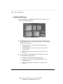
HB1004 10B -T HASE UB
USER GUIDE

. . . . . . . . . . . . . . . . . . . . . . . . . . . . . .
Writer: Weldon W. Rowan Project: Compaq HB1004 10Base-T Hub User Guide Comments:
File Name:sab_n1.DOC Last Saved On:7/2/98 3:20 PM
NOTICE
The information in this publication is subject to change without notice.
COMPAQ COMPUTER CORPORATION SHALL NOT BE LIABLE FOR TECHNICAL OR
EDITORIAL ERRORS OR OMISSIONS CONTAINED HEREIN, NOR FOR INCIDENTAL OR
CONSEQUENTIAL DAMAGES RESULTING FROM THE FURNISHING, PERFORMANCE, OR
USE OF THIS MATERIAL.
This publication contains information protected by copyright. No part of this publication may be
photocopied or reproduced in any form without prior written consent from Compaq Computer
Corporation.
The software described in this guide is furnished under a license agreement or non disclosure agreement.
The software may be used or copied only in accordance with the terms of the agreement.
Product names mentioned herein may be trademarks and/or registered trademarks of their respective
companies.
1998 Compaq Computer Corporation.
All rights reserved. Printed in the U.S.A.
Compaq
Registered United States Patent and Trademark Office.
Compaq HB1004 10Base-T Hub User Guide
First Edition (July 1998)
Part Number 358665-021

. . . . . . . . . . . . . . . . . . . . . . . . . . . . . .
v
Compaq HB1004 10Base-T Hub User Guide
Writer:
Chris Seiter
Project:
Contents
Comments:
File Name:
Sab_toc.doc
Last Saved On:
7/2/98 4:40 PM
Contents
Chapter 1
Overview
Features .......................................................................................................................1-1
Package Contents.........................................................................................................1-2
Hub Components.........................................................................................................1-3
RJ-45 Ports...........................................................................................................1-3
Serial COM Port...................................................................................................1-3
LED Indicators.....................................................................................................1-3
MDI/MDI-X Slide Switch....................................................................................1-5
Chapter 2
Installation
Mounting the Hub........................................................................................................2-1
Mounting the Hub on a Flat Surface............................................................................2-1
Mounting the Hub in a Rack........................................................................................2-2
Connecting the Hub System........................................................................................2-3
Making a Connection via an MDI-X Port............................................................2-3
Making a Connection via the MDI/MDI-X Port (Port 4).....................................2-4
Powering On the Hub..................................................................................................2-4
Diagnostic Tests ..........................................................................................................2-6
Verifying Hub and Port Status.....................................................................................2-7
Applications.................................................................................................................2-8
Chapter 3
Setup and Configuration
Preparing for Configuration Management...................................................................3-1
Out-of-Band Connection......................................................................................3-1
In-Band Connection .............................................................................................3-3
Starting the Configuration Program.............................................................................3-3

. . . . . . . . . . . . . . . . . . . . . . . . . . . . . .
vi
Writer:
Chris Seiter
Project:
Contents
Comments:
File Name:
Sab_toc.doc
Last Saved On:
7/2/98 4:40 PM
Compaq HB1004 System Configuration.....................................................................3-7
Displaying System Information..........................................................................3-10
Changing System Configuration ........................................................................3-11
Assigning Trap Managers...................................................................................3-12
Configuring Port Parameters..............................................................................3-13
Network Performance................................................................................................3-13
Downloading System Software..........................................................................3-14
Restarting the Agent...........................................................................................3-15
Reverting Configuration to Factory Settings......................................................3-15
Saving a New Configuration..............................................................................3-15
Resetting the Configuration................................................................................3-15
Help....................................................................................................................3-15
Appendix A
Specifications
HB1004 10Base-T Ethernet Hub................................................................................ A-1
Network Criteria......................................................................................................... A-2
Management Support.................................................................................................. A-2
Appendix B
Troubleshooting
Diagnosing Hub Indicators......................................................................................... B-1
Power and Cooling Problems..................................................................................... B-2
Installation.................................................................................................................. B-2
Port and Cable Assignments....................................................................................... B-2
Twisted Pair Cable ..................................................................................................... B-3
Using Diagnostic Mode.............................................................................................. B-4
Configuration ...................................................................................................... B-4
Download............................................................................................................ B-5
Factory Settings................................................................................................... B-5
Help..................................................................................................................... B-6
Exit...................................................................................................................... B-6

. . . . . . . . . . . . . . . . . . . . . . . . . . . . . .
vii
Compaq HB1004 10Base-T Hub User Guide
Writer:
Chris Seiter
Project:
Contents
Comments:
File Name:
Sab_toc.doc
Last Saved On:
7/2/98 4:40 PM
Appendix C
Certification and Compliance
Safety Compliance...................................................................................................... C-1
Wichtige Sicherheitshinweise (Germany)........................................................... C-1

. . . . . . . . . . . . . . . . . . . . . . . . . . . . . .
1-1
Compaq HB1004 10Base-T Hub User Guide
Writer:
Weldon W. Rowan
Project:
Overview
Comments:
File Name:
SAB_1.DOC
Last Saved On:
7/2/98 8:29 AM
Chapter 1
Overview
The Compaq HB1004 10Base-T Ethernet Hub is a stand-alone, intelligent, 4
port hub. If offers an SNMP V1-compliant firmware agent. The HB1004 can
be monitored and controlled through a network management station. In
addition, you can also cascade the hub to additional 10Mb/s hubs or
10/100Mb/s switches.
The hub supports both in-band and out-of-band management. For in-band
management you can use SNMP compliant network management software to
monitor and control the system. For out-of-band management, you can connect
the hub’s RS232 port to a PC running the Compaq HB1004 System
Configuration Program.
Features
Q
Four RJ-45 10Base-T ports
Q
IEEE 802.3 compliant
Q
Provides one DB9 connector RS232 port for out-of-band network
management using the Compaq HB1004 System Configuration Program
Q
One port is selectable to provide either MDI or MDI-X support
Q
Supports automatic polarity detection and correction, permitting
automatic recovery due to wiring errors
Q
Automatically auto-partitions bad ports to protect normal network
operation
Q
Automatically adapts to a wide range of power sources
Q
Can be mounted on a desktop or in a standard 19” rack
Q
Includes a comprehensive LED indicator panel for reporting network
activity, unit configuration, and problem diagnosis
Q
SNMP support including MIB-II, repeater MIB, and Compaq private
MIB
Q
Supports FlashROM on board for easily updating the microcode using
TFTP or the Compaq HB1004 System Configuration Program running
on a PC

. . . . . . . . . . . . . . . . . . . . . . . . . . . . . .
1-2
Overview
Writer:
Weldon W. Rowan
Project:
Overview
Comments:
File Name:
SAB_1.DOC
Last Saved On:
7/2/98 8:29 AM
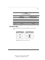
Package Contents
Before you start to install the hub, verify that this package contains the
following items:
Q
Compaq HB1004 10Base-T Ethernet hub
Q
Communication cable
Q
Adapter connectors
Q
Power cord
Q
Rack-mounting kit (two mounting brackets, eight 3/8-inch bracket
screws, and four ½-inch rack-mount screws)
Q
Four adhesive-backed rubber feet
Q
Compaq HB1004 System Configuration Program diskette
Q
Compaq HB1004 10Base-T Ethernet Hub User Guide
Q
Warranty guide
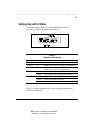
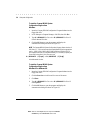
Figure 1-1 Package Contents

. . . . . . . . . . . . . . . . . . . . . . . . . . . . . .
1-3
Compaq HB1004 10Base-T Hub User Guide
Writer:
Weldon W. Rowan
Project:
Overview
Comments:
File Name:
SAB_1.DOC
Last Saved On:
7/2/98 8:29 AM
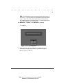
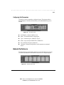
Hub Components
This section provides an overview of the Compaq HB1004 hub’s components
including the LED indicators, RJ-45 ports, and the serial COM port. Figure 1-1
shows the hub’s front panel.
Figure 1-1 Compaq HB1004 10Base-T Ethernet Hub Front Panel
RJ-45 Ports
The hub’s four RJ-45 ports allow connections to workstations and servers in a
10Base-T network via UTP cabling. When the MDI/MDI-X slide switch on the
front panel of the hub is set to MDI, Port 4 uses the MDI pinout and can be
used for a 10Base-T uplink. When the switch is set to MDI-X, Port 4 uses the
MDI-X pinout and can be connected directly to a network interface card (NIC).
Serial COM Port
The HB1004 hub contains a serial COM port that uses a male DB9 connector
with a standard AT pinout. You can use this port to connect to a workstation
for out-of-band communication using the Compaq HB1004 System
Configuration Program.
LED Indicators
The LED panel of the hub helps you monitor the hub’s operation. When you
power on the hub, it performs a power-on self test (POST) which lasts a few
seconds. After the POST, all LEDs reflect the current operational modes
described in Table 1-1.

. . . . . . . . . . . . . . . . . . . . . . . . . . . . . .
1-4
Overview
Writer:
Weldon W. Rowan
Project:
Overview
Comments:
File Name:
SAB_1.DOC
Last Saved On:
7/2/98 8:29 AM
Unit LEDs
The unit-level LEDs on the HB1004 indicate the status of the power supply and
the percentage of use and collisions on the hub.
Table 1-1
Hub LED Conditions and Descriptions
LED Status Description
Power On Power supply is operational
Off Power supply is off
Utilization Indicates percentage of network utilization
1 Green lit 1% to 5%
2 Green lit 5% to 15%
3 Green lit 15% to 30%
3 Green, 1 Amber lit 30% to 65%
3 Green, 2 Amber lit Above 65%
Collision Indicates percentage of network collision count variation
1 Green lit 1% to 3%
2 Green lit 3% to 5%
3 Green lit 5% to 10%
3 Green, 1 Amber lit 10% to 15%
3 Green, 2 Amber lit Above 15%

. . . . . . . . . . . . . . . . . . . . . . . . . . . . . .
1-5
Compaq HB1004 10Base-T Hub User Guide
Writer:
Weldon W. Rowan
Project:
Overview
Comments:
File Name:
SAB_1.DOC
Last Saved On:
7/2/98 8:29 AM
Port LEDs
There are two LEDs for each port to indicate link/activity and partition/disable
on the ports.
Table 1-2
Port LED Conditions and Descriptions
LED Status Description
Link/Activity Solid green A network device has established a link with the hub
Flashing green
Data is passing through the port, flashes in proportion to
rate of traffic passing through the port
Partition/Disable Solid Amber Indicates the port is partitioned
Flashing Amber Indicates the port has been disabled by management
Off The port is operating normally
MDI/MDI-X Slide Switch
The MDI/MDI-X slide switch is located on the front panel of the hub. This
switch allows you to use Port 4 as an uplink port to connect the hub to another
hub or switch. When the switch is in the MDI position, Port 4 uses the MDI
pinout for an uplink port. When the switch is in the MDI-X position, Port 4
uses the MDI-X pinout to connect to a workstation or server NIC.

. . . . . . . . . . . . . . . . . . . . . . . . . . . . . .
2-1
Compaq HB1004 10Base-T Hub User Guide
Writer:
Weldon W. Rowan
Project:
Installation
Comments:
File Name:
SAB_2.DOC
Last Saved On:
7/2/98 8:49 AM
Chapter 2
Installation
This chapter provides information to help you prepare for and install the hub
and connect the hub to the network.
Mounting the Hub
You can place this hub directly on a desktop or mount it in a rack. Before you
start installing the hub, make sure you can provide the right operating
environment, including power requirements, sufficient physical space, and
proximity to other network devices you want to connect. Verify the following
installation requirements:
Q
Power requirements: 100 to 240 VAC (+/- 10%) at 50 to 60 Hz (+/- 3
Hz). The hub’s power supply automatically adjusts to the input voltage.
Q
The hub should be located in a cool, dry place with at least 10 cm (4 in.)
of space at the front and back for ventilation.
Q
Place the hub out of direct sunlight and away from heat sources or areas
with a high amount of electromagnetic interference.
Q
If you intend to mount the hub in a rack, make sure you have all the
necessary mounting screws, brackets, and tools.
Q
Check if network cables and connectors needed for installation are
available.
Mounting the Hub on a Flat Surface
This hub can be placed anywhere there is enough flat space, such as on a table
or desktop.
1.
Stick the self-adhesive rubber foot pads (that come with this package) on
each of the four concave spaces located on the bottom of the hub
2.
Place the hub on a firm, flat surface.
3.
Be sure you allow at least 2 inches (5 cm) on each side and 4 inches (10
cm) at the back of the hub for proper airflow.

. . . . . . . . . . . . . . . . . . . . . . . . . . . . . .
2-2
Installation
Writer:
Weldon W. Rowan
Project:
Installation
Comments:
File Name:
SAB_2.DOC
Last Saved On:
7/2/98 8:49 AM
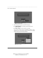
Mounting the Hub in a Rack
To mount the hub in a rack, follow these steps:
1. Use a standard EIA 19 inch rack
2. Use the brackets and screws supplied in the rack mounting kit
3. Use a cross-head screwdriver to attach the brackets to the side of the hub
Figure 2-1 Attaching the Mounting Brackets
4. Position the hub in the rack by lining up the holes in the brackets with
the appropriate holes on the rack, and then use the supplied screws to
mount the hub in the rack
Figure 2-2 Positioning the Hub in a Rack

. . . . . . . . . . . . . . . . . . . . . . . . . . . . . .
2-3
Compaq HB1004 10Base-T Hub User Guide
Writer:
Weldon W. Rowan
Project:
Installation
Comments:
File Name:
SAB_2.DOC
Last Saved On:
7/2/98 8:49 AM
Connecting the Hub System
The Compaq HB1004 hub has four RJ-45 ports, one of which serves as an
MDI/MDI-X port.
Making a Connection via an MDI-X Port
You can connect any RJ-45 (MDI-X) station port on the hub to any device that
uses a standard network interface such as a PC or server. You can also connect
to an MDI-X port of a network interconnection device such as a bridge or router
by using a cross-over cable.
1. Prepare the network devices you wish to network. Make sure you have
installed 10Base-T network interface cards for connecting to the hub’s
RJ-45 (MDI-X) station ports. You also need to prepare straight-through
shielded or unshielded twisted-pair cables with RJ-45 plugs at both ends.
Use 100Ω Category 3, 4, or 5 cable for all RJ-45 connections.
2. Connect one end of the cable to the RJ-45 port of the network interface
card, and the other end to any available (MDI-X) station port on the hub.
When inserting an RJ-45 plug, be sure the tab on the plug clicks into
position to ensure that it is properly seated. Using the hub in a stand-
alone configuration, you can network up to four end nodes.
RJ-45
Connector
Figure 2-3 Inserting an RJ-45 Connector

. . . . . . . . . . . . . . . . . . . . . . . . . . . . . .
2-4
Installation
Writer:
Weldon W. Rowan
Project:
Installation
Comments:
File Name:
SAB_2.DOC
Last Saved On:
7/2/98 8:49 AM
WARNING:
Do not plug a phone jack connector into any RJ-45 port.
This may damage the hub. Instead, use only twisted-pair cables with
RJ-45 connectors
.
NOTES:
1. Make sure each twisted-pair cable does not exceed 100 meters (328 feet)
2. When using Port 4 as an MDI-X port, set the port selection switch to MDI-X
Making a Connection via the MDI/MDI-X Port
(Port 4)
1. To make a direct connection to a compatible hub or switch, use the
MDI/MDI-X port (Port 4). When connecting to this port, remember to
set the port selection switch to MDI. You can also connect any RJ-45
(MDI-X) port on the hub to an MDI/MDI-X port on the other device
when the other device’s port is set to MDI.
2. Prepare straight-through shielded or unshielded twisted-pair cables with
RJ-45 plugs at both ends. Use 100Ω Category 3, 4, or 5 cable for all RJ-
45 connections. When inserting an RJ-45 plug, be sure the tab on the
plug clicks into position to ensure that it is properly seated.
NOTES:
1. To connect to another hub or switch, you may also attach to (MDI-X)
station ports at both ends if you use a crossover cable.
2. When using Port 4 as an MDI port, set the port selection switch to
MDI.
3. When connecting to another 10Mb/s hub, you can cascade up to four
hubs, and use up to 100 meters (328 feet) of cable between each
inter-hub link.
Powering On the Hub
1. Plug the power cord into the power socket at the rear of the hub, and the
other end into a power outlet (see Figure 2-4).
2. Turn on the power switch on the back of the hub ( I = on; 0 = off).

. . . . . . . . . . . . . . . . . . . . . . . . . . . . . .
2-5
Compaq HB1004 10Base-T Hub User Guide
Writer:
Weldon W. Rowan
Project:
Installation
Comments:
File Name:
SAB_2.DOC
Last Saved On:
7/2/98 8:49 AM
O
I
Figure 2-4 Connecting the Power Cord
3.
Check the LED marked PWR on the front panel to see if it is on. The
unit will automatically select the setting that matches the connected
input voltage. Therefore, no additional adjustments are necessary when
connecting it to any input voltage within the specified range. See
Appendix A for power requirements.
4.
The hub performs a self-diagnostic test upon power-on.

. . . . . . . . . . . . . . . . . . . . . . . . . . . . . .
2-6
Installation
Writer:
Weldon W. Rowan
Project:
Installation
Comments:
File Name:
SAB_2.DOC
Last Saved On:
7/2/98 8:49 AM
Diagnostic Tests
After power on, the hub automatically performs a diagnostic self-test. During
this test, port status LEDs indicate the success or failure of each test.
The system tests each component one at a time. At the completion of the test, if
no diagnostic LEDs are lit, then all components passed the test. If a component
fails the test, the corresponding LED will continue blinking. The following
table identifies the component that corresponds to each diagnostic test LED.
Figure 2-5 Power On Self Test Diagnostic LEDs
Table 2-1
LED Diagnostic Test Functions
LED Series LED Number Test Function/Component
Partition/Disable 1 CPU
2 Flash ROM 1
3SRAM
4 LAN Controller
Link/Activity 1 HUB Controller
2 Serial Port RS232 Controller
3 EEPROM
4 Flash ROM 2

. . . . . . . . . . . . . . . . . . . . . . . . . . . . . .
2-7
Compaq HB1004 10Base-T Hub User Guide
Writer:
Weldon W. Rowan
Project:
Installation
Comments:
File Name:
SAB_2.DOC
Last Saved On:
7/2/98 8:49 AM
Verifying Hub and Port Status
After the hub completes the POST, you can check hub activity and each
connection by comparing the indicators with Table 2-2.
Figure 2-6 HB1004 Hub and Port LEDs
Table 2-2
Hub and Port LED Indicators
LED State Indication
Power On Hub receiving power, CPU running
Utilization% On Number of LEDs lit indicates percentage of LAN bandwidth used
Collision% On Two or more devices attempted to transmit data at the same time,
number of LEDs lit indicates percentage of collisions
Link/Activity On Port has established a valid network connection
Flashing Port is receiving packets; blinking proportional to traffic
Partition/Disable On Port partitioned due to an abnormal network condition
Flashing Port has been disabled by management
Off Port is operating normally
Table 1-1 in Chapter 1 explains the LED system for indicating percentages for
Utilization and Collisions.

. . . . . . . . . . . . . . . . . . . . . . . . . . . . . .
2-8
Installation
Writer:
Weldon W. Rowan
Project:
Installation
Comments:
File Name:
SAB_2.DOC
Last Saved On:
7/2/98 8:49 AM
Applications
This hub is not only designed to provide network access for 10Mb/s
connections, but also to provide options in setting up network connections. It
can be used as a simple stand-alone hub or can be cascaded to any compatible
hub or switch. A sample configuration diagram is shown in Figure 2-7.
Figure 2-7 A Sample Application Using the HB1004 10Base-T Ethernet Hub

. . . . . . . . . . . . . . . . . . . . . . . . . . . . . .
3-1
Compaq HB1004 10Base-T Hub User Guide
Writer:
Weldon W. Rowan
Project:
Setup and Configuration
Comments:
File Name:
SAB_3.DOC
Last Saved On:
7/2/98 4:53 PM
Chapter 3
Setup and Configuration
Preparing for Configuration
Management
There are two methods for configuring the Compaq HB1004 - using the out-of-
band program or using in-band network management software (not supplied).
The diskette included with the Compaq HB1004 contains the menu-driven
Compaq HB1004 System Configuration Program. To use this program, make a
direct PC or modem connection to the serial port on the front of the hub.
Out-of-Band Connection
Out-of-band configuration requires a computer as your workstation. There are
two valid connection types to the hub:
Q
Out-of-band onsite connection - The workstation, normally within the
vicinity of the hub, is directly connected to the serial port on the hub.
Q
Out-of-band modem connection - The workstation is connected to the
remote hub via a modem.
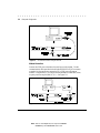
Onsite Connection
Attach a PC to the serial port on the hub. Use the communication cable (and
DB9 to RJ-45 converters) provided with this package. Configure the PC’s
serial port for 9600 baud, 8 bits, no parity, and one stop bit (9600, 8, N, 1). See
Figure 3-1.
NOTE
: Some PCs may have a 25 pin serial port. For these PCs use the DB25 to
RJ-45 converter supplied with the hub instead of the DB9 to RJ-45 converter
mentioned above to connect the PC.

. . . . . . . . . . . . . . . . . . . . . . . . . . . . . .
3-2
Setup and Configuration
Writer:
Weldon W. Rowan
Project:
Setup and Configuration
Comments:
File Name:
SAB_3.DOC
Last Saved On:
7/2/98 4:53 PM
Figure 3-1. Out-of-Band Connection Using an Onsite PC
Modem Connection
Connect the COM port on the hub to the serial port on the modem. Use the
communications cable provided with the hub and DB9/25 to RJ-45 converters
as needed. At the remote site, connect the PC’s COM port to the remote
modem. Configure the PC’s COM port and the modems for 9600 baud, 8 bits,
no parity, and one stop bit (9600, 8, N, 1). See Figure 3-2.
Figure 3-2. Out-of-Band Connection Using a Remote PC and Modem
Page is loading ...
Page is loading ...
Page is loading ...
Page is loading ...
Page is loading ...
Page is loading ...
Page is loading ...
Page is loading ...
Page is loading ...
Page is loading ...
Page is loading ...
Page is loading ...
Page is loading ...
Page is loading ...
Page is loading ...
Page is loading ...
Page is loading ...
Page is loading ...
Page is loading ...
Page is loading ...
Page is loading ...
Page is loading ...
Page is loading ...
Page is loading ...
Page is loading ...
-
 1
1
-
 2
2
-
 3
3
-
 4
4
-
 5
5
-
 6
6
-
 7
7
-
 8
8
-
 9
9
-
 10
10
-
 11
11
-
 12
12
-
 13
13
-
 14
14
-
 15
15
-
 16
16
-
 17
17
-
 18
18
-
 19
19
-
 20
20
-
 21
21
-
 22
22
-
 23
23
-
 24
24
-
 25
25
-
 26
26
-
 27
27
-
 28
28
-
 29
29
-
 30
30
-
 31
31
-
 32
32
-
 33
33
-
 34
34
-
 35
35
-
 36
36
-
 37
37
-
 38
38
-
 39
39
-
 40
40
-
 41
41
-
 42
42
-
 43
43
-
 44
44
-
 45
45


Ask a question and I''ll find the answer in the document
Finding information in a document is now easier with AI
Related papers
-
Compaq HB1004 User manual
-
-
-
-
-
-
-
-
-
Other documents
-
Black Box PIN POINT TS020A User manual
-
 TRIGEM CW3S20A User manual
-
ADTRAN Hub User manual
-
HP Compaq D315 Safety And Regulatory Information Manual
-
Accton Technology 24S User manual
-
MaxTech HX-5 User manual
-
-
D-Link DES-2212 User manual
-
EMS E36LRP2000 User manual
-
