Maytag MDE 1100AES User manual
- Category
- Washing machines
- Type
- User manual

MDE 1100AES
Use and Care Guide
Drying cabinet

Dear MAYTAG customer!
Congratulations on your excellent product choice and welcome to the Maytag
family. A global family with its roots in Scandinavia.
Cleaning results, design, environmental impact on nature and home, user
friendliness, low consumption of time, energy and water, a long life span,
reliability.... Good appliances should include all of these. And this is what we
try to give you.
When you buy an MAYTAG product, we want you to feel assured that the
inside is as good as the outside and that the ethics and morals on which we built
this machine are just as high as the quality and performance you get from it.
That is what Scandinavian quality is all about.
In order to get the best possible results from your machine and all its functions,
please read this Use and Care Guide before using the machine for the first
time.
And if you have any questions, please do not hesitate to call us or contact us
via our web site.
Best regards from Scandinavia and the people at Maytag.

3
Contents
Safety Instructions . . . . . . . . . . . . . . . 4
Symbols . . . . . . . . . . . . . . . . . . . . 4
I
mportant safety information . . . . . . 4
Description of the drying cabinet
. . . . 5
Control panel . . . . . . . . . . . . . . . . . . . . 6
Where to install it. . . . . . . . . . . . . . . . . 7
Electrical requirements . . . . . . . . . . . . 8
User’s responsibility . . . . . . . . . . . 8
Electrical connection . . . . . . . . . . . 8
Ventilation alternatives . . . . . . . . . . . . 9
Ventilation out into the room where
the drying cabinet is located . . . . 9
Connection to a vent duct . . . . . . 10
Installation . . . . . . . . . . . . . . . . . . . . . 12
Unpacking . . . . . . . . . . . . . . . . . . 12
Complete delivery includes . . . . . 12
Recommended tools . . . . . . . . . . 12
Placing the door the other way
round. . . . . . . . . . . . . . . . . . . . . . 13
Horizontal adjustment . . . . . . . . 14
Mounting . . . . . . . . . . . . . . . . . . . 14
Mounting into custom cabinetry
. . . 15
Ventilation connection . . . . . . . . . 17
Electrical connection . . . . . . . . . . 17
Final check . . . . . . . . . . . . . . . . . 18
How to use the drying cabinet . . . . . 19
Starting . . . . . . . . . . . . . . . . . . . . 19
Setting pause and restart . . . . . . 19
Stopping . . . . . . . . . . . . . . . . . . . 19
Loading . . . . . . . . . . . . . . . . . . . . 19
Some advice for users . . . . . . . . 20
Setting the temperature selector
knob . . . . . . . . . . . . . . . . . . . . . . 21
Care . . . . . . . . . . . . . . . . . . . . . . . . . . . 22
Cleaning the drying cabinet . . . . 22
When the drying cabinet is not in
use . . . . . . . . . . . . . . . . . . . . . . . 22
Trouble Shooting . . . . . . . . . . . . . . . . 23
Service . . . . . . . . . . . . . . . . . . . . . . . . 24
Technical information . . . . . . . . . . . . 25
Technical characteristics . . . . . . . 25
Evacuation/Air intake . . . . . . . . . 25
Energy consumption and drying
time . . . . . . . . . . . . . . . . . . . . . . 25
Manufacturing standards . . . . . . . 25
Air gap left during mounting . . . . 25
Personal notes. . . . . . . . . . . . . . . . . . 26

4
Safety Instructions
Advice and instructions about the
best way to use the product and avoid
operating disorders.
I
mportant safety information
The following advice and warnings have
been drawn up, so that you may avoid both
misusing the drying cabinet and the risk of
unnecessary accidents. So read the following
through very carefully before installing and
using the drying cabinet.
Read this Use and Care Guide before using
the drying cabinet.
Do not dry articles of clothing or similar
items which have just been treated with
petrol or some other volatile and inflam-
mable agent. This can result in the build
up of an explosive mixture of gases.
Do not allow children to play in or on the
drying cabinet. Keep an eye on children
when they are in the immediate vicinity of
the cabinet.
The drying cabinet should be installed or
kept in storage indoors.
Follow Asko’s recommendations concer-
ning repairs and spare part replacement.
If a softening agent or antistatic substance
is used, the manufacturer’s instructions
concerning the utilisation of the product
should be followed.
Do not use heat in the cabinet for products
containing foam rubber or similar material.
Follow the manufacturer’s washing and
drying instructions for such products very
carefully.
Keep the area around the evacuation duct
free from dust and dirt.
Regularly clean the inside of the drying
cabinet.
Keep this Use and Care Guide in a safe
place so that it will always be at hand
for future reference.
Symbols
WARNING
ATTENTION
Other important remarks
Indicates a risk of personal injuries or
serious damage to the product if the
instructions are not followed.
Read this manual very carefully and follow
the instructions provided. Especially important
information is indicated by the accompa-
nying symbols and text WARNING
or ATTENTION.

5
DC XXXX
2
1
3
4
5
6
7
8
10
11
12
13
9
Description of the drying cabinet
1. Exhaust collar
2. Drying cabinet model
3. Hanger hooks
4. Identification plate (inside)
5. Upper hanger section
6. Middle hanger section
7. Lower hanger section
8. Shoe rack
9. Air intake
10. Control panel
11. Door
12. Door hanger for lighter items
12. Glove hanger

6
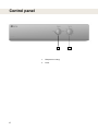
1
2
Control panel
1. Temperature setting
2. Timer

7
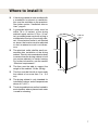
595 mm
640 mm
1730 mm
610 mm
Where to install it
If the drying cabinet is to be installed with
a connection to exhaust air ventilation,
this must be available on the premises.
See futher section “Ventilation alterna-
tives”, page 9.
A grounded electrical outlet must be
within 79 in. (2 meters) of the drying
cabinet’s upper section. A 79-in. (2-me-
ter) grounded power cord with a plug is
connected at the top of the drying cabi-
net. If the electrical outlet is not located
as above, the location must be adjusted
so that an extension cord is not neces-
sary.
The electrical outlet shall be easily ac-
cessible after installation of the drying
cabinet. Take this into consideration even
in cases when the drying cabinet is built
into custom cabinetry or similar framing.
For further information, see the section
“Electrical requirements”.
The floor must be able to support the
weight of the cabinet 133 lbs (60 kg).
The floor must be flat with a slope under
the cabinet of no more than 1 in. (2.5
cm).
The drying cabinet is only intended for
installation indoors and at temperatures
above 0°C (32°F).
The drying cabinet may not be located in
environments where pressurized water
is used for cleaning.

8
Electrical requirements
Electrical connection
The drying cabinet must be connected to
a 230 Volt single-phase 50 Hz grounded
wall outlet. The electric outlet must be
installed and grounded in accordance
with regulations in force.
The drying cabinet is delivered complete
with connections, including a 2 metre
long cable with a grounded plug.
Do not change the flexible cord and plug
which come with the drying cabinet. If the
plug is not adapted to the electric outlet,
this problem should be put in the hands
of a qualified technician.
The drying cabinet should be connected
with the provided connector cable and
must not be permanently connected!
The electrical outlet should be placed in
such a way that the plug can easily be
pulled out whenever necessary.
WARNING
Check that mains supply complies with
the data on the identification plate and
also that the main lead is grounded in the
correct fashion, according to standards
in force. We recommend that the main
lead be provided with a circuit brea-
ker.
The connection shall be separately fu-
sed.
The manufacturer declines all responsi-
bility for any consequences if the electri-
cal connection is not made in the manner
laid down in this Use and Care Guide.
User’s responsibility
It is the responsibility of the user to contact a
qualified electrician if the electric outlet socket
is not easily accessible as laid down in this
manual
Connect to grounded wall outlet .
Do not use an adapter or an extension
cord.

9
1
2
1
2
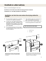
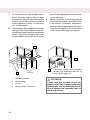
Ventilation alternatives
Minimum
300 mm
Ceiling
Do not hesitate to open doors or windows
in the room for optimum ventilation.
In the case of an inbuilt drying cabinet,
exchange the flexible ventilation hose
delivered with the cabinet (only certain
markets) for a rigid ventilation pipe of 100
mm in diameter.
The distance between the top edge of
the pipe and the ceiling should not be
less than 300 mm.
Ceiling
Minimum
300 mm
Moist air can be discharged in two ways:
Ventilation out into the room where the drying cabinet is located
Connection to a vent duct (exhaust air ventilation)
Ventilation out into the room where the drying cabinet is
located
The ventilation pipe must reach the out-
side of the cabinet mounting unit.
Be sure that there is a good supply of air
to the drying cabinet air intake orifice.
1. Humid air out
2. Air intake
The room must be well aired
Ventilation out into the room where the
drying cabinet is located. Built-in drying
cabinet in custom cabinetry
Ventilation out into the room where the
drying cabinet is located. Drying cabinet
not built in

10
1
2
3
4
5
6
Connection to a vent duct
The drying cabinet must not be
connected to the fireplace chimney
ATTENTION
When the cabinet is on, 45 m³ of humid air are
evacuated per hour. So make sure that air can
penetrate into the room to replace the humid
air given off by the drying cabinet.
With a draft stabilizer
The ventilation duct valve is replaced by a
draft stabilizer (included in the delivery).
See also the section ’Connect Ventilation’
page 17.
Do not assemble the ventilation duct
valve inside the drying cabinet
The drying cabinet can be connected to a vent duct in two ways:
1. Humid air out
2. Hose
3. Exhaust collar
4. Draft stabilizer
5. Air intake
6. Ventilation duct valve
The drying cabinet is connected to the
evacuation duct with a draft stabilizer

11
2
1
3
When the drying cabinet is permanently con-
nected to the vent duct, the entire room is
ventilated through the drying cabinet.
The ventilation duct valve is replaced by an
adapter (not included).
See also the section ’Connect Ventilation’
page 17.
1. Adapter
2. Air intake
3. Ventilation duct valve
The drying cabinet permanently installed
and connected to the evacuation duct
Permanently installed and connected to a vent duct (only certain
markets)
Only the evacuation hose delivered
with the cabinet must be used. (For
the markets where such an article is
included)
ATTENTION
Do not assemble the ventilation duct
valve inside the drying cabinet.

12
Installation
Take off all the packing material; do not
use a sharp tool which could damage the
product.
Check that the drying cabinet has not
been damaged during transportation.
The distributor should be notified of any
damage during transportation within 7
days.
The cabinet can easily tip over since it
is not yet solidly screwed into place.
The packing material such as plastic
or frigolite should be kept out of
children´s way.
Unpacking
WARNING
WARNING
After unpacking, check that the drying
cabinet is free from defects. The distribu-
tor should immediately be notified of any
damage, defects or even missing parts.
Check that all the safety devices used
for transportation have been removed
before the drying cabinet is connected.
Complete delivery includes
The cabinet with the fan unit
Flexible hose for ventilation (only certain
markets)
Exhaust collar with 2 attachment
screws
Draft stabilizer (only certain markets)
Attachment screws (2 screws, washers
and protective caps) for firmly fixing the
cabinet to the wall
Allen wrench and protective caps for the
adjustable feet
The Use and Care Guide for installation
and utilisation
Recommended tools
Bubble level
Tape measure
Hand drill
Screwdriver (Phillips)
An 8 mm diameter drill bit
Pencil
Protective gloves (if supplied)

13
1
2
The door can be hung on its hinges on the
left or the right.
1. Lay the drying cabinet on its back side.
2. Disengage the hinge pin of the bottom
hinge (1) and lift the door off.
3. Take off the plastic plug and press it
right down on to the bottom hinge on the
opposite side.
4. Disengage the hinge pin of the upper hinge
(2) and place it on the opposite side.
5. Completely unscrew the glove hangers
on the inside of the door and turn them
completely around. The glove hangers are
fastened into place with four screws.
6. Rotate the door, fi t it into place and fi x it
fi rmly by means of the lower hinge pin
(1).
Placing the door the other way round

14
2
3
1
2
1
Horizontal adjustment
1. Lift out the shoe rack.
2. Control that surfaces are horizontal by
placing a bubble level parallel to the walls
and parallel to the back and the door.
3. Use the Allen wrench provided, and cor-
rect the position of all four adjustable feet
through the holes in the base plate of the
drying cabinet (use pliers if necessary).
4. Press the four protective caps down firmly
into the holes.
1. Shoe rack
2. Bubble level
3. Allen wrench
Mounting
1. Take out the upper hanging section and
mark the centres of the holes on the woo-
den strip (see the section “Installing in
the cabinet mounting unit”) or on the wall
behind the drying cabinet.
2. Pre-drill the holes in the spacer bead for
the attachment screws.
3. Fix the cabinet in place using the provided
screws with their matching washers.
4. In the same way, fix the protective caps
provided over the screw heads.
1. Pre-drilled hole
2. 2 attachment screws with washers
WARNING
The cabinet should not be used without
being screwed to the wall.

15
1
2
3
4
5
1. Keep the adhesive tape on the door until the
drying cabinet is in place. Place the cabinet
so that its front is properly aligned with the
cabinetry facing.
2.
Plug the connection cord into the socket and
take care to be sure that the cord is not stuck
and can easily be unplugged.
3. Take off the adhesive tape and open the
door. Draw out the upper hanging section.
Measure and note down the distance bet-
ween the back wall of the drying cabinet
and the wall behind the drying cabinet. See
fi gure Measurement ’A’.
4. Mark the position of the holes on the back
wall with a pencil.
5. Push back the hanging section, shut the
door and hold it in place with adhesive tape.
Pull out the entire drying cabinet.
6. Use a wooden strip of thickness “A”, accor-
ding to point 3, as a spacer. The wooden
strip must:
a) be divided into two parts to allow free
passage of air behind the drying cabinet.
Their length should be ~150 mm
b) be at least 10 mm thick.
Place the drying cabinet so that its
front fi ts well into the cabinet mounting
unit.
1. Minimum air gap 10 mm between
drying cabinet and mounting unit (abo-
ve and behind the drying cabinet)
2. Tape measure
3. Assembly holes
4. Drying cabinet back wall
5. Wall behind the drying cabinet
Mounting into custom cabinetry

16
1
2
3
4
7. Fix the two parts of the wooden strip in
place using two screws, each of them
screwed into the wall behind the drying
cabinet, so that they correspond with the
holes marked as in point 4. Use screws
of a suitable length.
8. Push back the drying cabinet into its final
location. Take off the adhesive tape hol-
ding the door and check that the wooden
strip is in place on the back wall of the
drying cabinet. Also check that the front
1. Attachment screws
2. Hole marking
3. Air flow
4. Wooden strip (in two parts)
part of the drying cabinet fits well into the
custon cabinetry..
9. Adjust the position of the drying cabinet
horizontally according to the instructions
in the section ”Horizontal adjustment”
and screw the drying cabinet firmly down
into place according to the instructions
in the section ”Mounting” on page 14.
~150 mm
The custom cabinetry with assembled
wooden strip, divided into two parts, to
allow free passage of air
ATTENTION
Check that the wooden strips are
properly and firmly in place in the back
wall and also that the assembly screws
do not obstruct the assembly holes in
the drying cabinet.

17
1
Ventilation connection
If the drying cabinet is installed in a
custom cabinetry, fit the exhaust collar
through the vent opening in the upper
part of the cabinetry when the drying
cabinet is moved to its final location.
1. Place the exhaust collar over the hole in
the drying cabinet’s top plate, align the
screw holes and screw the exhaust collar
into place.
2. Connect the vent pipe if the drying cabi-
net is built in, or press the supplied (only
certain markets) flexible hose into place.
See the section ’Ventilation requirements’
on page 9.
1. Exhaust collar
Electrical connection
Consult the earlier section ’Electrical require-
ments’, on page 8.
The exhaust collar is designed to be
screwed in place with two screws to
the drying cabinet’s top plate. There are
predrilled holes in the exhaust collar
and top plate.

18
1. Check that all parts are mounted. If not
- go through all the steps once more.
2. Check that no packing material is left lying
around.
3. Use a mild washing up product with warm
water and wash the drying cabinet inside
and out. Dry it carefully. See also the sec-
tion ’Care’ further on in the manual.
4. Put the plug in.
5. Read the section ’How to use the drying
cabinet’ further on in the manual.
6. Put the temperature selector knob on
’Normal’ position (full heat) and the time
selector knob on approximately 20 minu-
tes.
If the drying cabinet does not start,
check the following:
- that the door of the drying cabinet is
shut properly
- that the temperature and time selector
knobs are activated.
- that the drying cabinet is connected
to the mains electricity supply.
- that the fuse is in working order
7. When the drying cabinet has been on for
5 minutes, open the door and feel if it is
giving out heat.
If the cabinet is not giving out any
heat, even though the temperature
selector knob is activated and the fan
is functioning, turn the temperature
selector knob back to zero and wait
30 minutes. Then try again by first
putting the temperature selector knob
on ’Normal’ and then start the fan by
turning on the time selector knob. See
also the section ’Troubleshooting’.
Final check

19
How to use the drying cabinet
Starting
1. Place the articles to be dried in the drying
cabinet and shut the door. See also the
section ”Loading”.
2. Set an appropriate temperature and drying
time. See the section ’Setting the tempe-
rature selector knob’.
Stopping
Open the door and turn the time switch back
to ’0’.’
Setting pause and restart
Pause: Open the door
Restart: Shut the door.
Loading
In the cabinet there are three sections with
hangers.Every section has a number of rods
on which to hang the items.
The optimised hanging system has extensible
hangers. This system lightens the work for
those who hang up the items and spares both
their back and shoulders.
Hang the articles in the drying cabinet
according to how much room they take
up - not according to their weight.
For optimum efficiency - do not lay artic-
les flat on the upper hanging section.
Long clothes nearest to the walls of the
cabinet and shorter ones towards the
centre. By hanging the items in this way
the most efficient drying results are at-
tained.
Turn up the two lower hanging sections
if long clothes are to be dried.
Hang gloves, caps, scarves and suchlike
on the hanging bars on the inside of the
door.
Draw forward the upper hanging section
hanger hooks in order to hang up the
items more easily. Put it back when it is
not being used.
If you have made a pause in the drying
process, when it starts again, the
drying cabinet carries on from the
position it was at when the drying
cycle was interrupted. If you want to
completely stop the set drying cycle,
the time switch is put back to ’0’.

20
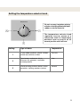
Some advice for users
Setting the controls
Set the temperature and the time selec-
tor knobs for the most delicate articles
to be dried.
The temperature is changed by means
of the temperature selector knob which
can be turned in both directions.
Drying
Always follow the washing instructions
on clothes if such instructions are avai-
lable.
If a softening agent or antistatic sub-
stance is used, the manufacturer’s ins-
tructions concerning the utilisation of the
product should be followed.
Remove items from the drying cabinet as
soon as they are dry. This reduces the dry-
ing time for the remaining damp garments.
Do not overload the drying cabinet. The
items will become creased and drying
uneven. Instead, leave a certain distance
between items of washing, if this is pos-
sible
If there is a risk that certain articles give
off their colour, free space should be left
around them.
Avoid drying thick clothes at the same
time as lighter articles for they have
completely different drying times.
Remember not to hang knitted articles.
These can be needlessly stretched when
they are heavy with water.
When the drying cabinet is cold, it
may happen that the sealing strip on
the door does not close completely.
However, this is fully compensated
for when the cabinet is in operation
since, with warmth, the sealing strip
expands.
The figure shows the airflow
inside the cabinet
Page is loading ...
Page is loading ...
Page is loading ...
Page is loading ...
Page is loading ...
Page is loading ...
Page is loading ...
Page is loading ...
-
 1
1
-
 2
2
-
 3
3
-
 4
4
-
 5
5
-
 6
6
-
 7
7
-
 8
8
-
 9
9
-
 10
10
-
 11
11
-
 12
12
-
 13
13
-
 14
14
-
 15
15
-
 16
16
-
 17
17
-
 18
18
-
 19
19
-
 20
20
-
 21
21
-
 22
22
-
 23
23
-
 24
24
-
 25
25
-
 26
26
-
 27
27
-
 28
28


Maytag MDE 1100AES User manual
- Category
- Washing machines
- Type
- User manual
Ask a question and I''ll find the answer in the document
Finding information in a document is now easier with AI
Related papers
-
Maytag MCE8000AYW User manual
-
-
-
Whirlpool MGD6300TQ - Bravos Gas Dryer Specification
-
-
-
Whirlpool G32026PELB User manual
-
-
 Maytag Services MED5707T User manual
-

Other documents
-
SEVERIN KS9827 Datasheet
-
 suptek MT4204 User manual
-
 suptek Tilt TV Wall Mount Bracket for 32-70 inch LED, LCD and Plasma TV, Mount User manual
-
 ferm LIVING Pujo Hanging Coat Rack NEW Assembly Manual
-
Asko DC7774 User manual
-
Haier GDZ5.0-1 User manual
-
Equator EW 824 & ED 850 User guide
-
Panda PAN760SFT Installation guide
-
-


