Page is loading ...
DS-64M Swingarc
Processes
12 and 16 Foot
™
MIG (GMAW) Welding
Pulsed MIG (GMAW-P)
Flux Cored (FCAW) Welding
OM-1588 161 875S
2006−05
Description
Wire Feeder
(Use with CC/CV Power Sources)
Visit our website at
www.MillerWelds.com
File: MIG (GMAW)

Miller Electric manufactures a full line
of welders and welding related equipment.
For information on other quality Miller
products, contact your local Miller distributor to receive the latest full
line catalog or individual specification sheets. To locate your nearest
distributor or service agency call 1-800-4-A-Miller, or visit us at
www.MillerWelds.com on the web.
Thank you and congratulations on choosing Miller. Now you can get
the job done and get it done right. We know you don’t have time to do
it any other way.
That’s why when Niels Miller first started building arc welders in 1929,
he made sure his products offered long-lasting value and superior
quality. Like you, his customers couldn’t afford anything less. Miller
products had to be more than the best they could be. They had to be the
best you could buy.
Today, the people that build and sell Miller products continue the
tradition. They’re just as committed to providing equipment and service
that meets the high standards of quality and value established in 1929.
This Owner’s Manual is designed to help you get the most out of your
Miller products. Please take time to read the Safety precautions. They
will help you protect yourself against potential hazards on the worksite.
We’ve made installation and operation quick
and easy. With Miller you can count on years
of reliable service with proper maintenance.
And if for some reason the unit needs repair,
there’s a Troubleshooting section that will
help you figure out what the problem is. The
parts list will then help you to decide the
exact part you may need to fix the problem.
Warranty and service information for your
particular model are also provided.
Miller is the first welding
equipment manufacturer in
the U.S.A. to be registered to
the ISO 9001:2000 Quality
System Standard.
Working as hard as you do
− every power source from
Miller is backed by the most
hassle-free warranty in the
business.
From Miller to You
Mil_Thank 4/05

TABLE OF CONTENTS
SECTION 1 − SAFETY PRECAUTIONS - READ BEFORE USING 1 . . . . . . . . . . . . . . . . . . . . . . . . . . . . . . . . . . .
1-1. Symbol Usage 1 . . . . . . . . . . . . . . . . . . . . . . . . . . . . . . . . . . . . . . . . . . . . . . . . . . . . . . . . . . . . . . . . . . . . . . . .
1-2. Arc Welding Hazards 1 . . . . . . . . . . . . . . . . . . . . . . . . . . . . . . . . . . . . . . . . . . . . . . . . . . . . . . . . . . . . . . . . . .
1-3. Additional Symbols For Installation, Operation, And Maintenance 3 . . . . . . . . . . . . . . . . . . . . . . . . . . . . .
1-4. California Proposition 65 Warnings 3 . . . . . . . . . . . . . . . . . . . . . . . . . . . . . . . . . . . . . . . . . . . . . . . . . . . . . . .
1-5. Principal Safety Standards 4 . . . . . . . . . . . . . . . . . . . . . . . . . . . . . . . . . . . . . . . . . . . . . . . . . . . . . . . . . . . . .
1-6. EMF Information 4 . . . . . . . . . . . . . . . . . . . . . . . . . . . . . . . . . . . . . . . . . . . . . . . . . . . . . . . . . . . . . . . . . . . . . .
SECTION 2 − CONSIGNES DE SÉCURITÉ − À LIRE AVANT UTILISATION 5 . . . . . . . . . . . . . . . . . . . . . . . . . .
2-1. Signification des symboles 5 . . . . . . . . . . . . . . . . . . . . . . . . . . . . . . . . . . . . . . . . . . . . . . . . . . . . . . . . . . . . .
2-2. Dangers relatifs au soudage à l’arc 5 . . . . . . . . . . . . . . . . . . . . . . . . . . . . . . . . . . . . . . . . . . . . . . . . . . . . . .
2-3. Autres symboles relatifs à l’installation, au fonctionnement et à l’entretien de l’appareil. 7 . . . . . . . . . . .
2-4. Principales normes de sécurité 8 . . . . . . . . . . . . . . . . . . . . . . . . . . . . . . . . . . . . . . . . . . . . . . . . . . . . . . . . . .
2-5. Information sur les champs électromagnétiques 8 . . . . . . . . . . . . . . . . . . . . . . . . . . . . . . . . . . . . . . . . . . . .
SECTION 3 − INTRODUCTION 9 . . . . . . . . . . . . . . . . . . . . . . . . . . . . . . . . . . . . . . . . . . . . . . . . . . . . . . . . . . . . . . . . .
3-1. Specifications 9 . . . . . . . . . . . . . . . . . . . . . . . . . . . . . . . . . . . . . . . . . . . . . . . . . . . . . . . . . . . . . . . . . . . . . . . .
SECTION 4 − INSTALLATION 9 . . . . . . . . . . . . . . . . . . . . . . . . . . . . . . . . . . . . . . . . . . . . . . . . . . . . . . . . . . . . . . . . . .
4-1. Installing Swivel Into Pipe Post 9 . . . . . . . . . . . . . . . . . . . . . . . . . . . . . . . . . . . . . . . . . . . . . . . . . . . . . . . . . .
4-2. Installing Control Box And Adjusting Tilt 10 . . . . . . . . . . . . . . . . . . . . . . . . . . . . . . . . . . . . . . . . . . . . . . . . . . .
4-3. Installing Boom And Reel Support 10 . . . . . . . . . . . . . . . . . . . . . . . . . . . . . . . . . . . . . . . . . . . . . . . . . . . . . . .
4-4. Installing Wire Guide Extension 11 . . . . . . . . . . . . . . . . . . . . . . . . . . . . . . . . . . . . . . . . . . . . . . . . . . . . . . . . .
4-5. Equipment Connection Diagram 12 . . . . . . . . . . . . . . . . . . . . . . . . . . . . . . . . . . . . . . . . . . . . . . . . . . . . . . . . .
4-6. Connecting Weld Cables And Gas Hoses 13 . . . . . . . . . . . . . . . . . . . . . . . . . . . . . . . . . . . . . . . . . . . . . . . . .
4-7. Control Box Connections 14 . . . . . . . . . . . . . . . . . . . . . . . . . . . . . . . . . . . . . . . . . . . . . . . . . . . . . . . . . . . . . . .
4-8. 14-Pin Plug Information 14 . . . . . . . . . . . . . . . . . . . . . . . . . . . . . . . . . . . . . . . . . . . . . . . . . . . . . . . . . . . . . . . .
4-9. Removing Safety Collar And Adjusting Boom 15 . . . . . . . . . . . . . . . . . . . . . . . . . . . . . . . . . . . . . . . . . . . . . .
4-10. Gun Recommendation Table 15 . . . . . . . . . . . . . . . . . . . . . . . . . . . . . . . . . . . . . . . . . . . . . . . . . . . . . . . . . . . .
4-11. Wire Type, Size, And Feed Speed Capability Table 15 . . . . . . . . . . . . . . . . . . . . . . . . . . . . . . . . . . . . . . . . .
4-12. Installing And Threading Welding Wire 16 . . . . . . . . . . . . . . . . . . . . . . . . . . . . . . . . . . . . . . . . . . . . . . . . . . . .
SECTION 5 − OPERATION 17 . . . . . . . . . . . . . . . . . . . . . . . . . . . . . . . . . . . . . . . . . . . . . . . . . . . . . . . . . . . . . . . . . . . .
5-1. Operational Terms 17 . . . . . . . . . . . . . . . . . . . . . . . . . . . . . . . . . . . . . . . . . . . . . . . . . . . . . . . . . . . . . . . . . . . .
5-2. Pulse Welding Terms 17 . . . . . . . . . . . . . . . . . . . . . . . . . . . . . . . . . . . . . . . . . . . . . . . . . . . . . . . . . . . . . . . . . .
5-3. Front Panel Controls 18 . . . . . . . . . . . . . . . . . . . . . . . . . . . . . . . . . . . . . . . . . . . . . . . . . . . . . . . . . . . . . . . . . . .
5-4. Side And Rear Panel Controls 18 . . . . . . . . . . . . . . . . . . . . . . . . . . . . . . . . . . . . . . . . . . . . . . . . . . . . . . . . . . .
SECTION 6 − SETTING SEQUENCE PARAMETERS 19 . . . . . . . . . . . . . . . . . . . . . . . . . . . . . . . . . . . . . . . . . . . . . .
6-1. Sequence Parameters In A Program 19 . . . . . . . . . . . . . . . . . . . . . . . . . . . . . . . . . . . . . . . . . . . . . . . . . . . . .
SECTION 7 − SETTING DUAL SCHEDULE PARAMETERS 20 . . . . . . . . . . . . . . . . . . . . . . . . . . . . . . . . . . . . . . . .
7-1. Selecting Dual Schedule Pair 20 . . . . . . . . . . . . . . . . . . . . . . . . . . . . . . . . . . . . . . . . . . . . . . . . . . . . . . . . . . .
7-2. Optional Dual Schedule Switch Diagrams 21 . . . . . . . . . . . . . . . . . . . . . . . . . . . . . . . . . . . . . . . . . . . . . . . . .
SECTION 8 − USING THE OPTIONAL DATA CARD 22 . . . . . . . . . . . . . . . . . . . . . . . . . . . . . . . . . . . . . . . . . . . . . . .
8-1. Data Card Terms 22 . . . . . . . . . . . . . . . . . . . . . . . . . . . . . . . . . . . . . . . . . . . . . . . . . . . . . . . . . . . . . . . . . . . . . .
8-2. Installing Data Card 22 . . . . . . . . . . . . . . . . . . . . . . . . . . . . . . . . . . . . . . . . . . . . . . . . . . . . . . . . . . . . . . . . . . .
8-3. Card Displays 23 . . . . . . . . . . . . . . . . . . . . . . . . . . . . . . . . . . . . . . . . . . . . . . . . . . . . . . . . . . . . . . . . . . . . . . . .
8-4. Entering Access Code 24 . . . . . . . . . . . . . . . . . . . . . . . . . . . . . . . . . . . . . . . . . . . . . . . . . . . . . . . . . . . . . . . . .
8-5. Security 25 . . . . . . . . . . . . . . . . . . . . . . . . . . . . . . . . . . . . . . . . . . . . . . . . . . . . . . . . . . . . . . . . . . . . . . . . . . . . .
SECTION 9 − SYSTEM SETUP 26 . . . . . . . . . . . . . . . . . . . . . . . . . . . . . . . . . . . . . . . . . . . . . . . . . . . . . . . . . . . . . . . . .
9-1. Accessing The Setup Menu 26 . . . . . . . . . . . . . . . . . . . . . . . . . . . . . . . . . . . . . . . . . . . . . . . . . . . . . . . . . . . . .
9-2. System Setup Display Parameters 27 . . . . . . . . . . . . . . . . . . . . . . . . . . . . . . . . . . . . . . . . . . . . . . . . . . . . . . .

TABLE OF CONTENTS
SECTION 10 − STANDARD PULSE WELDING PROGRAMS
FOR PHOENIX/INVISION 456 INVERTER
WELDING POWER SOURCES 28 . . . . . . . . . . . . . . . . . . . . . . . . . . . . . . . . . . . . . . . . . . . . . . . . . . . . . . . . . . . . . . . . .
10-1. Program 1 − Steel 28 . . . . . . . . . . . . . . . . . . . . . . . . . . . . . . . . . . . . . . . . . . . . . . . . . . . . . . . . . . . . . . . . . . . . .
10-2. Program 2 − Steel 28 . . . . . . . . . . . . . . . . . . . . . . . . . . . . . . . . . . . . . . . . . . . . . . . . . . . . . . . . . . . . . . . . . . . . .
10-3. Program 3 − Steel 28 . . . . . . . . . . . . . . . . . . . . . . . . . . . . . . . . . . . . . . . . . . . . . . . . . . . . . . . . . . . . . . . . . . . . .
10-4. Program 4 − Steel 29 . . . . . . . . . . . . . . . . . . . . . . . . . . . . . . . . . . . . . . . . . . . . . . . . . . . . . . . . . . . . . . . . . . . . .
10-5. Program 5 − Stainless Steel 29 . . . . . . . . . . . . . . . . . . . . . . . . . . . . . . . . . . . . . . . . . . . . . . . . . . . . . . . . . . . .
10-6. Program 6 − Stainless Steel 29 . . . . . . . . . . . . . . . . . . . . . . . . . . . . . . . . . . . . . . . . . . . . . . . . . . . . . . . . . . . .
10-7. Program 7 − Metal Core 29 . . . . . . . . . . . . . . . . . . . . . . . . . . . . . . . . . . . . . . . . . . . . . . . . . . . . . . . . . . . . . . . .
10-8. Program 8 − Metal Core 29 . . . . . . . . . . . . . . . . . . . . . . . . . . . . . . . . . . . . . . . . . . . . . . . . . . . . . . . . . . . . . . . .
SECTION 11 − STANDARD PULSE WELDING PROGRAMS
FOR XMT 304 INVERTER WELDING POWER SOURCES 30 . . . . . . . . . . . . . . . . . . . . . . . . . . . . . . . . . . . . . . . . . .
11-1. Program 1 − Steel 30 . . . . . . . . . . . . . . . . . . . . . . . . . . . . . . . . . . . . . . . . . . . . . . . . . . . . . . . . . . . . . . . . . . . . .
11-2. Program 2 − Steel 30 . . . . . . . . . . . . . . . . . . . . . . . . . . . . . . . . . . . . . . . . . . . . . . . . . . . . . . . . . . . . . . . . . . . . .
11-3. Program 3 − Steel 30 . . . . . . . . . . . . . . . . . . . . . . . . . . . . . . . . . . . . . . . . . . . . . . . . . . . . . . . . . . . . . . . . . . . . .
11-4. Program 4 − Stainless Steel 31 . . . . . . . . . . . . . . . . . . . . . . . . . . . . . . . . . . . . . . . . . . . . . . . . . . . . . . . . . . . .
11-5. Program 5 − Stainless Steel 31 . . . . . . . . . . . . . . . . . . . . . . . . . . . . . . . . . . . . . . . . . . . . . . . . . . . . . . . . . . . .
11-6. Program 6 − Stainless Steel 31 . . . . . . . . . . . . . . . . . . . . . . . . . . . . . . . . . . . . . . . . . . . . . . . . . . . . . . . . . . . .
11-7. Program 7 − Nickel Alloy 31 . . . . . . . . . . . . . . . . . . . . . . . . . . . . . . . . . . . . . . . . . . . . . . . . . . . . . . . . . . . . . . .
11-8. Program 8 − Metal Core 31 . . . . . . . . . . . . . . . . . . . . . . . . . . . . . . . . . . . . . . . . . . . . . . . . . . . . . . . . . . . . . . . .
SECTION 12 − SETTING SharpArcE CONTROL 32 . . . . . . . . . . . . . . . . . . . . . . . . . . . . . . . . . . . . . . . . . . . . . . . . . .
12-1. Selecting And Adjusting SharpArcE Control 32 . . . . . . . . . . . . . . . . . . . . . . . . . . . . . . . . . . . . . . . . . . . . . . .
SECTION 13 − TEACH POINTS 33 . . . . . . . . . . . . . . . . . . . . . . . . . . . . . . . . . . . . . . . . . . . . . . . . . . . . . . . . . . . . . . . .
13-1. Teach Using 15 Points 33 . . . . . . . . . . . . . . . . . . . . . . . . . . . . . . . . . . . . . . . . . . . . . . . . . . . . . . . . . . . . . . . . .
13-2. Redefining Teach Points 34 . . . . . . . . . . . . . . . . . . . . . . . . . . . . . . . . . . . . . . . . . . . . . . . . . . . . . . . . . . . . . . .
SECTION 14 − MAINTENANCE AND TROUBLESHOOTING 36 . . . . . . . . . . . . . . . . . . . . . . . . . . . . . . . . . . . . . . .
14-1. Routine Maintenance 36 . . . . . . . . . . . . . . . . . . . . . . . . . . . . . . . . . . . . . . . . . . . . . . . . . . . . . . . . . . . . . . . . . .
14-2. Motor Start Control 36 . . . . . . . . . . . . . . . . . . . . . . . . . . . . . . . . . . . . . . . . . . . . . . . . . . . . . . . . . . . . . . . . . . . .
14-3. Error Displays 37 . . . . . . . . . . . . . . . . . . . . . . . . . . . . . . . . . . . . . . . . . . . . . . . . . . . . . . . . . . . . . . . . . . . . . . . .
14-4. Troubleshooting 38 . . . . . . . . . . . . . . . . . . . . . . . . . . . . . . . . . . . . . . . . . . . . . . . . . . . . . . . . . . . . . . . . . . . . . .
SECTION 15 − ELECTRICAL DIAGRAM 40 . . . . . . . . . . . . . . . . . . . . . . . . . . . . . . . . . . . . . . . . . . . . . . . . . . . . . . . . .
SECTION 16 − PARTS LIST 42 . . . . . . . . . . . . . . . . . . . . . . . . . . . . . . . . . . . . . . . . . . . . . . . . . . . . . . . . . . . . . . . . . . .
OPTIONS AND ACCESSORIES
WARRANTY
OM-1588 Page 1
SECTION 1 − SAFETY PRECAUTIONS - READ BEFORE USING
som _3/05
Y Warning: Protect yourself and others from injury — read and follow these precautions.
1-1. Symbol Usage
Means Warning! Watch Out! There are possible hazards
with this procedure! The possible hazards are shown in
the adjoining symbols.
Y Marks a special safety message.
. Means “Note”; not safety related.
This group of symbols means Warning! Watch Out! possible
ELECTRIC SHOCK, MOVING PARTS, and HOT PARTS hazards.
Consult symbols and related instructions below for necessary actions
to avoid the hazards.
1-2. Arc Welding Hazards
Y The symbols shown below are used throughout this manual to
call attention to and identify possible hazards. When you see
the symbol, watch out, and follow the related instructions to
avoid the hazard. The safety information given below is only
a summary of the more complete safety information found in
the Safety Standards listed in Section 1-5. Read and follow all
Safety Standards.
Y Only qualified persons should install, operate, maintain, and
repair this unit.
Y During operation, keep everybody, especially children, away.
ELECTRIC SHOCK can kill.
Touching live electrical parts can cause fatal shocks
or severe burns. The electrode and work circuit is
electrically live whenever the output is on. The input
power circuit and machine internal circuits are also
live when power is on. In semiautomatic or automatic wire welding, the
wire, wire reel, drive roll housing, and all metal parts touching the
welding wire are electrically live. Incorrectly installed or improperly
grounded equipment is a hazard.
D Do not touch live electrical parts.
D Wear dry, hole-free insulating gloves and body protection.
D Insulate yourself from work and ground using dry insulating mats
or covers big enough to prevent any physical contact with the work
or ground.
D Do not use AC output in damp areas, if movement is confined, or if
there is a danger of falling.
D Use AC output ONLY if required for the welding process.
D If AC output is required, use remote output control if present on
unit.
D Additional safety precautions are required when any of the follow-
ing electrically hazardous conditions are present: in damp
locations or while wearing wet clothing; on metal structures such
as floors, gratings, or scaffolds; when in cramped positions such
as sitting, kneeling, or lying; or when there is a high risk of unavoid-
able or accidental contact with the workpiece or ground. For these
conditions, use the following equipment in order presented: 1) a
semiautomatic DC constant voltage (wire) welder, 2) a DC manual
(stick) welder, or 3) an AC welder with reduced open-circuit volt-
age. In most situations, use of a DC, constant voltage wire welder
is recommended. And, do not work alone!
D Disconnect input power or stop engine before installing or
servicing this equipment. Lockout/tagout input power according to
OSHA 29 CFR 1910.147 (see Safety Standards).
D Properly install and ground this equipment according to its
Owner’s Manual and national, state, and local codes.
D Always verify the supply ground − check and be sure that input
power cord ground wire is properly connected to ground terminal in
disconnect box or that cord plug is connected to a properly
grounded receptacle outlet.
D When making input connections, attach proper grounding conduc-
tor first − double-check connections.
D Frequently inspect input power cord for damage or bare wiring −
replace cord immediately if damaged − bare wiring can kill.
D Turn off all equipment when not in use.
D Do not use worn, damaged, undersized, or poorly spliced cables.
D Do not drape cables over your body.
D If earth grounding of the workpiece is required, ground it directly
with a separate cable.
D Do not touch electrode if you are in contact with the work, ground,
or another electrode from a different machine.
D Do not touch electrode holders connected to two welding ma-
chines at the same time since double open-circuit voltage will be
present.
D Use only well-maintained equipment. Repair or replace damaged
parts at once. Maintain unit according to manual.
D Wear a safety harness if working above floor level.
D Keep all panels and covers securely in place.
D Clamp work cable with good metal-to-metal contact to workpiece
or worktable as near the weld as practical.
D Insulate work clamp when not connected to workpiece to prevent
contact with any metal object.
D Do not connect more than one electrode or work cable to any
single weld output terminal.
SIGNIFICANT DC VOLTAGE exists in inverter-type
welding power sources after removal of input
power.
D Turn Off inverter, disconnect input power, and discharge input
capacitors according to instructions in Maintenance Section
before touching any parts.
Welding produces fumes and gases. Breathing
these fumes and gases can be hazardous to your
health.
FUMES AND GASES can be hazardous.
D Keep your head out of the fumes. Do not breathe the fumes.
D If inside, ventilate the area and/or use local forced ventilation at the
arc to remove welding fumes and gases.
D If ventilation is poor, wear an approved air-supplied respirator.
D Read and understand the Material Safety Data Sheets (MSDSs)
and the manufacturer’s instructions for metals, consumables,
coatings, cleaners, and degreasers.
D Work in a confined space only if it is well ventilated, or while
wearing an air-supplied respirator. Always have a trained watch-
person nearby. Welding fumes and gases can displace air and
lower the oxygen level causing injury or death. Be sure the breath-
ing air is safe.
D Do not weld in locations near degreasing, cleaning, or spraying op-
erations. The heat and rays of the arc can react with vapors to form
highly toxic and irritating gases.
D Do not weld on coated metals, such as galvanized, lead, or
cadmium plated steel, unless the coating is removed from the weld
area, the area is well ventilated, and while wearing an air-supplied
respirator. The coatings and any metals containing these elements
can give off toxic fumes if welded.
OM-1588 Page 2
Arc rays from the welding process produce intense
visible and invisible (ultraviolet and infrared) rays
that can burn eyes and skin. Sparks fly off from the
weld.
ARC RAYS can burn eyes and skin.
D Wear an approved welding helmet fitted with a proper shade of fil-
ter lenses to protect your face and eyes when welding or watching
(see ANSI Z49.1 and Z87.1 listed in Safety Standards).
D Wear approved safety glasses with side shields under your
helmet.
D Use protective screens or barriers to protect others from flash,
glare and sparks; warn others not to watch the arc.
D Wear protective clothing made from durable, flame-resistant mate-
rial (leather, heavy cotton, or wool) and foot protection.
Welding on closed containers, such as tanks,
drums, or pipes, can cause them to blow up. Sparks
can fly off from the welding arc. The flying sparks, hot
workpiece, and hot equipment can cause fires and
burns. Accidental contact of electrode to metal objects can cause
sparks, explosion, overheating, or fire. Check and be sure the area is
safe before doing any welding.
WELDING can cause fire or explosion.
D Remove all flammables within 35 ft (10.7 m) of the welding arc. If
this is not possible, tightly cover them with approved covers.
D Do not weld where flying sparks can strike flammable material.
D Protect yourself and others from flying sparks and hot metal.
D Be alert that welding sparks and hot materials from welding can
easily go through small cracks and openings to adjacent areas.
D Watch for fire, and keep a fire extinguisher nearby.
D Be aware that welding on a ceiling, floor, bulkhead, or partition can
cause fire on the hidden side.
D Do not weld on closed containers such as tanks, drums, or pipes,
unless they are properly prepared according to AWS F4.1 (see
Safety Standards).
D Connect work cable to the work as close to the welding area as
practical to prevent welding current from traveling long, possibly
unknown paths and causing electric shock, sparks, and fire
hazards.
D Do not use welder to thaw frozen pipes.
D Remove stick electrode from holder or cut off welding wire at
contact tip when not in use.
D Wear oil-free protective garments such as leather gloves, heavy
shirt, cuffless trousers, high shoes, and a cap.
D Remove any combustibles, such as a butane lighter or matches,
from your person before doing any welding.
D Follow requirements in OSHA 1910.252 (a) (2) (iv) and NFPA 51B
for hot work and have a fire watcher and extinguisher nearby.
FLYING METAL can injure eyes.
D Welding, chipping, wire brushing, and grinding
cause sparks and flying metal. As welds cool,
they can throw off slag.
D Wear approved safety glasses with side
shields even under your welding helmet.
BUILDUP OF GAS can injure or kill.
D Shut off shielding gas supply when not in use.
D Always ventilate confined spaces or use
approved air-supplied respirator.
HOT PARTS can cause severe burns.
D Do not touch hot parts bare handed.
D Allow cooling period before working on gun or
torch.
D To handle hot parts, use proper tools and/or
wear heavy, insulated welding gloves and
clothing to prevent burns.
MAGNETIC FIELDS can affect pacemakers.
D Pacemaker wearers keep away.
D Wearers should consult their doctor before
going near arc welding, gouging, or spot
welding operations.
NOISE can damage hearing.
Noise from some processes or equipment can
damage hearing.
D Wear approved ear protection if noise level is
high.
Shielding gas cylinders contain gas under high
pressure. If damaged, a cylinder can explode. Since
gas cylinders are normally part of the welding
process, be sure to treat them carefully.
CYLINDERS can explode if damaged.
D Protect compressed gas cylinders from excessive heat, mechani-
cal shocks, physical damage, slag, open flames, sparks, and arcs.
D Install cylinders in an upright position by securing to a stationary
support or cylinder rack to prevent falling or tipping.
D Keep cylinders away from any welding or other electrical circuits.
D Never drape a welding torch over a gas cylinder.
D Never allow a welding electrode to touch any cylinder.
D Never weld on a pressurized cylinder − explosion will result.
D Use only correct shielding gas cylinders, regulators, hoses, and fit-
tings designed for the specific application; maintain them and
associated parts in good condition.
D Turn face away from valve outlet when opening cylinder valve.
D Keep protective cap in place over valve except when cylinder is in
use or connected for use.
D Use the right equipment, correct procedures, and sufficient num-
ber of persons to lift and move cylinders.
D Read and follow instructions on compressed gas cylinders,
associated equipment, and Compressed Gas Association (CGA)
publication P-1 listed in Safety Standards.

OM-1588 Page 3
1-3. Additional Symbols For Installation, Operation, And Maintenance
FIRE OR EXPLOSION hazard.
D Do not install or place unit on, over, or near
combustible surfaces.
D Do not install unit near flammables.
D Do not overload building wiring − be sure power supply system is
properly sized, rated, and protected to handle this unit.
FALLING UNIT can cause injury.
D Use lifting eye to lift unit only, NOT running
gear, gas cylinders, or any other accessories.
D Use equipment of adequate capacity to lift and
support unit.
D If using lift forks to move unit, be sure forks are
long enough to extend beyond opposite side of
unit.
OVERUSE can cause OVERHEATING
D Allow cooling period; follow rated duty cycle.
D Reduce current or reduce duty cycle before
starting to weld again.
D Do not block or filter airflow to unit.
STATIC (ESD) can damage PC boards.
D Put on grounded wrist strap BEFORE handling
boards or parts.
D Use proper static-proof bags and boxes to
store, move, or ship PC boards.
MOVING PARTS can cause injury.
D Keep away from moving parts.
D Keep away from pinch points such as drive
rolls.
WELDING WIRE can cause injury.
D Do not press gun trigger until instructed to do
so.
D Do not point gun toward any part of the body,
other people, or any metal when threading
welding wire.
MOVING PARTS can cause injury.
D Keep away from moving parts such as fans.
D Keep all doors, panels, covers, and guards
closed and securely in place.
D Have only qualified persons remove doors,
panels, covers, or guards for maintenance as
necessary.
D Reinstall doors, panels, covers, or guards
when maintenance is finished and before re-
connecting input power.
READ INSTRUCTIONS.
D Read Owner’s Manual before using or servic-
ing unit.
D Use only genuine Miller/Hobart replacement
parts.
H.F. RADIATION can cause interference.
D High-frequency (H.F.) can interfere with radio
navigation, safety services, computers, and
communications equipment.
D Have only qualified persons familiar with
electronic equipment perform this installation.
D The user is responsible for having a qualified electrician prompt-
ly correct any interference problem resulting from the installa-
tion.
D If notified by the FCC about interference, stop using the
equipment at once.
D Have the installation regularly checked and maintained.
D Keep high-frequency source doors and panels tightly shut, keep
spark gaps at correct setting, and use grounding and shielding to
minimize the possibility of interference.
ARC WELDING can cause interference.
D Electromagnetic energy can interfere with
sensitive electronic equipment such as
computers and computer-driven equipment
such as robots.
D Be sure all equipment in the welding area is
electromagnetically compatible.
D To reduce possible interference, keep weld cables as short as
possible, close together, and down low, such as on the floor.
D Locate welding operation 100 meters from any sensitive elec-
tronic equipment.
D Be sure this welding machine is installed and grounded
according to this manual.
D If interference still occurs, the user must take extra measures
such as moving the welding machine, using shielded cables,
using line filters, or shielding the work area.
1-4. California Proposition 65 Warnings
Y Welding or cutting equipment produces fumes or gases which
contain chemicals known to the State of California to cause
birth defects and, in some cases, cancer. (California Health &
Safety Code Section 25249.5 et seq.)
Y Battery posts, terminals and related accessories contain lead
and lead compounds, chemicals known to the State of
California to cause cancer and birth defects or other
reproductive harm. Wash hands after handling.
For Gasoline Engines:
Y Engine exhaust contains chemicals known to the State of
California to cause cancer, birth defects, or other reproductive
harm.
For Diesel Engines:
Y Diesel engine exhaust and some of its constituents are known
to the State of California to cause cancer, birth defects, and
other reproductive harm.

OM-1588 Page 4
1-5. Principal Safety Standards
Safety in Welding, Cutting, and Allied Processes, ANSI Standard Z49.1,
from Global Engineering Documents (phone: 1-877-413-5184, website:
www.global.ihs.com).
Recommended Safe Practices for the Preparation for Welding and Cut-
ting of Containers and Piping, American Welding Society Standard
AWS F4.1 from Global Engineering Documents (phone:
1-877-413-5184, website: www.global.ihs.com).
National Electrical Code, NFPA Standard 70, from National Fire Protec-
tion Association, P.O. Box 9101, 1 Battery March Park, Quincy, MA
02269−9101 (phone: 617−770−3000, website: www.nfpa.org).
Safe Handling of Compressed Gases in Cylinders, CGA Pamphlet P-1,
from Compressed Gas Association, 1735 Jefferson Davis Highway,
Suite 1004, Arlington, VA 22202−4102 (phone: 703−412−0900, web-
site: www.cganet.com).
Code for Safety in Welding and Cutting, CSA Standard W117.2, from
Canadian Standards Association, Standards Sales, 178 Rexdale
Boulevard, Rexdale, Ontario, Canada M9W 1R3 (phone:
800−463−6727 or in Toronto 416−747−4044, website: www.csa−in-
ternational.org).
Practice For Occupational And Educational Eye And Face Protection,
ANSI Standard Z87.1, from American National Standards Institute, 11
West 42nd Street, New York, NY 10036−8002 (phone: 212−642−4900,
website: www.ansi.org).
Standard for Fire Prevention During Welding, Cutting, and Other Hot
Work, NFPA Standard 51B, from National Fire Protection Association,
P.O. Box 9101, 1 Battery March Park, Quincy, MA 02269−9101 (phone:
617−770−3000, website: www.nfpa.org).
OSHA, Occupational Safety and Health Standards for General Indus-
try, Title 29, Code of Federal Regulations (CFR), Part 1910, Subpart Q,
and Part 1926, Subpart J, from U.S. Government Printing Office, Super-
intendent of Documents, P.O. Box 371954, Pittsburgh, PA 15250 (there
are 10 Regional Offices−−phone for Region 5, Chicago, is
312−353−2220, website: www.osha.gov).
1-6. EMF Information
Considerations About Welding And The Effects Of Low Frequency
Electric And Magnetic Fields
Welding current, as it flows through welding cables, will cause electro-
magnetic fields. There has been and still is some concern about such
fields. However, after examining more than 500 studies spanning 17
years of research, a special blue ribbon committee of the National
Research Council concluded that: “The body of evidence, in the
committee’s judgment, has not demonstrated that exposure to power-
frequency electric and magnetic fields is a human-health hazard.”
However, studies are still going forth and evidence continues to be
examined. Until the final conclusions of the research are reached, you
may wish to minimize your exposure to electromagnetic fields when
welding or cutting.
To reduce magnetic fields in the workplace, use the following
procedures:
1. Keep cables close together by twisting or taping them.
2. Arrange cables to one side and away from the operator.
3. Do not coil or drape cables around your body.
4. Keep welding power source and cables as far away from opera-
tor as practical.
5. Connect work clamp to workpiece as close to the weld as possi-
ble.
About Pacemakers:
Pacemaker wearers consult your doctor before welding or going near
welding operations. If cleared by your doctor, then following the above
procedures is recommended.

OM-1588 Page 8
2-5. Principales normes de sécurité
Safety in Welding, Cutting, and Allied Processes, ANSI Standard Z49.1,
de Global Engineering Documents (téléphone : 1-877-413-5184, site In-
ternet : www.global.ihs.com).
Recommended Safe Practices for the Preparation for Welding and Cut-
ting of Containers and Piping, American Welding Society Standard AWS
F4.1 de Global Engineering Documents (téléphone : 1-877-413-5184, site
Internet : www.global.ihs.com).
National Electrical Code, NFPA Standard 70, de National Fire Protection
Association, P.O. Box 9101, 1 Battery March Park, Quincy, MA
02269-9101 (téléphone : 617-770-3000, site Internet : www.nfpa.org).
Safe Handling of Compressed Gases in Cylinders, CGA Pamphlet P-1,
de Compressed Gas Association, 1735 Jefferson Davis Highway, Suite
1004, Arlington, VA 22202-4102 (téléphone : 703-412-0900, site Internet
: www.cganet.com).
Code for Safety in Welding and Cutting, CSA Standard W117.2, de
Canadian Standards Association, Standards Sales, 178 Rexdale
Boulevard, Rexdale, Ontario, Canada M9W 1R3 (téléphone :
800-463-6727 ou à Toronto 416-747-4044, site Internet :
www.csa-international.org).
Practice For Occupational And Educational Eye And Face Protection,
ANSI Standard Z87.1, de American National Standards Institute, 11 West
42nd Street, New York, NY 10036-8002 (téléphone : 212-642-4900, site
Internet : www.ansi.org).
Standard for Fire Prevention During Welding, Cutting, and Other Hot
Work, NFPA Standard 51B, de National Fire Protection Association, P.O.
Box 9101, 1 Battery March Park, Quincy, MA 02269-9101 (téléphone :
617-770-3000, site Internet : www.nfpa.org).
OSHA, Occupational Safety and Health Standards for General Industry,
Title 29, Code of Federal Regulations (CFR), Part 1910, Subpart Q, and
Part 1926, Subpart J, de U.S. Government Printing Office, Superinten-
dent of Documents, P.O. Box 371954, Pittsburgh, PA 15250 (il y a 10
bureaux régionaux−−le téléphone de la région 5, Chicago, est
312-353-2220, site Internet : www.osha.gov).
2-6. Information EMF
Considérations sur le soudage et les effets de basse fréquence et des
champs magnétiques et électriques.
Le courant de soudage, pendant son passage dans les câbles de souda-
ge, causera des champs électromagnétiques. Il y a eu et il y a encore un
certain souci à propos de tels champs. Cependant, après avoir examiné
plus de 500 études qui ont été faites pendant une période de recherche
de 17 ans, un comité spécial ruban bleu du National Research Council a
conclu : « L’accumulation de preuves, suivant le jugement du comité, n’a
pas démontré que l’exposition aux champs magnétiques et champs élec-
triques à haute fréquence représente un risque à la santé humaine ».
Toutefois, des études sont toujours en cours et les preuves continuent à
être examinées. En attendant que les conclusions finales de la recherche
soient établies, il vous serait souhaitable de réduire votre exposition aux
champs électromagnétiques pendant le soudage ou le coupage.
Pour réduire les champs magnétiques sur le poste de travail, appliquer
les procédures suivantes :
1. Maintenir les câbles ensemble en les tordant ou en les enveloppant.
2. Disposer les câbles d’un côté et à distance de l’opérateur.
3. Ne pas courber pas et ne pas entourer pas les câbles autour de
votre corps.
4. Garder le poste de soudage et les câbles le plus loin possible de
vous.
5. Connecter la pince sur la pièce aussi près que possible de la sou-
dure.
En ce qui concerne les stimulateurs cardiaques
Les porteurs de stimulateur cardiaque doivent consulter leur médecin
avant de souder ou d’approcher des opérations de soudage. Si le méde-
cin approuve, il est recommandé de suivre les procédures précédentes.
OM-1588 Page 9
SECTION 3 − INTRODUCTION
3-1. Specifications
Type of Input
Power
Welding Power
Source Type
Wire Feed Speed
Range
Wire Diameter
Range
Welding Circuit
Rating
Weight
24 Volts AC
Single-Phase
10 Amperes
50/60 Hertz
Constant Voltage (CV)
DC For GMAW Or
Constant Voltage (CV) /
Constant Current (CC) DC
For GMAW-P
All Need 14-Pin And
Contactor Control
Standard: 50 To 780 ipm
(1.3 To 19.8 mpm)
Optional High Speed: 92
To 1435 ipm (2.3 To 36.5
mpm)
.023 To 1/8 in (0.6
To 3.2 mm)
Max Spool Weight:
60 lb (27 kg)
100 Volts,
750 Amperes, 100%
Duty Cycle
12 ft (3.7 m):
207 lb (94 kg)
16 ft (4.9 m):
280 lb (127 kg)
12 ft (3.7 m) Boom 16 ft (4.9 m) Boom
Maximum Height With 4 ft (1.2 m) Post 17 ft (5.2 m) 21 ft (6.4 m)
Vertical Lift Of Boom Horizontal to 60° Above Horizontal Horizontal to 60° Above Horizontal
SECTION 4 − INSTALLATION
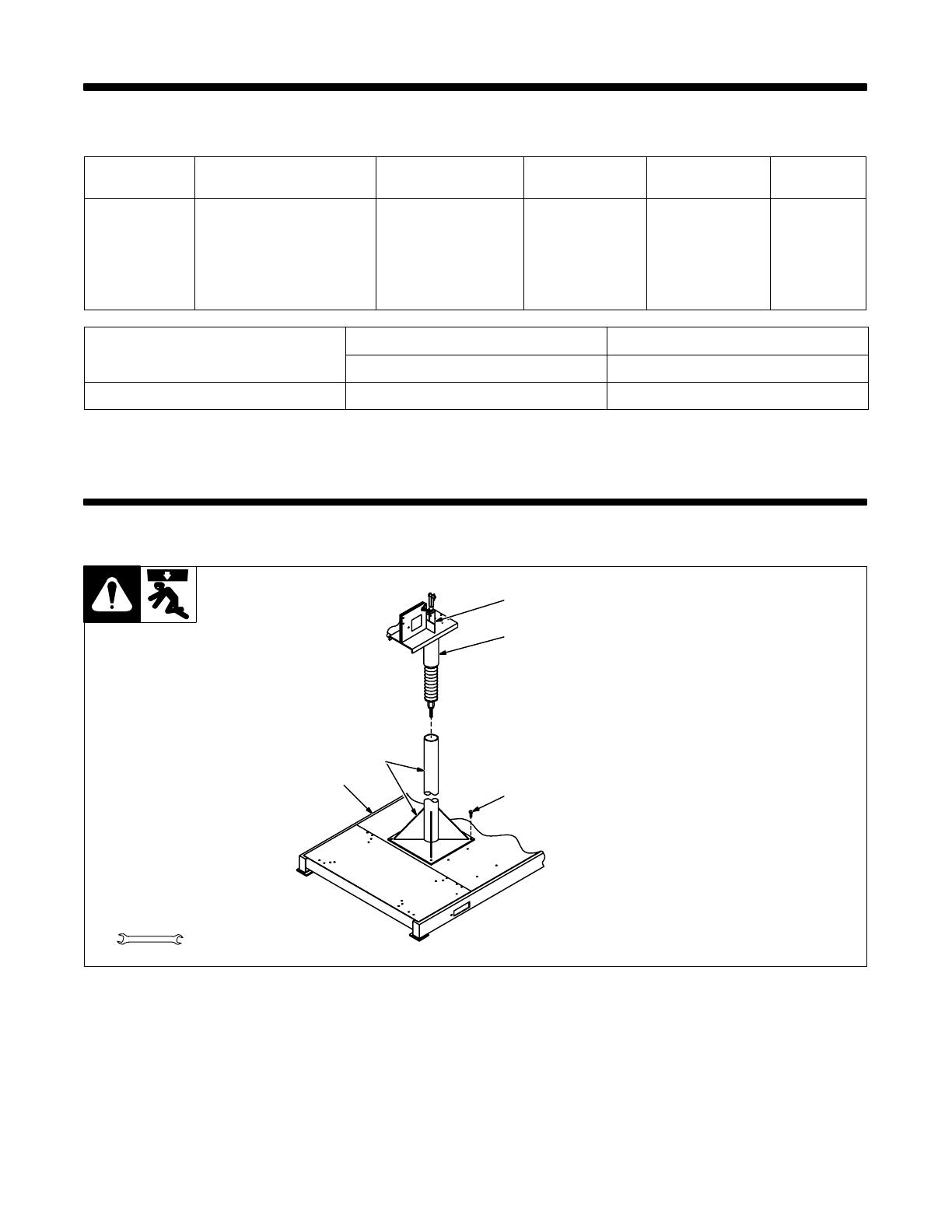
4-1. Installing Swivel Into Pipe Post
ST-152 382
1 Swingpak Base or CBC Cart
2 Pipe Post With Base
3 Steel Bolt
Secure as shown using as a mini-
mum 1/2 in diameter SAE grade 5
steel bolts.
4 Swivel Assembly
Insert into pipe post. Lubricate
swivel.
5 Safety Collar
Y Do not remove until
instructed to.
Tools Needed:
1
2
3
4
5
3/4 in
OM-1588 Page 10
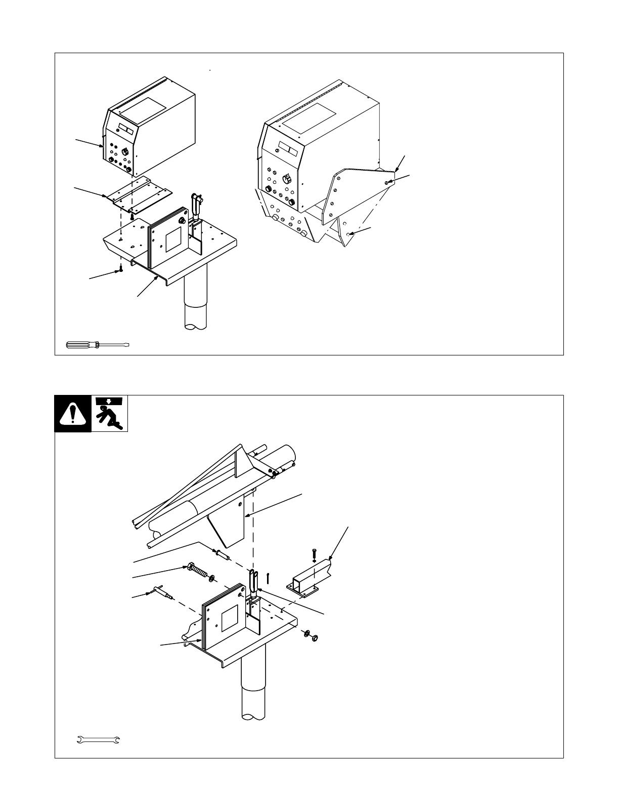
4-2. Installing Control Box And Adjusting Tilt
ST-800 174 / ST-801 278
1 Weld Control
2 Bracket
3 Screw
Bracket and screws are installed
onto bottom of control at factory.
4 Swivel
Loosen screws. Place control on
swivel and slide forward. Tighten
screws.
5 Tilt Bracket
6 Rear Pivot Screw
7 Front Screw
Loosen rear pivot screw. Remove
front screw. Pivot control down-
ward to desired viewing angle. Re-
place and tighten front screw. Tight-
en pivot screw.
Tools Needed:
5
6
7
1
2
3
4
4-3. Installing Boom And Reel Support
ST-153 170
1 Swivel Plates
2 Yoke
Remove hardware from swivel
plates and yoke.
3 Boom
Set boom into swivel as shown.
4 Yoke Pin
Install pin through yoke. Install cot-
ter pin and spread ends.
5 Bolt
Install bolt, washers, and nut. Tight-
en hardware, and back bolt off one
half turn.
6 Locking Knob
Install locking knob but do not
tighten.
7 Reel Support
Install reel support.
Tools Needed:
3/8, 3/4 in
3
4
5
6
7
1
2

OM-1588 Page 11
4-4. Installing Wire Guide Extension
ST-152 383
1 Wire Guide Fitting
2 Bolt
3 Monocoil Liner
4 Wire Guide Extension
Tighten bolt to secure liner in wire
guide fitting. Do not overtighten bolt
and crush liner.
Repeat procedure for opposite
side.
Tools Needed:
1
2
3
4
3/8 in

OM-1588 Page 12
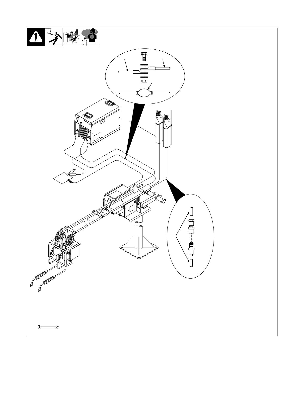
4-5. Equipment Connection Diagram
ST-801 806 / Ref. ST-175 086 / Ref. ST-180 311-B
1 300/400 Ampere Model
CC/CV Inverter Welding
Power Source
. Use settings shown for both
pulse MIG welding and MIG
welding.
2 450 Ampere Model CV
Inverter Welding Power
Source
3 14-Pin Cord
4 Positive (+) Weld Cable
5 Negative (−) Weld Cable
Be sure weld cables are sized prop-
erly for peak amperage if pulse
welding (see welding power source
Owner’s Manual).
6 Workpiece
7 Voltage Sensing Lead
(Optional Use)
8 Gun
Be sure gun is rated for peak am-
perage if pulse welding. Install ac-
cording to its Owner’s Manual.
9 Wire Feeder
For connections see Section 4-7.
10 Shielding Gas Supply
11 Supplied Y Adapter
12 Gas Hose From Boom
3
4
5
6
7
8
9
2
12 12
11
10
1
OM-1588 Page 13
4-6. Connecting Weld Cables And Gas Hoses
Ref. ST-801 806 / Ref. ST-152 800-A
Tools Needed:
5/8 in
The weld cables and shielding gas
hoses extend 10 ft (3 m) from the
boom.
Route weld cables from boom
through reed relays, if applicable.
If the welding power source or gas
supply are further from the boom,
extend cables or hoses as follows:
1 Weld Cable
2 Insulated Sleeving
Bolt together weld cables from
welding power source and boom.
Use electrical tape and insulated
sleeving to cover connection.
3 Shielding Gas Hose
Connect hose to gas supply or ex-
tension hose. The hose from the
boom has 5/8-18 right-hand
threads.
11
2
3
Gas Supply
Boom

OM-1588 Page 14
4-7. Control Box Connections
ST-800 177-A / Ref. ST-800 175
1 Optional Reed Relay
Connection
2 Wire Feed Motor And Gas
Valve Control Receptacle
3 Wire Feed Motor And Gas
Valve Control Plug From
Boom
4 14-Pin Cord
5 Volt Sense Lead (Optional
Use)
6 Gun Trigger Plug From Boom
4
1
5
3
2
2
6
4-8. 14-Pin Plug Information
Pin* Pin Information
A 24 volts ac with respect to socket G.
B Contact closure to A completes 24 volts ac contactor control circuit.
AJ
G Circuit common for 24 volts AC circuit.
AJ
B
K
I
C +10 volts dc output to remote control with respect to socket D.
C
L
NH
D
M
G
D Remote control circuit common.
D
M
G
E
F
E 0 to +10 volts dc input command signal from remote control with respect to socket D.
E
F
H Voltage feedback; 0 to +10 volts dc, 1 volt per 10 arc volts.
F Current feedback; 0 to +10 volts dc, 1 volt per 100 amperes.
M CC/CV Select (+24 V = CV)
N Inductance (0-10 V)
*The remaining pins are not used.
OM-1588 Page 15
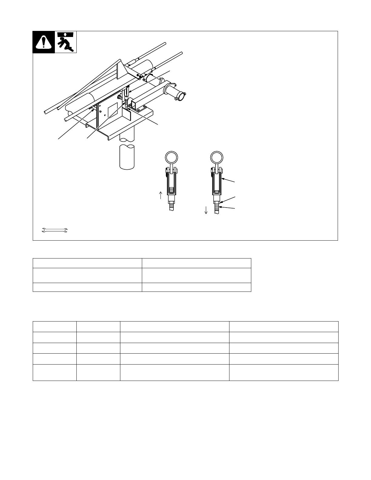
4-9. Removing Safety Collar And Adjusting Boom
ST-142 599-B
1 Locking Knob
Tighten knob to prevent boom
movement. Loosen knob to allow
boom movement. Change knob po-
sition to limit upward movement.
Pull boom down slightly and re-
move safety collar. Boom should
balance in any position from hori-
zontal to 60 degrees above hori-
zontal. If necessary, adjust boom
as follows:
2 Threaded Rod
3 Jam Nut
Loosen jam nut and turn threaded
rod until boom balances. Tighten
jam nut. Be sure several full threads
are through yoke to prevent boom
falling.
4 Yoke
Retain safety collar for use in disas-
sembling or moving boom.
1
2
4
3
2
3
4
Rod
Rod
Increasing Spring
Pressure For A Heavy
Gun
Decreasing Spring
Pressure For A
Lighter Gun
Tools Needed:
1-1/8 in
4-10. Gun Recommendation Table
Process Gun
GMAW − Hard or Cored Wires Roughneck C-Series Guns: 300, 400, 500, And
600 Amp.
FCAW − Self-Shielding Wires FC-1260 Or FC-1150
4-11. Wire Type, Size, And Feed Speed Capability Table
Motor Speed Wire Type Wire Size Feed Speed Capability
Standard All .023 To 5/64 in (0.6 To 2 mm) 50 To 780 ipm (1.3 To 19.8 mpm)
Standard All 3/32 To 7/64 in (2.4 To 2.8 mm) 50 To 700 ipm (1.3 To 17.8 mpm)
Standard All 1/8 in (3.2 mm) 50 To 300 ipm (1.3 To 7.6 mpm)
Optional High
Speed
All .023 To 5/64 in (0.6 To 2 mm) 92 To 1440 ipm (2.3 To 35.6 mpm)

OM-1588 Page 16
4-12. Installing And Threading Welding Wire
Install wire spool. Ad-
just tension nut so
wire is taut when wire
feed stops.
Install wire guide.
Pressure
Indicator
Scale
Pressure
Adjust
Install drive rolls.
NONCONDUCTIVE
SURFACE
NONCONDUCTIVE
SURFACE
No Wire Slip Wire Slips
ST-152 564-B / Ref. ST-156 929 / Ref. SC-150 922 / Ref. ST-156 930 / S-0627-A
. Be sure that outlet cable has proper size
liner for the welding wire size. When
installing gun, position liner extending
from outlet wire guide as close as pos-
sible to drive rolls without touching.
Install gun. Lay gun cable out straight. Cut off
end of wire. Push wire through guides up to
drive rolls; continue to hold wire. Press Jog
button to feed wire out gun.
. For soft wire or small diameter stainless
steel wire, use 2 drive rolls and set drive
roll pressure from 0 to a maximum of 4
on the pressure indicator scale (so that
only the inner spring is compressed).
This setting will generally give the best
performance for these types of wires.
To adjust drive roll pressure, hold nozzle
about 2 in (51 mm) from nonconductive
surface and press gun trigger to feed wire
against surface. Tighten knob so wire does
not slip. Do not overtighten. If contact tip is
completely blocked, wire should slip at the
feeder (see pressure adjustment above).
Cut wire off. Close cover.
Repeat for other side.
Tools Needed:
3/16, 5/64 in
15/16, 3/8 in

OM-1588 Page 17
SECTION 5 − OPERATION
5-1. Operational Terms
See Menu Guide for detailed programming steps.
Note
The following is a list of terms and their definitions as they apply to this wire feeder:
General Terms:
Adaptive Pulse Welding The wire feeder automatically regulates pulse frequency to maintain a constant arc length, regardless
of change in welding wire stickout.
Cold Wire Jog When weld amperage is not present, wire feeds for about three seconds at set wire feed speed. Then
the welding power source contactor deenergizes and wire continues to feed at the wire jog speed.
Inductance As inductance increases, arc on time increases, and the weld puddle becomes more fluid.
SharpArc™ Arc cone width and arc characteristics adjustment in pulse welding. Increasing SharpArc value de-
creases the arc cone width.
Trim Arc length adjustment in pulse welding. Increasing trim increases the actual arc length. Trim is re-
placed by volts in MIG programs.
Synergic The operator programs pulse parameters for a specific wire feed speed. The wire feeder determines
the pulse parameters between these wire feed speed increments.
Side Panel Terms:
Process Mode Is used to select the type of process to be used, including Pulse, Adaptive Pulse, or Mig.
Sequence Mode Is used to select and program the weld sequences which include weld, crater, burnback, postflow,
preflow, run-in, and start.
Dual Schedule Mode Is used to select a pair of programs that can be used together.
Card Mode Is used to select use of the optional data card storage and retrieval capabilities.
Security Mode Only functions with an optional data card. Allows using the lock feature for restricting range of pro-
gram parameter changing.
5-2. Pulse Welding Terms
1 Apk = Peak Amperage
Increasing Apk increases penetra-
tion.
Vpk = Peak Voltage
Arc voltage during peak current
phase of the pulse waveform. This
determines arc length during
adaptive pulse welding.
2 Abk = Background Amperage
Maintains arc between pulses.
3 PPS = Pulses Per Second
Increasing PPS increases travel
speed.
4 PWms = Pulse Width In
Milliseconds
Increasing PWms increases bead
width.
Time
Amps
3
1
2
4
OM-1588 Page 18
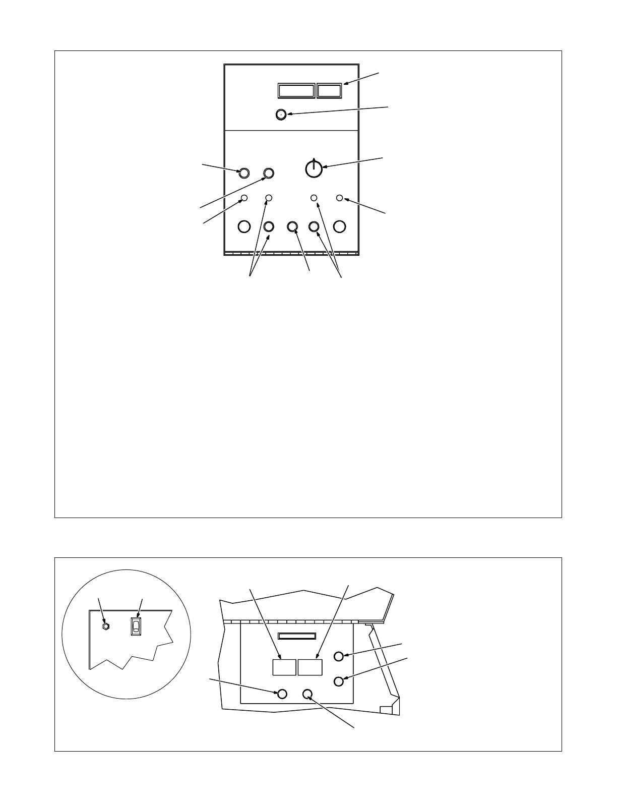
5-3. Front Panel Controls
ST-162 127
1 Display
2 Parameter Select Button
Press button to move > (the cursor) on the
display.
3 Display Control
Turn control to change value pointed to by >.
Turning control one click causes Trim (arc
length) to increase/decrease by one or Volts
to increase/decrease by 0.1.
When IPM is selected, turning control one
click causes wire feed speed (IPM) to in-
crease/decrease by one.
When MPM is selected, turning control three
clicks causes wire feed speed (MPM) to in-
crease by 0.1.
When Prg # is selected, turning control one
click causes program number (Prg #) to in-
crease/decrease by one.
The program number cannot be changed
while welding, with exception of Dual Sched-
ule Mode (see Section 7).
SharpArc™ is “Arc” on the display (see Sec-
tion 12). It is used to adjust arc cone width and
arc characteristics.
Pulse is a default setting. To change type of
process (Pulse, Adaptive Pulse, or MIG) use
side panel controls (see Section 5-4).
4 Active Side Indicator Light
5 Trigger Hold Button And Indicator Light
Trigger Hold can be set on a per program ba-
sis. Indicator light comes on for programs
where this feature is active.
To weld without holding gun trigger through-
out weld cycle, press and release button to
turn feature on (indicator light turns on).
To start weld cycle, press and release gun
trigger within three seconds after an arc has
been struck. To end weld cycle, press and re-
lease gun trigger.
6 Side Select Button
The feeder remembers the last used program
for each side and returns to that program
when the active side is changed.
. The gun trigger may be used to change
active side of the feeder.
7 Jog Button
Push to momentarily feed welding wire with-
out energizing welding circuit or shielding gas
valve.
Jog speed is varied using the Display Control
while Jog button is pressed. Default setting is
200 IPM.
8 Purge Button
Push to momentarily energize gas valve with-
out energizing the welding circuit.
. Jog and Purge only work on the active
side of the feeder.
Holding the Jog and Purge buttons at the
same time displays pulse parameters on
the side panel display and voltage on front
panel display.
1
2
3
4
5
6
5
4
7
8
5-4. Side And Rear Panel Controls
Ref. ST-162 128 / Ref. ST-162 133
1 Mode Display
2 Mode Select Button
Press button to move > in display.
3 Parameter Display
4 Parameter Select Button
Press button to move > in display.
5 Parameter Increase Button
6 Parameter Decrease Button
7 Power Switch
8 Circuit Breaker CB1
CB1 protects the wire feeder from
overload.
Rear Panel
8 7
5
1
2
6
4
3
OM-1588 Page 19
SECTION 6 − SETTING SEQUENCE PARAMETERS
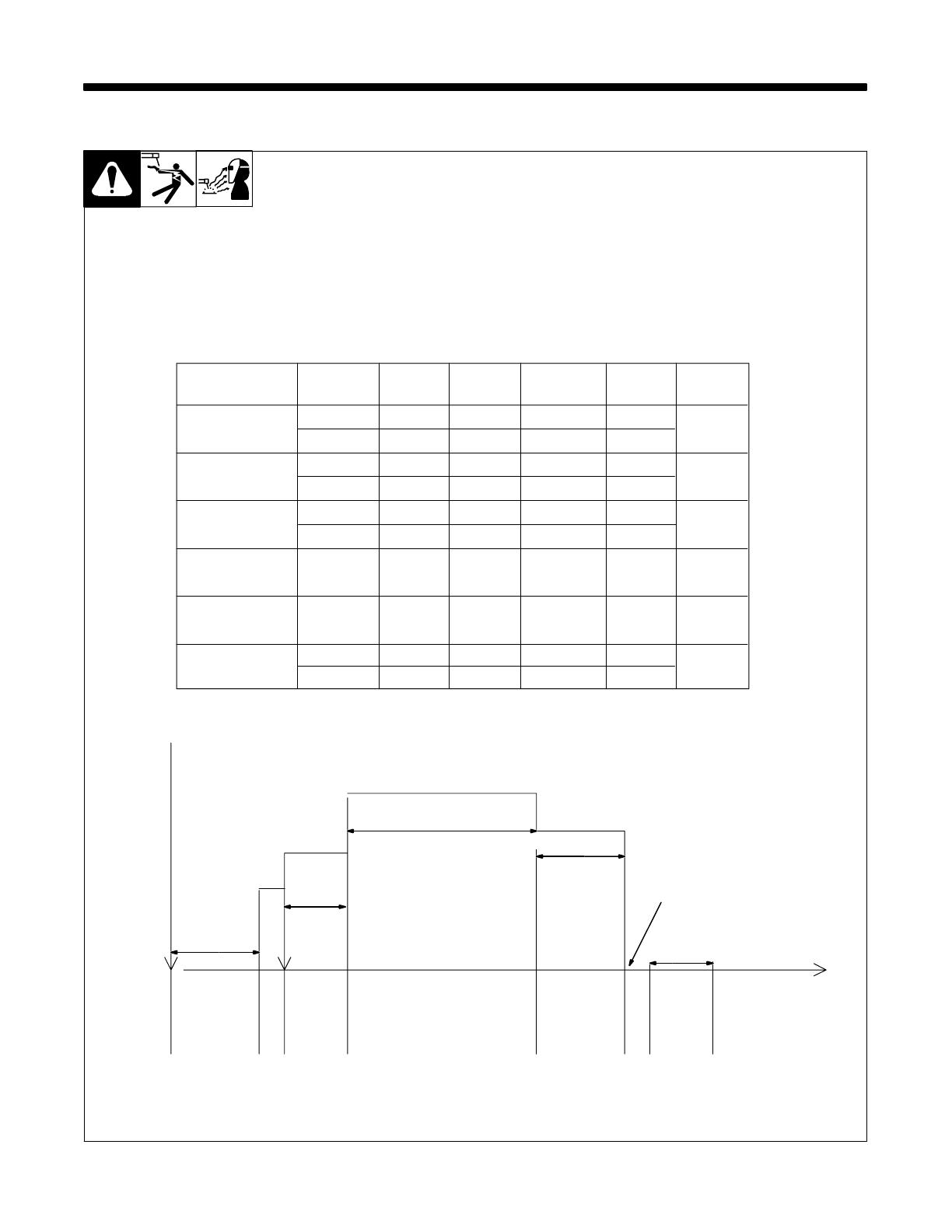
6-1. Sequence Parameters In A Program
. See Menu Guide for detailed
programming steps.
Trim is arc length. If set to zero, arc
length is short. If set to 99, arc
length is long.
If time is set to zero in Weld
sequence, welding continues until
gun trigger is released.
If time is set to zero in any timed
sequence except Weld, the
sequence is skipped.
Trigger
Pressed
Trigger
Released
Wire Speed
Time
Start
Time
Preflow
Run-In WFS
Weld WFS
Weld Time
Crater WFS
Crater
Time
Postflow
Arc
Strike
Burnback
Time
Time
Time
PostflowCrater
WeldRun-In
Preflow
Burnback
Sequence
End
Trim
0-99
Volts
10.0-38.0
Inductance
0-99%
IPM
50-780
Seconds
1. Weld
2. Crater
3. Burnback
4. & 5. Postflow/
Preflow
6. Run-In
Pulse
MIG
Pulse
MIG
MIG
0-100.0
0-5.00
0-0.25
0-9.9
X
XX X
X
XX
X
25-780
X
X
X = Setting available.
Pulse
6. Start
Pulse
MIG
0.00-5.00XX
XX
0-100 sec.
/