Page is loading ...

Frameless
3/8” Glass
Shower
Door
COPA00A
the COPPIA SINGLE SWING
BECAUSE THE SHOWER IS EVERYTHING
www.BascoShowerDoor.com | 800.45.BASCO
QCI5298

QCI5298 REV. 0 Page 2 Cered 10/1/17
Installation Notes:
This unit may be installed on a walls without proper blocking, including fiberglass and acrylic
walls. Proper use of the described anchors and silicone is required.
If blocking is available for installation, DO NOT use wall inserts. Screw directly into the wood-
en blocking.
U-Channel may be installed using wall plugs where no backing is found.
Use caution to not pierce plumbing or electric lines while installing door hardware.
Cover the drain with tape prior to installation to prevent loss of small parts.
Unpack your unit carefully and inspect for freight damage. Lay out and identify all parts using
the instruction sheet as a reference. Before discarding the carton, check to see that no small
hardware parts have fallen to the bottom of the box. If any parts are damaged or missing, refer
to the description noted in the instructions when contacting your dealer for replacements.
Tools:
To install your RODA Shower Enclosure, you may need the following:
Pencil
Low Tack Tape
Tape Measure
2’, & 4’ Levels
#2 Phillips Screwdriver
Hack Saw
Caulk Gun
Clear Silicone Caulk
Suction Cups
7/16” shims
Drill
1/8”, 5/32”, 3/16”, 5/16”
Metal Drill Bits
3/16” or 5/16” maybe required
in some installations
Center Punch
Files
This unit is best installed by two people.
Handle the glass panels carefully and protect the edges. Safety tempered glass is very re-
sistant to breakage, but the sharp corners of the panels can damage tile, flooring surfaces,
and easily damaged at the corners.
The glass can break if unequal pressure is applied during installation.
Please wear safety glasses whenever drilling or cutting. When drilling holes in ceramic tile or
marble, use a center punch and hammer to carefully break the glazed surface to prevent skid-
ding when drilling.
NOTE: Tempered glass cannot be cut.
Safety Notes:

QCI5298 REV. 0 Page 3 Cered 10/1/17
Maintenance:
Two primary materials are used to manufacture your new Basco shower enclosure: tempered
glass and anodized aluminum. To assure a long lasting finish on the enclosure, wipe it down with
a towel after each use.
For occasional, more concentrated cleaning efforts, we find that Lysol® Non-Abrasive Bath-
room Cleaner works extremely well. Be sure that any over spray falling on the aluminum frame is
rinsed thoroughly and dried. Many over-the-counter cleaners, if applied to the aluminum and left
on, will harm the metal finish and cause permanent damage even though their directions indicate
safe use on shower doors. Never use a scouring agent to clean the aluminum.
For units with AquaglideXP Basco recommends the use of Maintain Spray on the glass. Please
contact customer service for details.
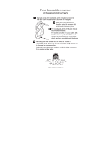
This unit is completely reversible and may be installed hinge-right or hinge-left. Refer to the illustra-
tion to determine the best position of the hinge for your installation. For maximum water proofing,
the hinge jamb should always be opposite the shower head.
Orientation Note:
CAUTION: For safety purposes, the door MUST ALWAYS open outward.

QCI5298 REV. 0 Page 4 Cered 10/1/17
Adjustable Door Parts View
1
9
12
8
13
6
7
3
5
2
4
8
11
10
15
14
16

QCI5298 REV. 0 Page 5 Cered 10/1/17
Adjustable Door Parts List
ITEM NO. Part # DESCRIPTION QTY
1 GLASS DOOR 1
2 SC982 Hinge Jamb 1
3 SC983 Adjustable Hinge Jamb 1
4 SC508 Wall Jamb 1
5 SC552 Adjustable Strike Jamb 1
6 SCV920 Drip Vinyl 1
7 SCV266 Strike Vinyl 1
8 HG1J Wall Mount Hinge 2
9 PU1D Back to Back Pull 1
PPHVY03XX Heavy Adjustable Unit PartsPak 1
10 SCR10 #8 x 1 1/2” Truss Head Screw 10
11 SCR28 #8 x 1/2” Threading Truss Head Screw 6
12 SCR29 #8 x 1/2” Threading Flat Head Screw 8
13 SCR24 #6 x 3/8” Self Tapping Screw 2
14 SCR09 #8 x 1 1/2” Flat Head Screw 8
15 SC4106 Blue Wall Anchor 8
16 TA Anchor TA Wall Anchors 8
- TKRED Wall Anchor Key 1
-
Alcohol Pad 3
-
1/16” Setting Blocks 8
-
1/8” Setting Blocks 8
-
1/4” Setting Blocks 2
Note: You will not use every part in the PartsPak. Some extra hardware is provided for your convenience. The PartPak
is used on multiple style doors which may use other parts than required for your installation.

QCI5298 REV. 0 Page 6 Cered 10/1/17
Lightly mark a continuous unit centerline on the
threshold.
Next, mark a continuous unit centerline up each wall,
starting where the threshold centerline meets the wall.
Use a level to ensure the wall centerline is plumb and
straight. The wall centerlines should be a minimum of
the unit height from the threshold.
Note: It is extremely important the unit cen-
terline be continuous and straight to ensure
proper installation.
On the wall selected for installation of the door, check the fit of SC982 Hinge Jamb [2] where
the threshold and wall meet. In many cases the corner will need to be contoured to fit a radius.
Contour the corner as required to ensure proper contact with the wall and threshold.
Proper fit in this area allows the door to be installed on a fiberglass enclosure or walls
with no blocking. Failure to radius the corner for proper fit may cause the door to fall
causing property damage and bodily harm.
Note: It is imperative that SC982 rest on the threshold. Out-of-Level conditions may dictate the
door and SC983 jamb assembly be raised such that SC983 does not contact the threshold. This
installation is permitted, but is to be avoided if possible.
Centerline (CL) is a term used to describe the center or mid-point of the unit. The most common unit
centerline position is the middle of the threshold. CL is marked in when visible in images.
1
2
NO!
NO!
YES!
YES!

QCI5298 REV. 0 Page 7 Cered 10/1/17
Place the SC982 Wall Jamb [2] on the wall. Using
a level, line the center of the wall jamb up with the
centerline marked in step 1 and make it plumb.
Mark the 8 holes (4 at each hinge) on the wall for
securing.
The centerline should run through the center holes.
NOTE: The customer may move the location of the
mounting screws up or down 3”. The customer is
responsible for drilling new holes at the required
location. All 4 holes are required to be used. The
diamond pattern is also required.
4
3
Remove the Wall Jamb [2] and drill holes for mounting screws as required. See Table 1 for
drilling details.
Table 1 - Mounting Hole Drilling Requirements
Wall Material
Any Fiberglass Tile/Other
Blocking Available In Wall YES NO NO
Finish Material Drill Diameter 3/16" 5/16" 5/16"
Blocking Drill Diameter 1/8" Not Applicable Not Applicable
Insert Required NONE Included Customer Provided
1
Total Wall Thickness All
2
¼" or less Over ¼"
2
1) Basco includes the required Toggler® brand wall plugs for installation on a fiberglass or
acrylic shower unit. If your installation surface is different the customer maybe required to
provide your own mounting hardware. Use only Toggler® brand wall plugs. Find the part
number required for your wall thickness in Table 2. These are available for purchase at
Lowe’s® and Menards®.
2) If finished wall material is over 3/4” the cus-
tomer will be required to provide their own
mounting screw. Basco recommends #8x3”
stainless steel truss head screws for fin-
ished wall material over 3/4”.
3) If wall material thickness is between thick-
nesses and require inserts use the insert
for the thinner size
Table 2 - Wall Inserts
Wall
Thickness
3
Part Number
Toggler® Lowe's® Menards®
1/8" to 1/4" TA
50275 INCLUDED
3/8" to 1/2" TB
50300 114767 2344078
5/8" to 3/4" TC
50325 114823 2344065
CL

QCI5298 REV. 0 Page 8 Cered 10/1/17
5
Drill 5/16” diameter holes at each marked location.
Install 1 TOGGLER® per hole following the manufacturers’ installation instructions.
Fold anchor in middle
Insert anchor in hole and tap
flush
At each marked location, drill a 3/16” clearance hole through the
finished wall material only.
Drill a 1/8” diameter pilot hole 1” deep into the blocking at the
marked locations.
IF BLOCKING IS AVAILABLE IN THE WALL
6
IF WALL ANCHORS ARE REQUIRED FOR INSTALLATION
CL
Insert key to pop anchor open in
wall.
Do not hammer key.
Remove key.

QCI5298 REV. 0 Page 9 Cered 10/1/17
7
Using alcohol swabs from the Parts Pak, thoroughly clean and dry the area of the wall where
jamb will be installed on. Also clean and dry the back of the Wall Jamb [2]
Apply a continuous 3/16” to 1/4” bead of silicone inside each leg of the Wall Jamb [2] where
it meets the wall. The silicone should protrude past the leg it will contact the wall and spread
out when Wall Jamb [2] is secured in place.
WALL
WALL
3/16” to 1/4” silicone bead
3/16” to 1/4” silicone bead
Wall Jamb secured to wall
3/16” to 1/4” silicone bead
Place a small amount of silicone in each screw hole.
Use a level again to make sure the wall jamb in installed plumb and in its final position.
Using, #8 Truss Head Screw [10] secure the SC982 Wall Jamb [3] to the wall.
If using power tools to install screws: Use caution so as to not strip the insert or backing, as ap-
plicable.
Clean up any visible silicone before it dries.
8

QCI5298 REV. 0 Page 10 Cered 10/1/17
On the wall selected for installation of the strike jamb, check the fit of SC508 and SC552 [4,5]
where the threshold and wall meet. In many cases the corner will need to be contoured to fit a
radius.
Contour the corner as required to ensure proper contact with the wall and threshold.
Proper fit in this area allows the door to be installed on a fiberglass enclosure.
9
NO!
NO!
YES!
YES!
4”
Wall hidden
for clarity
Drill 3 3/16” diameter holes along the
centerline of the SC508 Wall Jamb [4].
Place 1 hole in the center and 1 hole 4” from
each end.
10

QCI5298 REV. 0 Page 11 Cered 10/1/17
Remove the jamb from the wall. At each marked location, drill for installation of the jamb. Use
Table 3 to determine hole size and installation method for the strike jamb
12
Align the Wall Jamb [4] along the
centerline marked up the strike side
wall.
Use a level to ensure the wall jamb is plumb.
Mark the hole locations on the wall.
11
Table 3 - Mounting Hole Drilling Requirements
Wall Material
Fiberglass or Acrylic Fiberglass or Acrylic Tile/Other
Reinforced Walls YES NO -
Drill Diameter 1/8" 1/8" 3/16"
Insert Required NO No Yes, Blue Insert
CL
13
Insert a small amount of silicone into each
drilled hole.
If applicable, insert a blue wall plug into
the hole. Carefully cut the head flush with
the wall using a razor blade.
Position the u-channel and secure with #8
Flat Head Screws [14].
Use caution so as to not strip the in-
serts or fiberglass wall material!
Wall hidden
for clarity

QCI5298 REV. 0 Page 12 Cered 10/1/17
Using alcohol pads from the Parts Pak, wipe down
the hinge notches and notch gasket areas on the
Door Panel Glass [1]. Allow glass to dry before
continuing.
Remove the back plates from both HG1J Hinges [8].
Place a thick gasket on the Hinge [8] and place the fixed
part of hinge onto the outside of the Door Glass [1].
Next, place another thick gasket against the inside of the
glass and attach the back plate with the screws provided.
The interior of hinges must press firmly against top side
of notch.
Using a screw driver, use 8 hinge mounting screws [12] to attach both HG1J Hinges [8] to
SC982 Adjustable Jamb [3].
Hinge Mounting Screw [12] are self threading screws. The mounting holes, while pre-drilled, are
not tapped by Basco. The screws will go in easily using a standard screw driver. If power tools are
used to insert the screws, use caution so as to not strip the metal.
Loosen the screws from step 8 and adjust as required to achieve a 1/4” gap between the Glass and
Jamb.
Be sure to tighten these screws again.
15
14
As viewed from inside of shower

QCI5298 REV. 0 Page 13 Cered 10/1/17
Place two 7/16” shims on the curb or threshold. These shims must remain in place throughout
the installation process. You can stack setting blocks from the Parts Pak if required.
With the help of an assistant inside the shower, lift the Door Glass Assembly into the opening and
set the panel on the shims. Slide the Adjustable Wall Jamb [3] over the Hinge Wall Jamb [2].
Work together to make the door plumb and level, adding or removing shimming from under the door
as required.
16
After the door is leveled, push or pull the door assembly as required to set the gap between
the Glass [1] and the Strike Wall Jamb [4]. Check the top and bottom of the door for the gap.
Set the gap at between 1/4” and 13/16”.
The strike and jambs allows for out of plumb adjustment in the wall as well as some width adjust-
ment. The gap may not be consistent the entire unit height.
CL
7/16” Shim
7/16” Shim
SLIDE ONTO WALL JAMB
17
1/4” to 13/16” GAP
TOP AND BOTTOM
Strike
Wall Jamb
Door Edge
LEVEL

QCI5298 REV. 0 Page 14 Cered 10/1/17
While keeping the door level, plumb, and with the correct gap at the strike side; drill 5/32”
holes through the SC982 Wall Jamb [2] at the locations marked by the holes near each hinge
in SC983 Adjustable Jamb [3]. The holes are on the side of the jamb, both inside and out-
side of the shower.
18
Insert Hinge Jamb Screws [11] into each hole drilled in step 18.
The screws will go in easily using a standard screw driver. If power tools are used to insert the
screws, use caution so as to not strip the metal.
19
CL
DO NOT open the door until the
both Hinge Jamb Screws [11] are
installed on the inside or outside
of the shower. There is nothing
securing the door to the wall unit
these screws are installed. The
door WILL fall.
Once both screws are installed the
door may be carefully temporarily
opened to allow access to the other
side of the door for installation of the
Hinge Jamb Screws [11].

QCI5298 REV. 0 Page 15 Cered 10/1/17
After all 4 Hinge Jambs Screws [11]
are installed, remove the 7/16” shims
and carefully open the door, making
sure the glass does not contact anything.
Slowly open and close the door to ensure
the hinges are in alignment and are operat-
ing smoothly.
20
Slide the SCV266 Strike Vinyl [7] into the Strike Jamb [5].
21
CL

QCI5298 REV. 0 Page 16 Cered 10/1/17
Slide the SC552 Strike Jamb [5] over the
SC508 Wall Jamb [4]. Fully compress the
jambs.
Make sure the strike jamb is placed to allow the
door to close against the vinyl.
22
CL
CL
CL
Close the door against the SC552 Strike Jamb [5].Slide the SC552 Strike Jamb [5] over to-
wards the door, leaving a consistent 3/16” gap between the glass and the jamb.
The jamb is designed to adjust for any out of plumb conditions the wall may have. This may make
for an uneven reveal of the SC508 wall jamb [4].
23
3/16”
INSIDE Shower
OUTSIDE Shower

QCI5298 REV. 0 Page 17 Cered 10/1/17
From INSIDE SHOWER drill 2 1/8” diameter holes through the inside wall of the Strike and
Wall Jambs.
Locate the hole 1.5” from the top and bottom edges of the jamb, 3/4” from the wall.
24
Insert screw SCR24 [13] into each hole to secure the strike jamb into position.
3/4”
1 1/2”
CL
To prevent the door from sagging after final
gap adjustment the hinge maybe shimmed
to prevent movement.
Remove one back plate at a time and fill gaps
(marked in the figure to the left) surrounding hinge
with shims supplied in parts pack. Make sure to
shim both hinges and use combination of shim
thicknesses to fill entire gap.
25

QCI5298 REV. 0 Page 18 Cered 10/1/17
Assemble parts as shown. Screw washers, end plates, and gaskets into one side of the han-
dle through the glass. Then align the other side of the handle onto the bushing and tighten the
set screws. The screw head should be inside the shower.
26
Handle Installation

QCI5298 REV. 0 Page 19 Cered 10/1/17
Place the Drip Vinyl onto the bottom of the door
panel. Line it up on the hinge side of the door
and cut it off flush with beginning of the Strike
Jamb.
Once adjusted to fit, run a small bead of silicone be-
tween the drip vinyl and the glass to secure the vinyl
sweep and prevent water from collecting inside the
sweep if adjusted.
27
Inside the shower, carefully run a continuous bead of silicone between the wall an SC508
Wall Jamb [4] on the strike side. Apply another bead of silicone around where the jambs
meet the threshold.
It is optional to also run a bead between the wall jamb and the wall on the outside of the shower.
28

QCI5298 REV. 0 Page 20 Cered 10/1/17
Inside the shower, carefully run a continuous bead of silicone where SC982 Wall Jamb [2]
and SC983 Hinge Jamb [3] meet. Apply another continuous bead of silicone where the jamb
and wall meet. Apply a final bead where the jambs and threshold meet.
It is option to also run a bead between the jamb and wall on the outside of the shower.
29
DO NOT use the shower before the silicone has cured!
Follow the manufacturers’ recommendation for cure time (usually 24-
48 hours) before using the shower.
/