Thermador PODC302J Installation guide
- Category
- Microwaves
- Type
- Installation guide
This manual is also suitable for

INSTALLATION MANUAL
Built-in Ovens
Models:
M301
ME271
ME301
ME302
MED272
MED302
MEMC301
MEMCW271
MEMCW301
POD301
PODC302
PODM301
PODMW301

Table of Contents
Questions?
1-800-735-4328
www.thermador.com
We look forward to hearing from you!
This Thermador Appliance is made by
BSH Home Appliances Corporation
5551 McFadden Ave.
Huntington Beach, CA 92649
Safety . . . . . . . . . . . . . . . . . . . . . . . . . . . . . . . . . . . . . . . . . . . . . . . . . . . . . . . 1
Important Safety Instructions . . . . . . . . . . . . . . . . . . . . . . . . . . . . . . . . . . . . . 1
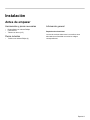
Preparation . . . . . . . . . . . . . . . . . . . . . . . . . . . . . . . . . . . . . . . . . . . . . . . . . . 2
Before you Begin . . . . . . . . . . . . . . . . . . . . . . . . . . . . . . . . . . . . . . . . . . . . . . . 2
Tools and Parts Needed . . . . . . . . . . . . . . . . . . . . . . . . . . . . . . . . . . . . . . . . . . . . . . . . . . . . . . 2
Parts Included . . . . . . . . . . . . . . . . . . . . . . . . . . . . . . . . . . . . . . . . . . . . . . . . . . . . . . . . . . . . . . 2
General Information . . . . . . . . . . . . . . . . . . . . . . . . . . . . . . . . . . . . . . . . . . . . . . . . . . . . . . . . . . 2
Dimensions for 27” Wall-Mounted Units . . . . . . . . . . . . . . . . . . . . . . . . . . . . . 3
Dimensions for 27” under the counter . . . . . . . . . . . . . . . . . . . . . . . . . . . . . . . . . . . . . . . . . . . . 4
Dimensions for 30” Wall-Mounted Units . . . . . . . . . . . . . . . . . . . . . . . . . . . . . 6
Dimensions for 30” under the counter . . . . . . . . . . . . . . . . . . . . . . . . . . . . . . . . . . . . . . . . . . . . 8
Removing Packaging . . . . . . . . . . . . . . . . . . . . . . . . . . . . . . . . . . . . . . . . . . . . 9
For Convection Microwave Combination Units . . . . . . . . . . . . . . . . . . . . . . . . . . . . . . . . . . . . 10
Preparing Oven . . . . . . . . . . . . . . . . . . . . . . . . . . . . . . . . . . . . . . . . . . . . . . . . . . . . . . . . . . . . 10
Microwave Combination Units Adjustment Feature . . . . . . . . . . . . . . . . . . . . . . . . . . . . . . . . . 11
Installation . . . . . . . . . . . . . . . . . . . . . . . . . . . . . . . . . . . . . . . . . . . . . . . . . 12
Electrical Installation . . . . . . . . . . . . . . . . . . . . . . . . . . . . . . . . . . . . . . . . . . . 12
Oven Installation . . . . . . . . . . . . . . . . . . . . . . . . . . . . . . . . . . . . . . . . . . . . . . . 13
Testing Operation . . . . . . . . . . . . . . . . . . . . . . . . . . . . . . . . . . . . . . . . . . . . . . 14
Service . . . . . . . . . . . . . . . . . . . . . . . . . . . . . . . . . . . . . . . . . . . . . . . . . . . . . 14
Before Calling Service . . . . . . . . . . . . . . . . . . . . . . . . . . . . . . . . . . . . . . . . . . . . . . . . . . . . . . . 14

English 1
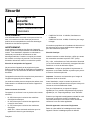
Safety
WARNING:
If the information in this manual is not followed exactly, fire
or shock may result causing property damage or personal
injury.
WARNING:
Do not repair or replace any part of the appliance unless
specifically recommended in the manuals. Improper
installation, service or maintenance can cause injury or
property damage. Refer to this manual for guidance. All
other servicing should be done by a qualified technician.
Appliance Handling Safety
Do not lift appliance by door handle. Remove the door for
easier handling and installation. See instructions in Use
and Care Manual.
Unit is heavy and requires at least two people or proper
equipment to move.
Hidden surfaces may have sharp edges. Use caution when
reaching behind or under appliance.
Safety Codes and Standards
This appliance complies with one or more of the following
Standards:
• UL 858, The Standard for the Safety of Household
Electric Ranges
• UL 923, The Standard for the Safety of Microwave
Cooking Appliances
• UL 507, The Standard for the Safety of Electric Fans
• ANSI Z21.1, The American National Standard for
Household Cooking Gas Appliances
• CAN/CSA-C22.2 No. 113-M1984 Fans and Ventilators
• CAN/CSA-C22.2 No. 61-M89 Household Cooking
Ranges
It is the responsibility of the owner and the installer to
determine if additional requirements and/or standards
apply to specific installations.
Electric Safety
Before you plug in an electrical cord, be sure all controls
are in the OFF position.
If required by the National Electrical Code (or Canadian
Electrical Code), this appliance must be installed on a
separate branch circuit.
Installer - show the owner the location of the circuit
breaker or fuse. Mark it for easy reference.
Important - Save these instructions for the local electrical
inspector's use.
Before installing, turn power OFF at the service panel. Lock
service panel to prevent power from being turned ON
accidentally.
Refer to data plate for more information. See "Data Plate"
under "Service" for data plate location.
Be sure your appliance is properly installed and grounded
by a qualified technician. Installation, electrical connections
and grounding must comply with all applicable codes.
Related Equipment Safety
Remove all tape and packaging before using the appliance.
Destroy the packaging after unpacking the appliance.
Never allow children to play with packaging material.
Never modify or alter the construction of the appliance. For
example, do not remove leveling legs, panels, wire covers
or anti-tip brackets/screws.
Important Safety
Instructions
READ AND SAVE THESE
INSTRUCTIONS

English 2
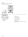
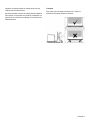
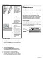
Transport
To avoid damage to the oven vent, use the transport
method shown in the picture below.
Preparation
Before you Begin
Tools and Parts Needed
• Phillips head screwdriver
• Measuring tape
• Drill with bit (1/8")
Parts Included
• Phillips head screws (6)
General Information
Power Requirements
The outlet must be properly grounded in accordance with
all applicable codes.

English 3
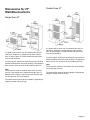
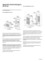
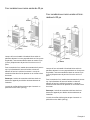
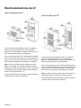
Dimensions for 27”
Wall-Mounted Units
Single Oven 27”
It is good practice, when oven is installed at the end of a
cabinet run, adjacent to a perpendicular wall or cabinet
door, to allow at least 1/4” space between the side of the
oven and the wall/door.
For oven support, install 2x4’s extending front to back flush
with the bottom and the side of the opening. The supporting
base must be well secured to the floor/cabinet and level.
Note:
The conduit box must be installed either above or below
the unit. If the conduit box is installed below the unit, a 2”
diameter hole or space is required between the back wall
and the right rear of the 2x4 supports.
The cabinet base must be flat and capable of supporting a
weight of at least 193 lbs (87 kg).
Double Oven 27”
It is good practice, when oven is installed at the end of a
cabinet run, adjacent to a perpendicular wall or cabinet
door, to allow at least 1/4” space between the side of the
oven and the wall/door.
For oven support, install 2x4’s extending front to back flush
with the bottom and the side of the opening. The supporting
base must be well secured to the floor/cabinet and level.
Note:
The conduit box must be located above the unit to facilitate
connecting and servicing.
The cabinet base must be flat and capable of supporting a
weight of at least 361 lbs (164 kg).
27 1/16”
(687mm)

English 4
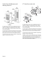
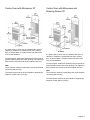
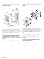
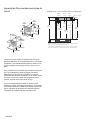
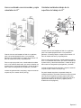
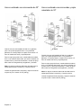
Combo Oven with Microwave and
Warming Drawer 27”
It is good practice, when oven is installed at the end of a
cabinet run, adjacent to a perpendicular wall or cabinet
door, to allow at least 1/4” space between the side of the
oven and the wall/door.
For oven support, install 2x4’s extending front to back flush
with the bottom and the side of the opening. The supporting
base must be well secured to the floor/cabinet and level.
The cabinet base must be flat and capable of supporting a
weight of at least 369 lbs (167 kg).
27” Under-the-counter units
It is good practice, when oven is installed at the end of a
cabinet run, adjacent to a perpendicular wall or cabinet
door, to allow at least 1/4” space between the side of the
oven and the wall/door.
For oven support, install 2x4’s extending front to back flush
with the bottom and the side of the opening. The supporting
base must be well secured to the floor/cabinet and level.
The cabinet base must be flat and capable of supporting a
weight of at least 193 lbs (87 kg).
This Built –In Oven can be installed below any Thermador
cook top as long as there is no contact between the bottom
of the cook top and the top of the oven, except for the
Thermador Induction cooktop, where the gap must be of at
least 1 inch (see illustrations on page 5).
36
"
(915mm
)
20
"
(508mm)
28
1/4"
(718mm)
16
1/2"
(419mm)
24
"
(610mm)
4
3/4"
(121mm)
25
1/2"
(648mm)
23
7/8"
(606mm)
22
"
(559mm)
29
1/16"
(738mm)
26
3/4"
(680mm)
24
13/16"
(630mm)
27 1/16”
(687mm)
min. 3
"
(76mm)

English 5
27
1
/16"
(687mm)
29
1
/16"
(738mm)
24
7
/16"
(621mm)
36"
(914mm)
SUMP
4
3
/16"
(106mm)
3
15
/16"
(99mm)
4
15
/16"
(125mm)
6
3
/4"
(172mm)
1
13
/16"
(47mm)
1
/4"
(7mm)
4
3
/4"
(121mm)
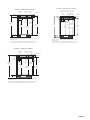
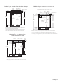
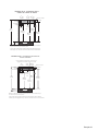
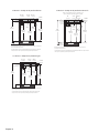
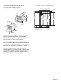
Note: Dimensions based on standard countertop height (36" with 4
3
/4" toe kick
including base plate).
The built-in oven can be installed below the electric cooktop as long as there is
no contact between the bottom of the cooktop and the top of the oven.
TOE KICK
COOKTOP
OVEN
TOE KICK
COUNTERTOP
3"(76mm)
28
1
/4"
(718mm)
Fitting/
Conduit
27” Units - under electric cooktop
27
1
/
16
"
(687mm)
29
1
/
16
"
(738mm)
24
7
/
16
"
(621mm)
36"
(914mm)
SUMP
COOKTOP
OVEN
COUNTERTOP
Gas
Connection
4
3
/
16
"
(106mm)
3
13
/
16
"
(97mm)
3"
(76mm)
5
11
/
16
"
(144mm)
6
3
/
4
"
(172mm)
1
1
/
8
"
(28mm)
3
/
8
"
(9mm)
4
3
/
4
"
(121mm)
Note: Dimensions based on standard countertop height (36" with 4
3
/
4
" toe kick
including base plate).
The built-in oven can be installed below the gas cooktop as long as there is no
contact between the bottom of the cooktop and the top of the oven.
28
1
/
4
"
(718mm)
TOE KICK
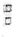
27” Units - under gas cooktop
27
1
/16"
(687mm)
29
1
/16"
(738mm)
24
7
/16"
(621mm)
36"
(914mm)
Note: Dimensions based on standard countertop height (36" with 4
3
/4" toe kick
including base plate).
T
he built-in oven can be installed below the induction cooktop as long as there
is an air clearance of 1" between the bottom of the cooktop and the top of the oven.
SUMP
4
3
/16"
(106mm)
3
1
/8"
(79mm)
1
1
/16"
(27mm)
4"
(102mm)
6
3
/4"
(172mm)
2
3
/4"
(70mm)
4
3
/4"
(121mm)
Fitting/
Conduit
Heat shield: Self positioning – 2
3
/8" length,
Minimum required air clearance: 1" (26mm)
TOE KICKTOE KICK
COOKTOP
OVEN
COUNTERTOP
3"(76mm)
28
1
/4"
(718mm)
27” Units - under induction cooktop

English 6
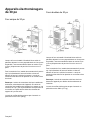
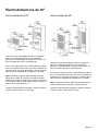
Dimensions for 30”
Wall-Mounted Units
Single Oven 30”
It is good practice, when oven is installed at the end of a
cabinet run, adjacent to a perpendicular wall or cabinet
door, to allow at least 1/4” space between the side of the
oven and the wall/door.
For oven support, install 2x4’s extending front to back flush
with the bottom and the side of the opening. The supporting
base must be well secured to the floor/cabinet and level.
Note:
The conduit box must be installed either above or below
the unit. If the conduit box is installed below the unit, a 2”
diameter hole or space is required between the back wall
and the right rear of the 2x4 supports.
The cabinet base must be flat and capable of supporting a
weight of at least 212 lbs (96 kg).
Double Oven 30”
It is good practice, when oven is installed at the end of a
cabinet run, adjacent to a perpendicular wall or cabinet
door, to allow at least 1/4” space between the side of the
oven and the wall/door.
For oven support, install 2x4’s extending front to back flush
with the bottom and the side of the opening. The supporting
base must be well secured to the floor/cabinet and level.
Note:
The conduit box must be located above the unit to facilitate
connecting and servicing.
The cabinet base must be flat and capable of supporting a
weight of at least 390 lbs (177 kg).
27 1/16”
(687mm)

English 7
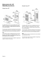
Combo Oven with Microwave 30”
It is good practice, when oven is installed at the end of a
cabinet run, adjacent to a perpendicular wall or cabinet
door, to allow at least 1/4” space between the side of the
oven and the wall/door.
For oven support, install 2x4’s extending front to back flush
with the bottom and the side of the opening. The supporting
base must be well secured to the floor/cabinet and level.
Note:
The conduit box must be located above the unit to facilitate
connecting and servicing.
The cabinet base must be flat and capable of supporting a
weight of at least 310 lbs (141 kg).
Combo Oven with Microwave and
Warming Drawer 30”
It is good practice, when oven is installed at the end of a
cabinet run, adjacent to a perpendicular wall or cabinet
door, to allow at least 1/4” space between the side of the
oven and the wall/door.
For oven support, install 2x4’s extending front to back flush
with the bottom and the side of the opening. The supporting
base must be well secured to the floor/cabinet and level.
Note:
The conduit box must be located above the unit to facilitate
connecting and servicing.
The cabinet base must be flat and capable of supporting a
weight of at least 429 lbs (195 kg).

English 8
Dimensions for 30” Under-the-counter-
Units
It is good practice, when oven is installed at the end of a
cabinet run, adjacent to a perpendicular wall or cabinet
door, to allow at least 1/4” space between the side of the
oven and the wall/door.
For oven support, install 2x4’s extending front to back flush
with the bottom and the side of the opening. The supporting
base must be well secured to the floor/cabinet and level.
This Built –In Oven can be installed below any Thermador
cook top as long as there is no contact between the bottom
of the cook top and the top of the oven, except for the
Thermador Induction cooktop, where the gap must be of at
least 1 inch.
36
"
(915m
m)
20
"
(508mm)
28
1/4"
(718mm)
16
1/2"
(419mm)
24
"
(610mm)
4
3/4"
(121mm)
28
1/2"
(724mm)
23
7/8"
(606mm)
22
"
(559mm)
29
1/16"
(738mm)
29
3/4"
(755mm)
27
13/16"
(706mm)
27 1/16”
(687mm)
min. 3
"
(76mm)
27
1
/
16
"
(687mm)
29
1
/
16
"
(738mm)
24
7
/
16
"
(621mm)
36"
(914mm)
SUMP
4
3
/
16
"
(106mm)
3
15
/
16
"
(99mm)
4
15
/
16
"
(125mm)
6
3
/
4
"
(172mm)
1
13
/
16
"
(47mm)
1
/
4
"
(7mm)
4
3
/
4
"
(121mm)
Note: Dimensions based on standard countertop height (36" with 4
3
/
4
" toe kick
including base plate).
The built-in oven can be installed below the electric cooktop as long as there is
no contact between the bottom of the cooktop and the top of the oven.
TOE KICK
COOKTOP
OVEN
TOE KICK
COUNTERTOP
3"
(76mm)
28
1
/
4
"
(718mm)
Fitting/
Conduit
30” Units - under electric cooktop
27
1
/
16
"
(687mm)
29
1
/
16
"
(738mm)
24
7
/
16
"
(621mm)
36"
(914mm)
SUMP
COOKTOP
OVEN
COUNTERTOP
Gas
Connection
4
3
/
16
"
(106mm)
3
13
/
16
"
(97mm)
3"
(76mm)
5
11
/
16
"
(144mm)
6
3
/
4
"
(172mm)
1
1
/
8
"
(28mm)
3
/
8
"
(9mm)
4
3
/
4
"
(121mm)
Note: Dimensions based on standard countertop height (36" with 4
3
/4" toe kick
including base plate).
The built-in oven can be installed below the gas cooktop as long as there is no
contact between the bottom of the cooktop and the top of the oven.
28
1
/
4
"
(718mm)
TOE KICK
30” Units - under gas cooktop

English 9
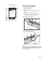
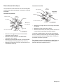
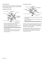
Removing Packaging
• Cut straps on outside of box.
• Remove cardboard box.
• Remove all top and side cardboard and Styrofoam
braces.
• Place oven in front of cabinets where it is to be
installed.
• Unscrew unit from Left and Right Brackets as show in
“Left and Right Packaging Bracket Removal.”
Left Packaging Bracket Removal
Right Packaging Bracket Removal
Note:
Different models use different packaging materials. Actual
brackets may look differently. Bracket remains in packaging
base. Unit should stay on packaging base until ready to be
lifted into cabinet cutout.
27
1
/16"
(687mm)
29
1
/16"
(738mm)
24
7
/16"
(621mm)
36"
(914mm)
Note: Dimensions based on standard countertop height (36" with 4
3
/4" toe kick
including base plate).
T
he built-in oven can be installed below the induction cooktop as long as there
is an air clearance of 1" between the bottom of the cooktop and the top of the oven.
SUMP
4
3
/16"
(106mm)
3
1
/8"
(79mm)
1
1
/16"
(27mm)
4"
(102mm)
6
3
/4"
(172mm)
2
3
/4"
(70mm)
4
3
/4"
(121mm)
Fitting/
Conduit
Heat shield: Self positioning – 2
3
/8" length,
Minimum required air clearance: 1" (26mm)
TOE KICKTOE KICK
COOKTOP
OVEN
COUNTERTOP
3"(76mm)
28
1
/4"
(718mm)
30” Units - under induction cooktop

English 10
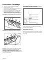
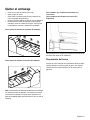
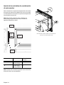
For Convection Microwave Combination Units
(for Convection Microwave Combination Units Only)
Remove Convection Microwave Shipping Bracket Screw
prior to installation.
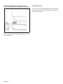
Preparing Oven
Place oven in front of cabinets where it is to be installed.
Rest it on a jack or other sturdy support so that it is in line
with the cabinet cutout.

English 11
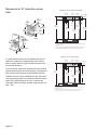
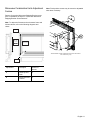
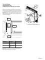
Microwave Combination Units Adjustment
Feature
Remove Convection Microwave Shipping Bracket screw
prior to installation as shown in “Convection Microwave
Shipping Bracket Screw Removal.”
Note: To adjust the fit between the microwave frame and
kitchen cabinet, refer to the following diagrams and
charts.
Note: Fixed position screws may be moved to adjustable
slots when necessary.
Adjustment Description Number of
Screws
A Frame Up and
Down
4
B Frame Back and
Forward
8
A: Frame
Up and Down
Microwave
B: Frame
Back and
Forward
Frame
A
B
B
This illustration shows models with convection microwave.
Your model may vary.

English 12
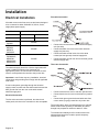
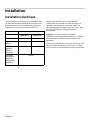
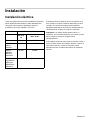
Installation
Electrical Installation
All model ovens on the front cover are dual rated, designed
to be connected to either 208/240V AC, 60 Hz, 4 wire,
single-phase power supply.
The electrical supply should be a 4-wire single-phase AC.
Install a suitable conduit box (not furnished). An
appropriately-sized, UL-listed conduit connector must be
used to correctly attach the conduit to the junction box.
Important: Local Codes may vary; installation, electrical
connections and grounding must comply with all applicable
local codes.
If local codes permit grounding through the electrical
supply neutral, connect both the white neutral wire and the
bare ground wire from the oven to the white neutral
electrical supply wire.
Electrical Connection
The four-wire connection is preferred, but where local
codes permit, the three wire connection is also acceptable.
Four-wire Connection
• Connect the red oven wire to the red electrical supply
wire (hot wire).
• Connect the black oven wire to the black electrical
supply wire (hot wire).
• Connect the white neutral oven wire to the white
neutral (not bare ground) electrical supply wire.
• Connect the bare ground oven wire to the bare ground
electrical supply wire.
Three-wire Connection
• Connect red wire from oven to red wire injunction box.
• Connect black wire from oven to black wire in junction
box.
• Connect both green ground wire and white wire from
oven to white (or gray) neutral wire in junction box.
The conduit cable, where connected at the oven, swivels.
Rotate conduit cable upward (or downward) and direct
through hole prepared in cabinet to attach to J-Box.
To maintain serviceability, the flex conduit must not be
shortened and should be routed to permit temporary
removal of the oven.
Model Circuit Required
208V, 60 Hz 240V, 60 Hz
M301 25 AMP 30 AMP
ME301, ME271,
POD301
30 AMP
ME302,
MED302,
MED272,
PODC302
40 AMP
PODM301,
PODMW301,
MEMC301,
MEMCW301,
MEMCW271
50 AMP

English 13
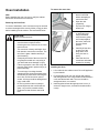
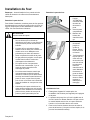
Oven Installation
Note:
Before installing the oven, be sure to verify the cabinet
dimensions and electrical connections.
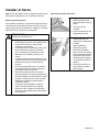
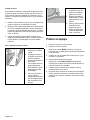
Removing the Oven Door
For ease of installation, some oven doors may be removed
to reduce the weight of the oven by 30 lbs (14 kg) per door,
before installing into the cabinet. See instructions below.
To remove the oven door:
Installing the Oven
1. Lift or slide unit into cabinet cutout. Do not lift appliance
by door handle.
2. Push straight in until oven trim is flush with cabinet
wall, being careful not to crimp flexible conduit between
oven and cabinet back wall. The oven should be
straight and level, not crooked.
3. Install supplied screws through tap holes in trim. (2
screws for single ovens, 4 screws for double/combo
ovens)
CAUTION:
When removing the door:
• Make sure oven is cool and power to the
oven has been turned off before
removing the door. Failure to do so could
result in burns.
• The oven door is heavy and fragile. Use
both hands to remove the oven door. The
door front is glass. Handle carefully to
avoid breaking.
• Grasp only the sides of the oven door. Do
not grasp the handle as it may swing in
your hand and cause damage or injury.
• Failure to grasp the oven door firmly and
properly could result in personal injury or
product damage.
• To avoid injury from hinge bracket
snapping closed, be sure that both levers
are securely in place before removing the
door. Also, do not force door open or
closed - the hinge could be damaged and
injury could result.
• Do not lay removed door on sharp or
pointed objects as this could break the
glass. Lay on a flat, smooth surface,
positioned so that the door cannot fall
over.
1. Be sure to read the
above CAUTION
before attempting to
remove the door.
2. Open the door
completely.
3. Flip levers on hinges
toward you.
4. Holding the door firmly
on both sides and
using both hands,
close the door gently
until it stops against
the levers, about 30º
from the closed
position.
5. Carefully lift the door
up and out of the
hinge slots. Hold
firmly; the door is
heavy.
6. Place the door in a
convenient and stable
location for cleaning.

English 14
To replace the oven door:
Testing Operation
1. Turn on power at the breaker.
2. Test the oven mode.
Select the BAKE mode. See the Use and Care Manual
for detailed operation instructions.
3. Verify that the oven light comes on and the oven
begins to preheat.
4. Test the door lock.
Set the SELF CLEAN mode. Confirm that the door
locks when the lock icon appears in the display.
5. If installing a double oven, test the second oven as
well.
6. If any of the tests do not result as explained above,
contact Thermador service for assistance. Otherwise,
the installation is complete at this time.
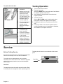
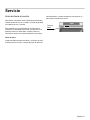
Service
Before Calling Service
See Use and Care Manual for troubleshooting information.
Refer to the Warranty in the Use and Care Manual.
To reach a service representative, see the contact
information at the front of the manual. Please be prepared
with the information printed on your product data plate
when calling.
Data Plate
The data plate shows the model and serial number. Refer
to the data plate on the appliance when requesting service.
The data plate is located on the underside of the control
panel:
1. Hold the door firmly in
both hands.
2. Hold the door at a 30º
angle from the closed
position and insert
hinges into the slots.
You may need to rock
the door forward and
backward slightly to
seat the hinge feet.
3. The door may need to
be removed and re-
inserted until the
hinges sit correctly in
the slots.
4. Open door all the way
to expose hinges,
levers, and slots.
5. Push levers foreward
and down until seated
on the bracket.
6. Close and open door
slowly to be sure it is
correctly and securely
in place. Door must be
straight, not crooked.
Data Plate
Page is loading ...
Page is loading ...
Page is loading ...
Page is loading ...
Page is loading ...
Page is loading ...
Page is loading ...
Page is loading ...
Page is loading ...
Page is loading ...
Page is loading ...
Page is loading ...
Page is loading ...
Page is loading ...
Page is loading ...
Page is loading ...
Page is loading ...
Page is loading ...
Page is loading ...
Page is loading ...
Page is loading ...
Page is loading ...
Page is loading ...
Page is loading ...
Page is loading ...
Page is loading ...
Page is loading ...
Page is loading ...
Page is loading ...
Page is loading ...
Page is loading ...
Page is loading ...
Page is loading ...
Page is loading ...
Page is loading ...

5551 McFadden Avenue, Huntington Beach, CA 92649 • 800-735-4328 • www.thermador.com
9000432742 • 5V0G8B • Rev A • 09/09 © BSH Home Appliances Corporation, 2007 • All rights reserved
Litho in USA
-
 1
1
-
 2
2
-
 3
3
-
 4
4
-
 5
5
-
 6
6
-
 7
7
-
 8
8
-
 9
9
-
 10
10
-
 11
11
-
 12
12
-
 13
13
-
 14
14
-
 15
15
-
 16
16
-
 17
17
-
 18
18
-
 19
19
-
 20
20
-
 21
21
-
 22
22
-
 23
23
-
 24
24
-
 25
25
-
 26
26
-
 27
27
-
 28
28
-
 29
29
-
 30
30
-
 31
31
-
 32
32
-
 33
33
-
 34
34
-
 35
35
-
 36
36
-
 37
37
-
 38
38
-
 39
39
-
 40
40
-
 41
41
-
 42
42
-
 43
43
-
 44
44
-
 45
45
-
 46
46
-
 47
47
-
 48
48
-
 49
49
-
 50
50
-
 51
51
-
 52
52


Thermador PODC302J Installation guide
- Category
- Microwaves
- Type
- Installation guide
- This manual is also suitable for
Ask a question and I''ll find the answer in the document
Finding information in a document is now easier with AI
in other languages
- français: Thermador PODC302J Guide d'installation
- español: Thermador PODC302J Guía de instalación
Related papers
-
Thermador MED302 User manual
-
Thermador MEMCW301EP-03 Installation guide
-
Thermador MB30WS Installation guide
-
Thermador MB30WP Installation guide
-
-
-
Thermador MC30WP Installation guide
-
-
-
Thermador MC30WS Installation guide
Other documents
-
Bosch HBL33 Owner's manual
-
Bosch HBL33 Installation guide
-
Kenmore C970-40419903 User manual
-
Bosch HBL5351UC Installation guide
-
-
-
-
-
-
Bosch HBL8451UC Installation guide