English 7
7. Continue with the unit installation in the following
sections on electrical connection and installing the
oven unit into the wall cabinet.
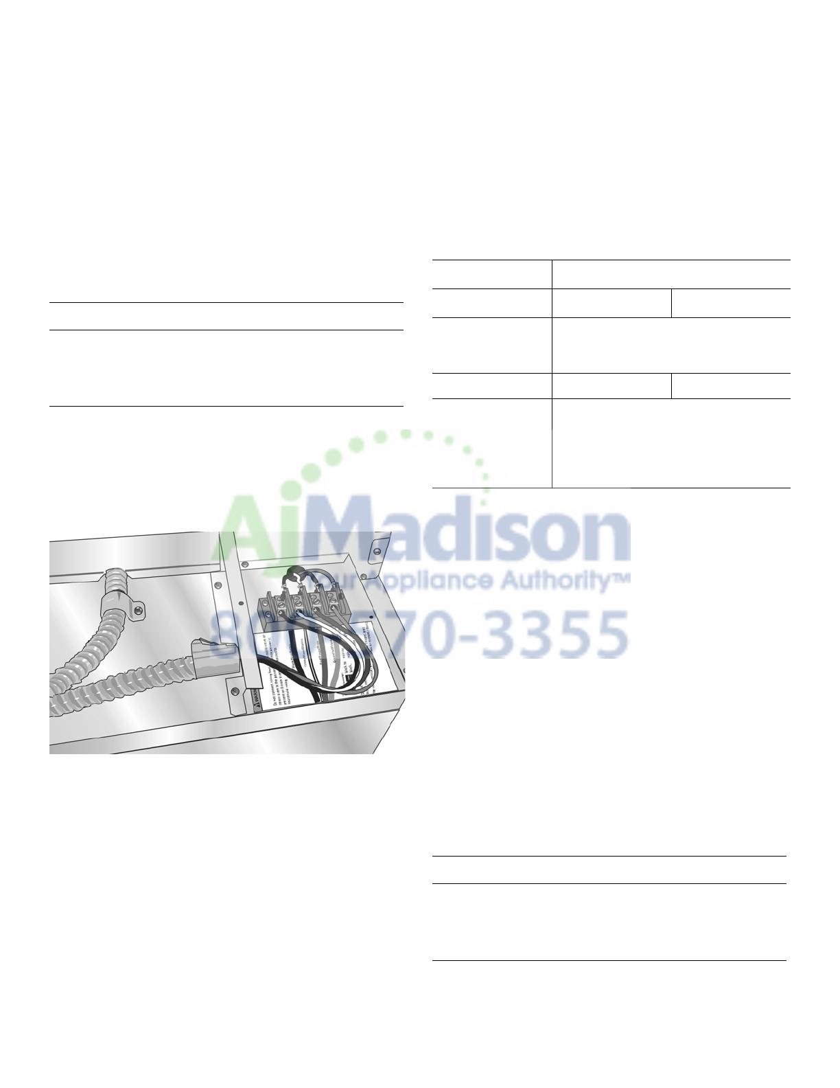
Connecting the Microwave Oven or Steam
Oven Electrical Conduit to the Single Oven
Note: If installing the oven with a microwave or steam oven
mounted as a combination unit, the microwave oven or
steam oven power cable must be properly attached to the
oven-mounted junction box. This must be done prior to
supplying electric power to the oven unit.
1. Check to be sure there is no electric power supplied to
the oven.
2. Remove the oven mounted junction box cover (located
on the rear top of the oven).
3. Remove the cap from the conduit access hole in the
side of the oven mounted junction box.
4. Guide the four wires from the conduit cable coming
from the microwave or steam oven through the hole in
the oven mounted junction box.
5. Snap the conduit connector into the hole by pressing it
in until it clicks into place.
6. Follow the wiring diagram label and match and connect
each wire by color to the wires attached to the wiring
block inside the oven mounted junction box. Push the
bare end of the wire until it is snug in the wiring block
then tighten down the retaining screw on each wire.
Tighten securely, but do not over tighten.
7. Replace the oven mounted junction box cover and
tighten the two screws holding it in place. Tighten the
screws securely, but do not over tighten.
8. Refer to the Electrical Connection section for further
information to complete the electrical connection of the
combination unit to the main power supply.
Electrical Installation
All model ovens on the front cover of this installation
instruction manual are dual rated, designed to be
connected to either 208 or 240V AC, 60 Hz, 4 wire, single-
phase power supply.
The electrical supply should be a 4-wire single-phase AC.
Install a suitable conduit box (not furnished). An
appropriately-sized, UL-listed conduit connector must be
used to correctly attach the conduit to the junction box.
Important: Local Codes may vary; installation, electrical
connections and grounding must comply with all applicable
local codes.
If local codes permit grounding through the electrical
supply neutral, connect both the white neutral wire and the
green ground wire from the oven to the white neutral
electrical supply wire.
Important: If you have purchased a combination oven unit
(one that includes a microwave or steam oven over the
single oven), see the preceding section “Connecting the
Microwave Oven or Steam Oven Electrical Conduit to the
Single Oven” showing electrical connection of the
combination unit components.
9 WARNING
Disconnect the oven from the electric power supply
before connecting the microwave oven or steam
oven wiring. Failure to do so could result in electrical
shock and injury or death.
Model Circuit Required
208V, 60 Hz 240V, 60 Hz
HBN54, HBN84,
HBL53, HBL54,
HBL84, HBLP4
30 AMP
HBL55
30 AMP 40 AMP
HBN56, HBL56,
HBL57, HBN86,
HBL86, HBL87,
HBLP6, HBLP7,
HSLP7
40 AMP
9 WARNING
Complete the connection of the microwave or steam
oven conduit to the single oven before proceeding
with the unit electrical connection to the main power
supply.


