Page is loading ...

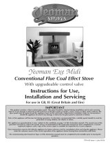
STUDIO
Balanced Flue
Instructions for Use,
Installation and Servicing
For use in GB, IE (Great Britain and Eire)
PR0919 Issue 5 (January 2008)
IMPORTANT
Do not attempt to burn rubbish in this appliance. This appliance must only be operated with the glass door secured firmly in
position. The front casing of this appliance will become hot whilst in operation, it is therefore recommended that a suitable
guard should be used for the protection of young children, the elderly or infirm.
These instructions must be left at the property for future reference and when servicing the fire.
The Commissioning Sheet found on page 3 must be completed by the Corgi Installer.
This appliance has been certified for use in countries other than those stated. To install this appliance in these countries, it is essential to obtain the
translated instructions and in some cases the appliance will require modification. Contact Gazco for further information.

2
COVERING THE FOLLOWING MODEL:
STUDIO 1 BALANCED FLUE: STUDIO 2 BALANCED FLUE:
8700BFCHEC 8701BFCHEC
P8700BFCHEC P8701BFCHEC
PAGE
APPLIANCE COMMISSIONING CHECKLIST 3
USER INSTRUCTIONS 4
INSTALLATION INSTRUCTIONS 8
Technical Specifications 8
Site Requirements
Installation 14
SERVICING INSTRUCTIONS 22
Fault Finding 22
How to replace parts 24
Basic spare parts list 30
Service Records 31

3
FLUE CHECK PASS FAIL
1. Flue is correct for appliance
2. Flue flow test N/A
3. Spillage test N/A
GAS CHECK
1. Gas soundness & let by test
2. Standing pressure test mb
3. Appliance working pressure (on High Setting) mb
NB All other gas appliances must be operating on full
4. Gas rate m
3
/h
5. Does ventilation meet appliance requirements N/A
APPLIANCE COMMISSIONING CHECKLIST
Dealer .....................................................................
...............................................................................
...............................................................................
Contact No. ..............................................................
Date of Purchase .......................................................
Model No. ................................................................
Serial No. .................................................................
Gas Type ..................................................................
Installation Company ................................................
. . . . . . . . . . . . . . . . . . . . . . . . . . . . . . . . . . . . . . . . . . . . . . . . . . . . . . . . . . . . . . . . . . . . . . . . . . . . . . . .
. . . . . . . . . . . . . . . . . . . . . . . . . . . . . . . . . . . . . . . . . . . . . . . . . . . . . . . . . . . . . . . . . . . . . . . . . . . . . . . .
Engineer ...................................................................
Contact No. ...............................................................
Corgi Reg No. ............................................................
Date of Installation ....................................................
IMPORTANT NOTICE
Explain the operation of the appliance to the end user, hand the completed instructions to them for safe keeping,
as the information will be required when making any guaranteed claims.
DEALER AND INSTALLER INFORMATION
This product is guaranteed for 2 years from the date of installation, as set out in the terms and conditions of sale between Gazco and your
local Gazco dealer. This guarantee will be invalid, to the extent permitted by law, if the above Appliance Commissioning Checklist is not
fully completed by the installer and available for inspection by a Gazco engineer. The guarantee will only be valid during the second year,
to the extent permitted by law, if the annual service recommended in the Instructions for Use has been completed by a Corgi registered
engineer, and a copy of the service visit report is available for inspection by a Gazco engineer.

4
USER INSTRUCTIONS
1. GENERAL
1.1 A competent person must carry out installation and
servicing.
1.2 In all correspondence, please quote the appliance type and
serial number, which can be found on the data badge
located on a plate under the access panel, see Diagram 2,
Installation.
1.3 Do not place curtains above the fire:
You must have 300mm (1’) clearance between the fire and
any curtains at either side.
1.4 If any cracks appear in the glass panel do not use the
appliance until the panel has been replaced.
1.5 In the unlikely event the appliance is receiving interference
from other electronic devices, the handset/Control box can
be reprogrammed. Please consult your dealer if you think
this may be the case.
1.6 If, for any reason, the flue has to be removed from the
appliance, the seals must be replaced in the inner spigot.
1.7 Do not obstruct the flue terminal in any way, i.e. by
planting flowers, trees shrubs etc in the near vicinity, or by
leaning objects up against the terminal guard.
1.8 Do not use a garden sprinkler or hose near the terminal.
1.9 This product is guaranteed for 2 years from the date of
installation, as set out in the terms and conditions of sale
between Gazco and your local Gazco dealer. Please consult
with your local Gazco dealer if you have any questions. In
all correspondence always quote the Model Number and
Serial Number.
2. LIGHTING THE STUDIO
There are two ways of lighting the Studio:
• bythermostaticremotecontrol,see2A
•usingthefire’stouchpad,see2B
2A - THERMOSTATIC and TIMER REMOTE CONTROL
1
AR1883
Turning the Studio On
Your remote can control the gas fire from pilot ignition
through to shut down.
To turn the fire on:
• PresstheOFFbuttonandtheUParrowsimultaneously
The pilot and main burner ignite and the remote is now in
ManualMode.In‘MANUALMODE’youcan:
• turnonthemainburner
• regulatetheflamefromlowtohighandback
• turnofftheburnerleavingjustthepilotburning
In‘TEMPMODE’youcan:
• settheroomtemperaturesothethermostatinthe
remote automatically maintains that temperature
In‘TIMERMODE’thestove:
• turnsonandoffaccordingtothesettimeperiods
• automaticallyregulatestheroomtemperatureduringthe
set periods
NOTE: Wh E N O p E r a T i N g T h E f i r E iN TE m p O r Ti m E r m O d E ,
T h E p i l O T r E m a i N s l i T a N d T h E f i r E T h E N a u T O m a T i c a l l y
s W i T c h E s O N a T p r O g r a m m E d T i m E s T O b r i N g T h E r O O m T O
T h E s E T T E m p E r a T u r E W h E T h E r O r N O T y O u a r E iN T h E r O O m .
NEVER LEAVE ANY COMBUSTIBLE MATERIALS WITHIN 1
METRE OF THE FRONT OF THE APPLIANCE.
2.1 SWITCHING BETWEEN MODES
• PresstheSETbuttontochangetoManualOperation
• PressagaintochangetoTemperatureMode
• Keeppressingtorunthroughalloperatingmodes.These
are:
• MAN
• DAY TEMP
• NIGHTTEMP
• TIMER
and back to MAN
NOTE: MAN mode can also be reached by pressing
either the UP or DOWN arrow
2.2 MAN MODE
•PressboththeUParrowandimmediatelypresstheOFF
button to light the appliance. You hear a click as the fire
begins the ignition process , (up to 30 seconds)
• PresstheOFFbuttontoturntheapplianceoff
INCREASINGTEMPERATURE
• PresstheUParrowoncetoincreaseflameheightone
stage
• PressandholdtheUParrowtoincreasetomaximum

5
USER INSTRUCTIONS
DECREASINGTEMPERATURE
• PresstheDOWNarrowoncetodecreaseflameheight
one stage
• PressandholdtheDOWNarrowtodecreaseto
minimum
At the lowest point the fire goes to ‘standby mode’ (only
pilot lit)
NOTE: While pressing a button a symbol indicating
transmission appears on the display. The receiver
confirms transmission with an acoustic signal.
Turning the Studio Off
• PresstheOffbuttontoextinguishthepilot
2.3 TEMP MODE
The display shows the current room temperature.
To increase or decrease the fire’s output:
• PresstheSETbuttontoselecteithertheDAYTEMP
ortheNIGHTTEMPmodebybrieflypressingthe
SETbutton
• HoldtheSETbuttonuntiltheTEMPdisplayflashesand
then let go
• SetthedesiredtemperaturewiththeUPandDOWN
arrows. (Minimum temperature 5C, maximum 30C or
fahrenheit)
• PresstheOFFbuttontostopthedisplayflashingorwait
toreturntoTEMPmode.
NOTE: If you set a temperature that is beneath the
current room temperature, the fire automatically
switches to OFF.
NOTE: If you would like the Night temperature control to
turn off then decrease the temperature until [---] is
displayed.
2.4 TIMER MODE
There are two programmable settings you can make over a
24 hour period, P1 and P2
P1 + = Start Timed Setting 1
P1 + =EndofTimedSetting1
P2 + = Start Timed Setting 2
P2 + =EndofTimedSetting2
2.4.1 P1 - Program 1 for a Timed Setting
• PresstheSETbuttonuntiltheTIMERmodeisdisplayed
• HoldtheSETbutton.Thedisplaysflashesthecurrent
time for P1. While the time displayed is flashing you can
alter the hours and minutes set.
To set the time your fire first lights, change the Start Timed
Setting for P1 .
•PresstheUParrowtoalterthehour
•PresstheDOWNarrowtoaltertheminutes
in 10 minute increments
•PressSETagaintomovetotheEndofTimedSetting,
P1. The display shows the current setting for P1
This is the time your Studio first shuts down:
•PresstheUParrowtoalterthehour
•PresstheDOWNarrowtoaltertheminutes
2.4.2 P2 - Program 2 for a Timed Setting
Use the same steps outlined in 2.4.1 to change the setting
for P2.
If you have already set P1 and want to alter the setting for
P2 only:
• PresstheSETbuttonuntilTIMERmodeisdisplayed
•HoldtheSETbuttonuntil the display flashes the
current time for P1
•PresstheSETbuttonagaintoscrollpastthesettingsfor
P1 and P1
Withthetimestillflashing:
•PresstheUParrowtoalterthehour
•PresstheDOWNarrowtoaltertheminutes
OnceallfourtimesaresetpresstheOFFbuttonorsimply
wait to complete programming.
2.5 LOW BATTERY
“BATT” is displayed on the remote when its batteries need
replacement.
2.6 SETTING THE TIME
• Simultaneouslypresstheupanddownarrowbuttons
• Presstheuparrowtosetthehourandthedownarrow
to set the minutes
• PressOFFtoreturntothemanualmodeorsimplywait
2.7 SETTING THE °C/24 HOUR OR °F/12 HOUR CLOCK
• PressOFFandthedownarrowuntilthedisplaychanges
from °C/24 hour clock to °F/12 hour clock and vice
versa.
If the remote is removed, lost or damaged, signals
transmitted to the receiver cease. Your fire will go to
standby (pilot) mode after 6 hours.
TOUCH PAD CONTROL
6
AR1887
• PresstheON-OFFbuttontolighttheappliance,(upto
30 seconds)
• PresstheUPbuttontoincreasetheflameheight
• PresstheDOWNbuttontodecreasetheflameheight.At
the lowest point it goes to ‘standby mode’, (only pilot
lit)

6
USER INSTRUCTIONS
• PresstheON-OFFbuttontoturntheapplianceoff
EMERGENCY SHUT OFF
If the batteries fail during use of the fire, move the switch to
theOFF(O)position,Diagram3
(ThisswitchissettobeONduringnormaloperationand
mustremainON)
3
AR1933
3. CLEANING THE STUDIO
3.1 Make sure the fire and surrounds are cool before cleaning..
Use:
• Adryclothorstainlesssteelproducttocleanthe
polished plate
• Adampclothforthepaintedfirebox
• Adampclothtocleanthegranite/enamelledinnerpanels
• Usesoapandwatertocleantheglass
3.2 Opening the Glass Window
3.2.1 Steel Frame
[If fitted with a Steel Frame, this needs to be removed
first:
• Lifttheframeupwardsoffitsfoursupportbrackets,
Diagram 4
4
AR1981
3.3 All models
Using the allen key provided:
• Releasethetwowindowlocksatthetopoftheglass
door, Diagram 5. The locks to move from shut to open
towards the outer edges of the glass door, Diagram 5
5
AR1860
• Supporttheframeandletitfallgentlyforward
• Openitdowntoitsstopposition
When closing the window ensure the window catches are
fully engaged.
4. CHANGING THE STUDIO BATTERIES
The appliance batteries are located under the polished plate
mounting the wall switch.
• Undothetwoscrewssecuringthewallswitchandplate
and remove, Diagram 6
6
AR1887
• CorrectlypositionthefournewAAsizebatteries
• Re-assemblethebatteryholderasshowninDiagram7
• Ensurethetouchpadcableistuckedtotheleftonfitting
the wall plate back onto the wall
7
AR1932

7
USER INSTRUCTIONS
5. ARRANGEMENT OF FUEL BED
5.1 If you need to replace pebbles or refill the tray, make sure
the pebbles are flattened so they are level with the rim of
the tray.
TAKE CARE NOT TO SPILL PEBBLES INTO THE PILOT
AREA
ONLY PEBBLES SUPPLIED BY GAZCO CAN BE USED IN
THIS FIRE
6. FLAME FAILURE DEVICE
6.1 This is a safety feature incorporated on this appliance which
automatically switches off the gas supply if the pilot goes
out and fails to heat the thermocouple.
7. RUNNING IN
7.1 ThesurfacecoatingonthemetalusedinyourGAZCOfire
will "burn off" during the first few hours of use producing a
harmless and temporary odour. This will disappear after a
short period of use. If the odour persists, ask your installer
for advice.
8. SERVICING
8.1 The fire must be serviced every 12 months by a qualified
GasEngineer.Inallcorrespondencealwaysquotethe
Model number and the Serial number which may be found
on the data badge.
9. VENTILATION
12.1 Any purpose provided ventilation should be checked
periodically to ensure that it is free from obstruction.
10. INSTALLATION DETAILS
13.1 Your installer should have completed the commissioning
sheet at the front of this book. This records the essential
installation details of the appliance. In all correspondence
always quote the Model number and Serial number.
11. HOT SURFACES
14.1 Parts of this appliance become hot during normal use.
• Regardallpartsoftheapplianceasa‘workingsurface’
• Provideasuitablefireguardtoprotectyoungchildren
and the infirm
12. FIRE WILL NOT LIGHT
15.1 If you cannot light the Studio:
• CheckthattheemergencyshutoffswitchisintheON
(1) position, see Section 2, Emergency Shut Off
•Checkandchangethebatteriesintheremotehandset
• Checkandchangetheappliancebatteries,Section4.
Consult your Gazco dealer if the Studio still does not light.

8
Model Gas
CAT.
Gas
Type
Working
Pressure
Aeration Injector Gas Rate
m
3
/h
Input kW (Gross) Country
High Low
Studio 1 BF 12H Natural
G20
20mbar 16 x 23 400 0.600 6.3 3.0 GB, IE
Studio 1 BF 13P
Propane
G31 37mbar
14 x 16 (1)
16 x 23 (1) 185 0.230 6.1 3.0 GB, IE
Studio 2 BF 12H Natural
G20
20nbar 14 X 16 600 0.800 8.4 4.3 GB, IE
Studio 2 BF 13P
Propane
G31 37 mbar
14 x 16 (1)
16 x 23 (1) 225 0.275 7.3 4.0 GB, IE
Efciency Class 2 - 81% / NO
x
Class 4
Flue Outlet Size Ø 150mm
Flue Inlet Size Ø 100mm
Gas Inlet Connection Size Ø 8mm
RESTRICTOR REQUIREMENT
VERTICAL & HORIZONTAL FLUE
STUDIO 1 BF STUDIO 2 BF
Vertical Flue Height Horizontal Length Restrictor
Size
Vertical Flue Height Horizontal Length Restrictor Size
200mm - 500mm Up to 500mm No restrictor 700mm - 1490mm Up to 1000mm No restrictor
500mm - 100mm Up to 1000mm No restrictor 1500mm - 2490mm Up to 5000mm No restrictor
1000mm - 1490mm Up to 1000mm
70mm Ø
2500mm - 3000mm Up to 5000mm
75mm Ø
1500mm - 1990mm Up to 5000mm
70mm Ø
2000mm - 3000mm Up to 5000mm
60mm Ø
TOP EXIT - VERTICAL ONLY INCLUDING OFFSET
STUDIO 1 BF STUDIO 2 BF
Vertical Flue Height Restrictor Size Vertical Flue Height Restrictor Size
3000 - 4990mm
Ø 52mm
3000mm - 4990mm
Ø 60mm
5000mm - 10,000mm
Ø 47mm
5000mm - 10,000mm
Ø 52mm
INSTALLATION INSTRUCTIONS
TECHNICAL SPECIFICATION
COVERING THE FOLLOWING MODELS:
STUDIO 1 BF: STUDIO 2 BF:
8700BFCHEC 8701BFCHEC
P8700BFCHEC P8701BFCHEC

9
INSTALLATION INSTRUCTIONS
TECHNICAL SPECIFICATION
This appliance has been certified for use in countries other than
those stated. To install this appliance in these countries, it is
essential to obtain the translated instructions and in some cases
the appliance will require modification. Contact Gazco for further
information.
PACKING CHECKLIST
Qty Description Fixing Kit containing:-
1WhiteStoneChippings 1 x Instruction Manual
4xWoodScrews
4 x Rawl Plugs
1 x Handset
4 x AA cell batteries
1 x 9V cell batteries
1 x wall box
1 x touch pad/wall plate
1 x battery holder
745 - Studio 1BF
945 - Studio 2BF
820 - Studio 1BF
1020 - Studio 2BF

10
INSTALLATION INSTRUCTIONS
TECHNICAL SPECIFICATION
Steel Frame
Dimensions
Dimension Studio 1
Studio 2
A 1120 1350
B 675 675
C 646 846
D 320 320
E 177 177
F 237 237
G 25 25
Profil Frame
Dimensions
Dimension Studio 1
Studio 2
A 836 1036
B 510 510
C 740 940
D 414 414
E 48 48
F 48 48
G 12.5 12.5
Bauhaus Frame
Dimensions
Dimension Studio 1
Studio 2
A 850 1050
B 524 524
C 740 940
D 414 414
E 55 55
F 55 55
G 28 28
2
Steel
Profil
Bauhaus

11
INSTALLATION INSTRUCTIONS
SITE REQUIREMENTS
Note: This appliance must only be installed with the flue
supplied.
You must adhere to the following:
1.1 The flue must be sited in accordance with BS5440: Part 1
(latest edition). See Diagram 1.
1.2 Fit a guard to protect people from any terminal less than 2
metres above any access such as level ground, a balcony or
above a flat roof.
1.3 All vertical and horizontal flues must be securely fixed and
fire precautions followed in accordance with local and
national codes of practice.
1.4 A restrictor may be required. Refer to Technical
Specifications on page 12.
1.5 Two types of flue terminals are available, horizontal and
vertical. To measure for a horizontal terminal:
• Decideontheterminalposition
• Measuretheheightfromthetopoftheappliancetothe
centre of the required outlet.
For minimum and maximum flue dimensions see Diagram
1A / 1B.
• Allowenoughroomeitheraboveortothesideofthe
appliance to assemble the flue on top
• Assembleahorizontalflueinthefollowingorder:
-Verticalsection
-90°elbow
-Horizontalplusterminal
• Supporttheopeningofamasonryinstallationwitha
lintel.
1.7 Onlythehorizontalterminalsectioncanbereducedinsize.
1. FLUE AND CHIMNEY REQUIREMENTS
1
UK Dimensions

12
STUDIO 1 BF
1A
AR1671
STUDIO 2 BF
1A
AR1971
Start of bend to centre line of horizontal flue 170mm.
Centre line of vertical flue to end of bend 220mm.
2.1 TOP FLUE UP & OUT KIT
STUDIO 1 BF (8534/8534AN)
Vertical from the top of the appliance then horizontally out.
(See Diagram 1A). The basic kit comprises:
1 x 200mm vertical length
1 x 500mm terminal length (cut to length on site)
1 x 90° elbow
1 x wall plate
1 x 70mm restrictor
1 x 60mm restrictor
INSTALLATION INSTRUCTIONS
SITE REQUIREMENTS
STUDIO 2 BF (8509/8509AN)
1 x 200mm vertical length
1 x 500mm vertical length
1 x 500mm terminal length (cut to length on site)
1 x 90° elbow
1 x wall plate
1 x 75mm restrictor
Thekitmaybeusedonitsown.(Note–STUDIO1BFwith
a 200mm rise only the 500mm terminal length can be
used).Extralengthsmaybeaddedtotheverticaland
horizontal from the list below.
1B
AR1672
WhenA=1.0to1.499metesB&C=1.0metres
maximum
WhenA=1.499metresto3.0metresB&C=4.0
metres maximum
2.2 TOP FLUE UP & OUT WITH ADDITIONAL
BEND
Any additional bend may be used on the horizontal section
(either 45° or 90°), but the overall horizontal flue run will
be reduced. Refer to Diagram 1B.
2. FLUE OPTIONS

13
INSTALLATION INSTRUCTIONS
SITE REQUIREMENTS
1C
AR1673
2.3 TOP FLUE VERTICAL KIT (8524/8524AN)
Vertical from the top of the appliance (See Diagram 1C).
A minimum vertical rise 3m (9’10") to a maximum 10m
(32’10"). The basic kit comprises:
2 x 1m lengths
1 x 1m terminal length
1 x 52mm restrictor
1 x 47mm restrictor
1 x 60mm restrictor
Extralengthsmaybeaddedfromthelistbelow.
2.4 TOP FLUE VERTICAL OFFSET KIT
(8530/8530AN)
Used with kit 8524. A minimum rise of 500mm (19
1
/
2
) is
required to the first bend. See Diagram 1C.
2.5 EXTRA FLUE LENGTHS
All flue components are 150mm diameter (6")
NOMINAL ACTUAL STAINLESS ANTHRACITE
LENGTH LENGTH FINISH FINISH
200mm 140mm 8527 8527AN
500mm 440mm 8528 8528AN
1000mm 940mm 8529 8529AN
40° Bend N/A 8507 8507AN
90° Bend N/A 8508 8508AN
NOTE: Carefully consider:
a) Terminal positions
b) Flue supports
c) Weatherproofing
d) Fire precautions
For all the above options, you must conform to local and
national codes of practice .
3. GAS SUPPLY
THIS APPLIANCE IS INTENDED FOR USE ON A GAS
INSTALLATION WITH A GOVERNED METER.
3.1 Before installation, ensure that the local distribution
conditions (identification of the type of gas and pressure)
and the adjustment of the appliance are compatible.
3.2 Ensurethegassupplydeliverstherequiredamountofgas
and is in accordance with the rules in force.
3.3 You can use soft copper tubing on the installation and soft
soldered joints outside the appliance and below the fire.
3.4 A factory fitted isolation device is part of the inlet
connection; no further isolation device is required.
3.5 All supply gas pipes must be purged of any debris that may
have entered prior to connection to the appliance.
3.6 The gas supply enters through the silicone panel located on
theLEFT-HANDsideoftheouterbox:
• Slitwithasharpknifepriortopassthesupplypipe
through.
3.7 The gas supply must be installed in a way that does not
restrict the removal of the appliance for servicing and
inspection.
4. VENTILATION
4.1 This appliance requires no additional ventilation.

14
INSTALLATION INSTRUCTIONS
SITE REQUIREMENTS/INSTALLATION
5. APPLIANCE LOCATION
5.1 Please note this appliance has been specifically designed for
stud work applications. There are two methods of
installation, see Installation Instructions 3.2 Frame, 3.3
Edge
5.2 Thisappliancemuststandonanon-combustiblehearth/
platform that is at least 12mm thick.
NOTE: It is recommended you construct the back panel
of the fireplace from natural materials cut into three or
more sections to prevent cracking. Resin-based materials
may not be suitable. This appliance is an effective heat
producer and attention must be paid to the construction
and finish of the fireplace.
5.3 A combustible shelf must be:
• maximum150mmindepth
• minimum,400mmhighabovethefire
A combustible side wall must be a minimum of 150mm
from the appliance.
5.3 This appliance can be installed with an up and out flue
(verticalwall-horizontalflue)orwithaverticalfluewith
roof termination (see flue options, Section 2 Site
Requirements).
IMPORTANT: REFERTODATABADGEANDTECHNICAL
SPECIFICATIONATTHEFRONTOFTHEMANUALTO
ENSURETHEAPPLIANCEISCORRECTLYADJUSTEDFOR
THEGASTYPEANDCATEGORYAPPLIEDINTHE
COUNTRYOFUSE.
FORDETAILSOFCHANGINGBETWEENGASTYPES
REFERTOSECTION10,SERVICING,‘REPLACINGPARTS’.
1. SAFETY PRECAUTIONS
1.1 For your own and other’s safety, you must install this stove
according to local and national codes of practice. Failure to
install the stove correctly could lead to prosecution:
• Readtheseinstructionsbeforeinstallingandusingthis
stove.
1.2 These instructions must be left intact with the user.
1.3 Do not attempt to burn rubbish on this appliance.
1.4 Keepallplasticbagsawayfromyoungchildren.
1.5 Do not place any object on or near to the appliance and
allow adequate clearance above the appliance.
IFTHEAPPLIANCEISEXTINGUISHEDORGOESOUTIN
USE,WAIT3MINUTESBEFOREATTEMPTINGTO
RELIGHTTHEAPPLIANCE.
2. INSTALLATION OF THE APPLIANCE
THEREISANOPTIONALDUCTKIT,CODENo.8572
WHICHCANBEFITTEDATTHESAMETIMEASTHE
APPLIANCEINSTALLATION.
2.1 Remove the appliance from the carton and discard all
unnecessarypackaging.Ensurenocomponentsarethrown
away when unpacking.
2.2 To open the glass door, use the allen key provided:
• Releasethetwowindowlocks
The lock needs to be moved from shut to open towards the
outer edge of the glass door, Diagram 1
1
AR1860
2.3 The gas supply enters the fire through a silicon panel on the
floor under the access panel, Diagram 2:
• Slitwithasharpknifebeforebringingthroughthesupply
pipe, Diagram 3

15
INSTALLATION INSTRUCTIONS
INSTALLATION
2
AR1869
access panel
2
AR1888
3. STUD WORK INSTALLATION
3.1 Combustible parts of the stud work must be kept beyond
theminimumdimensionsshowninDiagram4.Evenifthe
frameworkisprotectedbynon-combustiblematerial,you
must maintain these dimensions, Diagram 4
4
AR1884
3.1.1 Do not pack the void around or above the appliance with
insulation materials such as mineral wool.
3.1.2 Th E v O i d b u i l T f O r T h E c a s s E T T E m u s T b E v E N T i l a T E d T O
p r E v E N T a b u i l d -u p O f h E a T . if T h E v O i d is s E a l E d , T h E N y O u
m u s T f i T v E N T s a T b O T h l O W a N d h i g h l E v E l s O f a p p r O x i m a T E l y
50c m
2
E a c h . Th E s E v E N T s m u s T T a k E c O l d a i r f r O m T h E r O O m
a N d r E T u r N W a r m a i r b a c k i N T O T h E r O O m .
3.1.3 aN a c c E s s h a T c h m u s T b E l E f T i N T h E s i d E O f T h E c h i m N E y
b r E a s T f O r f u T u r E s E r v i c i N g a N d i N s p E c T i O N O f T h E f l u E a N d
a p p l i a N c E .
3.2 STUD WORK INSTALLATION METHOD 1 (FRAME)
Build the stud work chimney breast and enclosures to the
desired size to include the protected platform at the
required height.
•Linetheaperturefortheappliancewith12mmthick
non-combustiblematerialasshown,Diagram5
5
AR1902
• Ensuretheclearancesaremaintained,seeDiagram4
• Sitetheapplianceanddecideonfluerequirements
• Cutaholefortheflueexit-seeInstallation Instructions,
Section 4
• Providegasandelectricservicesintothecassettevoidon
theleft-handside
• Markoutthepositiontofitthesuppliedtopsupportbar
into the stud work at the correct height. This bar needs to
be recessed into the stud work, Diagram 6
6
AR1903

16
INSTALLATION INSTRUCTIONS
INSTALLATION
• Fitthesuppliedtopsupportbarintothestudworkatthe
correct height, Diagram 7, because no combustible material
can be used above the fire
7
AR1904
• Attachthe4framefixingbracketstothefire,Diagram8
• Fixfoamsealtotheouterflangeofthefire
8
AR1913
• Positionthefire
• Fitnon-combustibleboardtothestudworkaroundthe
fire. This should extend a minimum of 400mm above the
appliance and at least 50mm to the sides of the appliance
(from the outer box, not the flanges).
• Applyplasterboardtotheremainderofthestudwork
• Securethefirebacktothestudworkusingfourscrews
through flange, bracket, support bar
• Applyaplasterfinishtothefrontofthechimneybreast
• Decideonthepositionforthewallboxcontainingthe
batteries and wall switch
• Connectthewirefromthefiretothebatterypack,
Diagram 9
9
AR1920
• Connectthewirefromthefiretothetouchpad/
connector, Diagram 10
10
AR1919
• CorrectlypositionthefournewAAsizebatteries
• Re-assemblethebatteryholderasshowninDiagram11
• Ensurethetouchpadcableistuckedtotheleftonfitting
the wall plate back onto the wall
11
AR1932
•Securethewallplatewiththetouchpadattachedtothe
wall box, Diagram 12
12
AR1887
wall plate
Because of the high temperatures this fire achieves, it is
advisable to use marble slips or similar material between the
appliance and the plasterboard
Never use a one-piece slip as expansion (even cracking)
can occur. If a slip is used, longer screws are needed to
secure the appliance.
• Connectthefluesystemandgasservicesusingthe
opening in the side of the chimney breast for access. After
commissioning, finish the sides of the chimney breast,
Diagram 13

17
INSTALLATION INSTRUCTIONS
INSTALLATION
13
AR1905
3.3 STUD WORK INSTALLATION METHOD 2 (EDGE)
Forthiscool-wallEdgeinstallation,theconvectedheatof
the fire is channelled into the chimney cavity and vented at
the top.
ThereisanoptionalStudioEdgeFixingKitavailablefor
installingthefirewithoutaframe.STUDIO1BFCODENo.
8727BFFK01STUDIO2BFCODENo.8727BFFK02
Using the fixing kit:
• Fitthetwosideandbottomchannelstothefrontflange
of the fire, Diagram 14. There is a deliberate gap at the top
for convected heat
14
AR1912
This now determines the width of your two vertical stud
work supports. The kit has been designed so that
plasterboard can be taken to the three channels, Diagram
14A
14a
AR1934
• Fixtheedgeoftheverticalsupporttotheedgeofthe
channel
Build the stud work chimney breast to the desired size:
• Ensureallclearancestocombustiblematerialare
maintained, 3.1 above
• Decideonfluerequirements
• Cutaholefortheflueexit-seeInstallation Instructions,
Section 2, 2.5.
15
AR1902
• Fitnon-combustibleboardtothestudworkabovethe
fire. This should extend a minimum of 400m above the
appliance.
• Fitplasterboardtotheremainingchimneybreastfront
• Decideonthepositionforthewallboxcontainingthe
batteries and wall switch
• Mountitintothestudworkchimneybreastconnecting
up the wires from the fire, see Stud work Installation with
Frame for wiring detail on previous page
• Connectthefluesystemandgasservicesusingthe
opening in the side of the chimney breast for access.
After commissioning, finish the sides of the chimney breast,
Diagram 16
16
AR1911
The top of the chimney breast must have a minimum
200mm
2
vent.
• Applyaplasterfinishtothechimneybreast
4. FLUE ASSEMBLY
4.1 Two types of flue terminals are available, horizontal and
vertical. To measure for a horizontal terminal:
• Decideontheterminalposition
• Measuretheheightfromthetopoftheappliancetothe
centre of the required outlet.
For minimum and maximum flue dimensions see Diagram
17A / 17B.

18
INSTALLATION INSTRUCTIONS
INSTALLATION
Studio 1 BF
17
Studio 2 BF
Studio 1 & 2 BF
AR1671, AR1971, AR1673
TAKE CARE WHEN MARKING OUT FOR THE FLUE AS IT
IS DIFFICULT TO MOVE AFTER INSTALLATION. IF A
RESTRICTOR IS REQUIRED FIT THIS BETWEEN THE
SMALL OUTLET SPIGOT AND THE AIR DUCT SEE
DIAGRAM 18. REFER TO TECHNICAL SPECIFICATIONS
FOR RESTRICTOR SIZE.
18
AR0627
4.2 A 152mm (6") diameter hole in the wall is required to install
the flue. This can be achieved by either:
a) Core drill
b) Hammer and chisel
• Drillsmallholesaroundthecircumferencewhenusing
method b. Make good both ends of the hole.
4.3 • Removethebackingpaperfromthesiliconefoamstrip
supplied in the fixing kit
• Fixtothebackoftheouterflangesoftheappliance
• Ensureitislocatedbelowtheframelocationlugsonthe
top flange. Foam strip may need cutting to length.
4.4 When installing the appliance into a combustible
enclosure, ensure all the clearances are observed.
METHOD 1 (FRAME) ONLY
• Securetheappliancethroughthefourfixingholesusing
the screws provided. See Diagram 19.
19
AR1914
4.5 • Allowenoughroomeitheraboveortothesideofthe
appliance to assemble the flue on top
• Assembleahorizontalflueinthefollowingorder:
-Verticalsection
-90°elbow
-Horizontalplusterminal
• Supporttheopeningofamasonryinstallationwitha
lintel

19
INSTALLATION INSTRUCTIONS
INSTALLATION
4.6 Onlythehorizontalterminalsectioncanbereducedinsize.
To find the length:
• Measurefromtheoutsideofthewalltothestoponthe
90°
• Add 10 mm to the outlet end
• Measurefromtheedgeoftheslotsclosestto
the wall
• Markaroundtheflue,Diagram20
20
10mm
AR0629
A wall plate is supplied to fix the flue to the wall:
• Bendthetabto90°
• Assembletheplateontothefluebutwaittosecureto
wall and flue after the flue is fully assembled, Diagram 19
4.7 The cardboard fitment in the terminal is used to support the
flue whilst it is cut to length. ONCE CUT TO SIZE,
REMOVE THE CARDBOARD REMNANT, Diagram 21.
21
AR0630
4.8 • Removethecompressionelbowfromtheapplianceand
connect it to the gas supply pipe.
As the appliance is fitted into the enclosure:
• Passtheelbowandsupplypipethroughthesilicone
panelontheLEFT-HANDside.
• PURGE THE SUPPLY PIPE. This is essential to expel any
debris that may block the gas controls.
• Connecttheelbowtotheapplianceinletpipe,Diagram
22.
22
AR1888
4.9 • Connectasuitablepressuregaugetothetestpoint
located on the inlet fitting
• Turnonthegas
• Lighttheapplianceandcheckforleaks.
• Turntheappliancetomaximumandcheckthatthe
supply pressure is as stated on the data badge.
• Turnoffthegasandreplacethetestpointscrew
• Turnthegasbackonandcheckthetestpointforleaks
5. ASSEMBLING THE APPLIANCE
5.1 • Addthepebblesmakingsuretheyareflattenedsothey
are level with the rim of the tray
TAKECARENOTTOSPILLPEBBLESINTOTHEPILOT
AREA
ONLYPEBBLESSUPPLIEDBYGAZCOCANBEUSEDIN
THISFIRE
5.2 The back panel is already in place:
• Placethebottompanelatthebaseofthefire
• Slidethesidepanelsintoposition
23
AR1865
5.3 To fit the window frame:
• Keeptheframeintheuprightpositionwiththelocks
uppermost

20
INSTALLATION INSTRUCTIONS
INSTALLATION
• Offertheframetothefootoftheopening
• Slidetheframetotherighttolocatetherighthingepin
24
AR1865
5.4 • Manoeuvretheframeuptowardstheleftsidetolocate
the left hinge pin
• Slideontothehingewitharightmovement
• Secureinplacewithaspringclipattherighthingepin,
Diagram 25
25
AR1862
• Closethewindow
5.5 Using the allen key provided:
• Closethewindowlocksbymovingfromopentoshut
towards the window centre
26
AR1860
6. LIGHTING THE STUDIO
Note: The Emergency Shut Off switch must be in the ON
position, refer to Section 2, User Instructions.
There are two ways of lighting the Studio:
• bythermostaticremotecontrol
• usingthefire’stouchpad
THERMOSTATIC REMOTE CONTROL
27
AR1883
This remote controls the appliance from pilot ignition
throughtoshutdown.In‘MANUALMODE’youcan:
• lightthepilot
• turnonthemainburner
• regulatetheflamefromlowtohighandback
• turnofftheburnerleavingjustthepilotburning
In‘TEMPMODE’youcan:
• settheroomtemperaturesothestoveautomatically
maintains that temperature
In‘TIMERMODE’thestove:
• turnsonandoffaccordingtothesettimeperiods
• automaticallyregulatestheroomtemperatureduringthe
set periods
TOUCH PAD CONTROL
28
AR1885
/