Page is loading ...

INSTALLATION
C3427M-C (10/07)
IS150 Series
Camclosure
®
Integrated Camera System

2 C3427M-C (10/07)

C3427M-C (10/07) 3
Contents
Regulatory Notices. . . . . . . . . . . . . . . . . . . . . . . . . . . . . . . . . . . . . . . . . . . . . . . . . . . . . . . . . . . . . . . . . . . . . 5
Description . . . . . . . . . . . . . . . . . . . . . . . . . . . . . . . . . . . . . . . . . . . . . . . . . . . . . . . . . . . . . . . . . . . . . . . . . . . 6
Models . . . . . . . . . . . . . . . . . . . . . . . . . . . . . . . . . . . . . . . . . . . . . . . . . . . . . . . . . . . . . . . . . . . . . . . . . 6
Parts List. . . . . . . . . . . . . . . . . . . . . . . . . . . . . . . . . . . . . . . . . . . . . . . . . . . . . . . . . . . . . . . . . . . . . . . . 7
Cover and Back Box Installation. . . . . . . . . . . . . . . . . . . . . . . . . . . . . . . . . . . . . . . . . . . . . . . . . . . . . . . . . . . 9
Unshielded Twisted Pair (UTP) Video. . . . . . . . . . . . . . . . . . . . . . . . . . . . . . . . . . . . . . . . . . . . . . . . . . 9
Fixed Ceiling/Wall . . . . . . . . . . . . . . . . . . . . . . . . . . . . . . . . . . . . . . . . . . . . . . . . . . . . . . . . . . . . . . . . 9
Suspended Ceiling . . . . . . . . . . . . . . . . . . . . . . . . . . . . . . . . . . . . . . . . . . . . . . . . . . . . . . . . . . . . . . . 10
4S Deep Electrical Box. . . . . . . . . . . . . . . . . . . . . . . . . . . . . . . . . . . . . . . . . . . . . . . . . . . . . . . . . . . . 11
Camera Module . . . . . . . . . . . . . . . . . . . . . . . . . . . . . . . . . . . . . . . . . . . . . . . . . . . . . . . . . . . . . . . . . . . . . . 12
Module Removal . . . . . . . . . . . . . . . . . . . . . . . . . . . . . . . . . . . . . . . . . . . . . . . . . . . . . . . . . . . . . . . . 12
Camera Orientation . . . . . . . . . . . . . . . . . . . . . . . . . . . . . . . . . . . . . . . . . . . . . . . . . . . . . . . . . . . . . . 14
Module Installation . . . . . . . . . . . . . . . . . . . . . . . . . . . . . . . . . . . . . . . . . . . . . . . . . . . . . . . . . . . . . . 14
Camera Adjustments . . . . . . . . . . . . . . . . . . . . . . . . . . . . . . . . . . . . . . . . . . . . . . . . . . . . . . . . . . . . . . . . . . 15
Varifocal Lens Zoom and Focus Adjustments . . . . . . . . . . . . . . . . . . . . . . . . . . . . . . . . . . . . . . . . . . 15
DN/CH Series Adjustments . . . . . . . . . . . . . . . . . . . . . . . . . . . . . . . . . . . . . . . . . . . . . . . . . . . . . . . . 16
Switch Settings . . . . . . . . . . . . . . . . . . . . . . . . . . . . . . . . . . . . . . . . . . . . . . . . . . . . . . . . . . . . 16
Auto Iris Level Adjustment. . . . . . . . . . . . . . . . . . . . . . . . . . . . . . . . . . . . . . . . . . . . . . . . . . . . 17
Vertical Phase Adjustment. . . . . . . . . . . . . . . . . . . . . . . . . . . . . . . . . . . . . . . . . . . . . . . . . . . . 18
Blemish Detection . . . . . . . . . . . . . . . . . . . . . . . . . . . . . . . . . . . . . . . . . . . . . . . . . . . . . . . . . . 18
Day/Night Operation . . . . . . . . . . . . . . . . . . . . . . . . . . . . . . . . . . . . . . . . . . . . . . . . . . . . . . . . . . . . . 19
DW/CW Series (Wide Dynamic Range) Adjustments . . . . . . . . . . . . . . . . . . . . . . . . . . . . . . . . . . . . 20
Switch Settings . . . . . . . . . . . . . . . . . . . . . . . . . . . . . . . . . . . . . . . . . . . . . . . . . . . . . . . . . . . . 20
Auto Iris Level Adjustment. . . . . . . . . . . . . . . . . . . . . . . . . . . . . . . . . . . . . . . . . . . . . . . . . . . . 23
Vertical Phase Adjustment. . . . . . . . . . . . . . . . . . . . . . . . . . . . . . . . . . . . . . . . . . . . . . . . . . . . 23
Blemish Detection . . . . . . . . . . . . . . . . . . . . . . . . . . . . . . . . . . . . . . . . . . . . . . . . . . . . . . . . . . 23
Camera Positioning. . . . . . . . . . . . . . . . . . . . . . . . . . . . . . . . . . . . . . . . . . . . . . . . . . . . . . . . . . . . . . . . . . . . 24
Install Liner and Trim Ring . . . . . . . . . . . . . . . . . . . . . . . . . . . . . . . . . . . . . . . . . . . . . . . . . . . . . . . . . . . . . . 25
Service Connector. . . . . . . . . . . . . . . . . . . . . . . . . . . . . . . . . . . . . . . . . . . . . . . . . . . . . . . . . . . . . . . . . . . . . 26
Specifications. . . . . . . . . . . . . . . . . . . . . . . . . . . . . . . . . . . . . . . . . . . . . . . . . . . . . . . . . . . . . . . . . . . . . . . . 28

4 C3427M-C (10/07)
List of Illustrations
1 Package Components . . . . . . . . . . . . . . . . . . . . . . . . . . . . . . . . . . . . . . . . . . . . . . . . . . . . . . . . . . . . . . 8
2 Ceiling/Wall Installation . . . . . . . . . . . . . . . . . . . . . . . . . . . . . . . . . . . . . . . . . . . . . . . . . . . . . . . . . . . 9
3 Ceiling Tile Installation. . . . . . . . . . . . . . . . . . . . . . . . . . . . . . . . . . . . . . . . . . . . . . . . . . . . . . . . . . . . 10
4 4S Deep Electrical Box Installation . . . . . . . . . . . . . . . . . . . . . . . . . . . . . . . . . . . . . . . . . . . . . . . . . . 11
5 Camera Module Bracket. . . . . . . . . . . . . . . . . . . . . . . . . . . . . . . . . . . . . . . . . . . . . . . . . . . . . . . . . . . 12
6 Back Box Connectors . . . . . . . . . . . . . . . . . . . . . . . . . . . . . . . . . . . . . . . . . . . . . . . . . . . . . . . . . . . . . 13
7 Camera Orientation . . . . . . . . . . . . . . . . . . . . . . . . . . . . . . . . . . . . . . . . . . . . . . . . . . . . . . . . . . . . . . 14
8 Location of Zoom and Focus Adjustments . . . . . . . . . . . . . . . . . . . . . . . . . . . . . . . . . . . . . . . . . . . . . 15
9 Adjusting the IS150-DN/CH Series Camclosure . . . . . . . . . . . . . . . . . . . . . . . . . . . . . . . . . . . . . . . . 16
10 DN ModelsThreshold Switching Levels. . . . . . . . . . . . . . . . . . . . . . . . . . . . . . . . . . . . . . . . . . . . . . . 19
11 Adjusting the IS150-DW/CW Series Camclosure . . . . . . . . . . . . . . . . . . . . . . . . . . . . . . . . . . . . . . . 20
12 DW Models Threshold Switching Levels. . . . . . . . . . . . . . . . . . . . . . . . . . . . . . . . . . . . . . . . . . . . . . 22
13 Positioning the Camera . . . . . . . . . . . . . . . . . . . . . . . . . . . . . . . . . . . . . . . . . . . . . . . . . . . . . . . . . . . 24
14 Adjusting the Liner . . . . . . . . . . . . . . . . . . . . . . . . . . . . . . . . . . . . . . . . . . . . . . . . . . . . . . . . . . . . . . . 25
15 Service Connector . . . . . . . . . . . . . . . . . . . . . . . . . . . . . . . . . . . . . . . . . . . . . . . . . . . . . . . . . . . . . . . 26
16 Attaching the 2.5 mm Monaural Headphone Plug. . . . . . . . . . . . . . . . . . . . . . . . . . . . . . . . . . . . . . . 27

C3427M-C (10/07) 5
Regulatory Notices
This device complies with Part 15 of the FCC Rules. Operation is subject to the following two conditions:
(1) this device may not cause harmful interference, and (2) this device must accept any interference
received, including interference that may cause undesired operation.
RADIO AND TELEVISION INTERFERENCE
This equipment has been tested and found to comply with the limits of a Class B digital device, pursuant to
part 15 of the FCC rules. These limits are designed to provide reasonable protection against harmful
interference in a residential installation. This equipment generates, uses, and can radiate radio frequency
energy and, if not installed and used in accordance with the instructions, may cause harmful interference
to radio communications. However there is no guarantee that the interference will not occur in a particular
installation. If this equipment does cause harmful interference to radio or television reception, which can
be determined by turning the equipment off and on, the user is encouraged to try to correct the
interference by one or more of the following measures:
• Reorient or relocate the receiving antenna.
• Increase the separation between the equipment and the receiver.
• Connect the equipment into an outlet on a circuit different from that to which the receiver is
connected.
• Consult the dealer or an experienced radio/TV technician for help.
You may also find helpful the following booklet, prepared by the FCC: “How to Identify and Resolve
Radio-TV Interference Problems.” This booklet is available from the U.S. Government Printing Office,
Washington D.C. 20402.
Changes and Modifications not expressly approved by the manufacturer or registrant of this equipment
can void your authority to operate this equipment under Federal Communications Commission’s rules.
This Class B digital apparatus complies with Canadian ICES-003.
Cet appareil numérique de la classe B est conforme à la norme NMB-003 du Canada.
WARNING: This product is sensitive to Electrostatic Discharge (ESD). To avoid ESD damage to
this product, use ESD safe practices during installation. Before touching, adjusting or handling this
product, correctly attach an ESD wrist strap to your wrist and appropriately discharge your body
and tools. For more information about ESD control and safe handling practices of electronics,
please refer to ANSI/ESD S20.20-1999 or contact the Electrostatic Discharge Association
(www.esda.org).
The materials used in the manufacture of this document and its components are compliant to the
requirements of Directive 2002/95/EC.
This equipment contains electrical or electronic components that must be recycled properly to
comply with Directive 2002/96/EC of the European Union regarding the disposal of waste electrical
and electronic equipment (WEEE). Contact your local dealer for procedures for recycling this
equipment.

6 C3427M-C (10/07)
Description
The IS150 Series Camclosure
®
integrated camera system combines an environmental cover, back box,
camera, lens, and lower dome into a small, high-security system that is quick and easy to install. The
system is perfect for a variety of indoor and outdoor applications and its versatile design allows for
multiple mounting options. The unit supports both BNC and unshielded twisted pair (UTP) video wiring.
The IS150 Series Camclosure integrated camera system can be installed directly into a ceiling, wall, or 4S
deep electrical box.
Before installing your new system, thoroughly familiarize yourself with the information in this manual.
MODELS
Indoor/outdoor dome, vandal resistant, in-ceiling mount, smoked bubble, gray finish
Camera Type Lens/Iris NTSC PAL
Color, Wide Dynamic
Range, Day/Night
3-9.5 mm, Day/Night Varifocal,
Auto Iris
IS150-DWV9
9-22 mm, Day/Night Varifocal,
Auto Iris
IS150-DWV22
Color, High
Resolution, Day/
Night
3-9.5 mm, Day/Night Varifocal,
Auto Iris
IS150-DNV9 IS150-DNV9X
9-22 mm, Day/Night Varifocal,
Auto Iris
IS150-DNV22 IS150-DNV22X
Color, Wide Dynamic
Range
3-9.5 mm, Varifocal, Auto Iris IS150-CWV9
9-22 mm, Day/Night Varifocal,
Auto Iris
IS150-CWV22
Color, High
Resolution
3-9.5 mm, Varifocal, Auto Iris
9-22 mm, Varifocal, Auto Iris
3.0 mm, Fixed, Manual Iris
3.6 mm, Fixed, Manual Iris
6.0 mm, Fixed, Manual Iris
8.0 mm, Fixed, Manual Iris
12.0 mm, Fixed, Manual Iris
IS150-CHV9
IS150-CHV22
IS150-CH3
IS150-CH3.6
IS150-CH6
IS150-CH8
IS150-CH12
IS150-CHV9X
IS150-CHV22X
IS150-CH3X
IS150-CH3.6X
IS150-CH6X
IS150-CH8X
IS150-CH12X

C3427M-C (10/07) 7
Indoor/outdoor dome, vandal resistant, in-ceiling mount, clear bubble, liner, gray finish
PARTS LIST
Camera Type Lens/Iris NTSC PAL
Color, Wide Dynamic
Range, Day/Night
3-9.5 mm, Day/Night Varifocal,
Auto Iris
IS151-DWV9
9-22 mm, Day/Night Varifocal,
Auto Iris
IS151-DWV22
Color, High Resolution,
Day/Night
3-9.5 mm, Day/Night Varifocal,
Auto Iris
IS151-DNV9 IS151-DNV9X
9-22 mm, Day/Night Varifocal,
Auto Iris
IS151-DNV22 IS151-DNV22X
Color, Wide Dynamic
Range
3-9.5 mm, Varifocal, Auto Iris IS151-CWV9
9-22 mm, Day/Night Varifocal,
Auto Iris
IS151-CWV22
Color, High Resolution 3-9.5 mm, Varifocal, Auto Iris
9-22 mm, Varifocal, Auto Iris
3.0 mm, Fixed, Manual Iris
3.6 mm, Fixed, Manual Iris
6.0 mm, Fixed, Manual Iris
8.0 mm, Fixed, Manual Iris
12.0 mm, Fixed, Manual Iris
IS151-CHV9
IS151-CHV22
IS151-CH3
IS151-CH3.6
IS151-CH6
IS151-CH8
IS151-CH12
IS151-CHV9X
IS151-CHV22X
IS151-CH3X
IS151-CH3.6X
IS151-CH6X
IS151-CH8X
IS151-CH12X
Qty Description
1 IS150 Series Camclosure integrated camera system
• Back box
• Trim ring with bubble; clear bubble models include a liner
• Camera module
1 Adapter plate
1 1/8-inch hollow screwdriver bit
4 8-32 x 0.375-inch Phillips flat head screws
2 8-32 x 0.75-inch Phillips flat head screws
4 8-32 x 1.25-inch Phillips flat head screws

8 C3427M-C (10/07)
Figure 1. Package Components
BACK BOX (1)
CAMERA MODULE
(1)
TRIM RING, LINER,
AND CLEAR BUBBLE
(1)
TRIM RING AND
SMOKED BUBBLE
(1)
< OR >
1/8-INCH HOLLOW
SCREWDRIVER BIT (1)
ADAPTER PLATE
(1)
SHOWN ACTUAL SIZE
SHIPPING BOX
8-32 X 1.25-INCH
PHILLIPS FLAT HEAD
SCREWS (4)
8-32 X 0.75-INCH
PHILLIPS FLAT HEAD
SCREWS (2)
8-32 X 0.375-INCH
PHILLIPS FLAT HEAD
SCREWS (4)

C3427M-C (10/07) 9
Cover and Back Box Installation
The IS150 Series Camclosure integrated camera system mounts only into a wall or ceiling.
UNSHIELDED TWISTED PAIR (UTP) VIDEO
The IS150 Series offers support for unshielded twisted pair (UTP). The UTP video output signal is 1 Vp-p
differential into a 100-ohm load. At a minimum, UTP requires Cat5, 100-ohm twisted pair cable.
FIXED CEILING/WALL
NOTE: You should install the camera module into the back box before installing the back box into the
surface. When installing the back box into the surface, rotate the camera module to access the mounting
holes (refer to Camera Module on page 12 for more information).
1. Cut a hole 3.5 inches (9 cm) in diameter in the ceiling/wall. Use the supplied adapter plate as
a template.
2. Pull video and power wires through the ceiling/wall.
3. Connect the video cable/wires:
• BNC: Connect the BNC connector from the unit to a mating BNC connector.
• UTP: Blue wire = Video +
Gray wire = Video -
4. Connect the power wires.
AC operation only: If you are wiring more than one Camclosure to the same transformer, connect one
side of the transformer to the red wire on all units; connect the other side of the transformer to the
black wire on all units.
NOTE: Failure to connect all AC powered units the same way will cause the cameras to be out of
phase with each other and may produce a vertical roll when switching between cameras.
5. For a non-concrete ceiling/wall, use 6-32 toggle bolts to attach the surface mount ring and back box
to the mounting surface. For a concrete ceiling/wall, use 8-32 mounting hardware. Mounting
hardware is not supplied.
Figure 2. Ceiling/Wall Installation
Voltage Red Wire Black Wire
12 VDC + Ground
24 VAC ~ ~
MOUNTING
HARDWARE
(NOT SUPPLIED)
WALL OR
CEILING
BACK BOX

10 C3427M-C (10/07)
SUSPENDED CEILING
NOTE: You should install the camera module into the back box before installing the back box into the
surface. When installing the back box into the surface, rotate the camera module to access the mounting
holes (refer to Camera Module on page 12 for more information).
1. Pull video and power wires to the ceiling tile.
2. Mount the unit to the ceiling tile (refer to Figure 3):
a. Remove the ceiling tile from the ceiling.
b. Cut a hole 3.5 inches (9 cm) in diameter in the ceiling tile. Use the supplied adapter plate as a
template. Punch four screw holes in the ceiling tile.
c. Attach the back box to the ceiling tile and adapter plate with four supplied 8-32 x 1.25-inch
Phillips flat head screws.
d. Reinstall the ceiling tile with the unit.
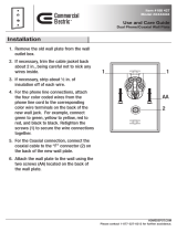
Figure 3. Ceiling Tile Installation
3. Remove an adjacent ceiling tile.
4. Connect the video cable/wires:
• BNC: Connect the BNC connector from the unit to a mating BNC connector.
• UTP: Blue wire = Video +
Gray wire = Video -
5. Connect the power wires.
AC operation only: If you are wiring more than one Camclosure to the same transformer, connect one
side of the transformer to the red wire on all units; connect the other side of the transformer to the
black wire on all units.
NOTE: Failure to connect all AC powered units the same way will cause the cameras to be out of
phase with each other and may produce a vertical roll when switching between cameras.
Voltage Red Wire Black Wire
12 VDC + Ground
24 VAC ~ ~
8-32 X 1.25-INCH
PHILLIPS FLAT
HEAD SCREWS
(SUPPLIED)
BACK BOX
CEILING TILE
ADAPTER PLATE

C3427M-C (10/07) 11
4S DEEP ELECTRICAL BOX
NOTE: You should install the camera module into the back box before installing the back box into the
surface. When installing the back box into the surface, rotate the camera module to access the mounting
holes (refer to Camera Module on page 12 for more information).
1. Attach the supplied adapter plate to the 4S box with two supplied 8-32 x 0.75-inch Phillips flat head
screws.
2. Pull video and power wires to the ceiling tile.
3. Connect the video cable/wires:
• BNC: Connect the BNC connector from the unit to a mating BNC connector.
• UTP: Blue wire = Video +
Gray wire = Video -
4. Connect the power wires.
AC operation only: If you are wiring more than one Camclosure to the same transformer, connect one
side of the transformer to the red wire on all units; connect the other side of the transformer to the
black wire on all units.
NOTE: Failure to connect all AC powered units the same way will cause the cameras to be out of
phase with each other and may produce a vertical roll when switching between cameras.
5. Attach the back box to the adapter plate with four supplied 8-32 x 0.375-inch Phillips flat head
screws.
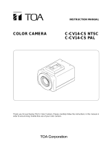
Figure 4. 4S Deep Electrical Box Installation
Voltage Red Wire Black Wire
12 VDC + Ground
24 VAC ~ ~
4S DEEP
ELECTRICAL
BOX
8-32 X 0.75-INCH
PHILLIPS FLAT
HEAD SCREW
(SUPPLIED)
8-32 X 0.375-INCH
PHILLIPS FLAT
HEAD SCREW
(SUPPLIED)
WALL OR
CEILING
ADAPTER PLATE
BACK BOX

12 C3427M-C (10/07)
Camera Module
The IS150 Series Camclosure camera module includes the camera, camera bracket, and heater board. To
perform most camera adjustments, you must remove the module from the back box.
Use the following instructions to remove and reinstall the camera module.
MODULE REMOVAL
To remove the camera module from the back box:
1. Gently squeeze the bracket and pull the module out of the back box (refer to Figure 5).
Figure 5. Camera Module Bracket
WARNING: Heater elements could be hot! When camera power is on, use caution when adjusting
the camera. This applies to all models.
BRACKET


14 C3427M-C (10/07)
CAMERA ORIENTATION
At the factory, the camera module is configured for ceiling mounting. For wall mounting, you must change
the camera orientation or the video image could be upside down or sideways.
To change the camera orientation (refer to Figure 7):
1. Remove the camera module from the back box if necessary.
2. Remove the tilt adjustment screw and lock washer from each side of the camera.
3. Carefully rotate the camera one quarter or one half turn, depending on desired camera angle.
NOTES:
• Make sure to orient the top of the camera to the top of the field of view.
• Make sure the wiring harness does not bind.
• Make sure to orient the service connector away from the back box.
4. Reinstall the tilt adjustment screw and lock washer on each side of the camera.
5. Verify the camera orientation.
Figure 7. Camera Orientation
MODULE INSTALLATION
To install the camera module into the back box:
1. Plug the connectors into the back box in the following order (refer to Figure 6 on page 13):
• Service (3-pin) connector
• Camera (10-pin) connector
• Heater board (4-pin) connector
2. Make sure the tabs on the camera bracket and the service connector are pointing out of the
enclosure, away from the ceiling or wall.
3. Gently squeeze the bracket, place it against the groove inside the back box, and gently release (refer
to Figure 5 on page 12).
TILT ADJUSTMENT
SCREW AND
LOCK WASHER
TOP
OF CAMERA
HEATER BOARD
TILT ADJUSTMENT
SCREW AND
LOCK WASHER
BOTTOM
OF CAMERA
HEATER BOARD

C3427M-C (10/07) 15
Camera Adjustments
To perform the following camera adjustments, make sure to plug in the camera and service connectors.
You may have to remove the camera module from the back box.
Connect a monitor. Then turn on power to the camera and monitor. To use the service connector, refer to
Service Connector on page 26.
To set the DIP switches, or to adjust the auto iris level (DN or CH) or the vertical phase (DW or CW), you
will need a miniature trimpot adjustment tool with a 0.05-inch (1.27 mm) blade. Suggested tools include a
miniature flat-tip screwdriver, a Philmore trimpot tool (#63-8608), and the Philmore 10-piece tool set
(#63-910). To adjust the lens, you may also need a miniature Phillips screwdriver.
After you have adjusted the unit, reinstall the camera module into the back box, and install the trim ring,
bubble, and liner (if necessary).
VARIFOCAL LENS ZOOM AND FOCUS ADJUSTMENTS
To adjust the field of view and the focus (refer to Figure 8):
NOTE: You may need a miniature Phillips or flat-tip screwdriver to loosen and tighten the locking screws.
1. Loosen the zoom locking screw.
2. Turn the zoom adjustment ring clockwise or counterclockwise to select the field of view.
3. Tighten the zoom locking screw.
4. Loosen the focus locking screw.
5. Turn the focus locking screw clockwise or counterclockwise to adjust the focus.
6. Tighten the focus locking screw.
Figure 8. Location of Zoom and Focus Adjustments
FOCUS
ZOOM

16 C3427M-C (10/07)
DN/CH SERIES ADJUSTMENTS
Refer to Figure 9 to adjust the IS150-DN or IS150-CH model.
Figure 9. Adjusting the IS150-DN/CH Series Camclosure
SWITCH SETTINGS
Locate the DIP switch. Then set the switches for your installation.
SW4-1: AGC (Auto Gain Control)
The AGC (automatic gain control) adjusts the image automatically to compensate for changes in light levels.
Set to ON to enable AGC. Set to OFF to disable AGC. The default is ON.
SW4-2: BLC (Backlight Compensation)
The BLC (backlight compensation) feature compensates for backlit scenes by enhancing objects in the center
of the scene.
Set to ON to enable BLC. Use this setting if a bright backlight is present and the subject in the center of the
picture appears dark or as a silhouette.
Set to OFF to disable backlight compensation. This is the default.
SW4-3: Line Sync
When multiple cameras are connected to the same switching device, vertical roll may occur on the monitor.
AC line lock eliminates vertical roll by locking the frame rate to the power supply frequency. Each camera
output is synchronized to the power supply frequency. (Refer to Vertical Phase Adjustment on page 18 for
more information.)
Internal line sync disables line lock and synchronizes cameras internally.
Set to OFF to use AC line lock. Set to ON to use internal line sync. The default is OFF.

C3427M-C (10/07) 17
SW4-4: Flickerless
In certain lighting conditions, a flicker in the light source may affect camera operation. Flickering can be
caused by a number of conditions, including the quality of the source power and the age and type of
fluorescent bulbs and ballasts.
Set to ON to enable flickerless operation. The camera will remove the effects of flickering when present.
The shutter speed will be set to 1/120 (NTSC) or 1/100 (PAL).
Set to OFF to disable flickerless operation. This is the default.
NOTE: If you enable flickerless operation, you should use AC line lock for best results.
SW4-5: AWB (Auto White Balance)/MWB (Manual White Balance)
Auto white balance is enabled by default (OFF).
To manually set and lock the white balance:
1. Set SW4-5 to OFF.
2. Hold a white background in front of the lens until the video shows all white.
3. While holding the background in place, set SW4-5 to ON. A blue blinking block appears on the video
image for a few seconds. When the block changes to solid green, the manual white balance process
is complete.
SW4-6: Reserved
Do not change SW4-6 from its factory setting. SW4-6 must be set to OFF for Varifocal models; it must be set
to ON for fixed-iris lenses.
AUTO IRIS LEVEL ADJUSTMENT
To adjust the auto iris DC-drive level (refer to Figure 9 on page 16):
1. Tilt or rotate the camera module until you can access the auto iris level control (R19).
2. Turn the screw clockwise to increase the brightness level or counterclockwise to decrease the
brightness level.

18 C3427M-C (10/07)
VERTICAL PHASE ADJUSTMENT
NOTE: Use this procedure for 24 VAC operation only.
When using more than one camera power supply, a brief vertical roll may occur on the monitor when
switching from one camera to another.
To eliminate vertical roll, reverse the 24 VAC connections on one camera. If both cameras are connected to
the same transformer, this should solve the problem. If the problem still exists, adjust the phase control by
synchronizing, or line-locking, the cameras to one another.
NOTE: When adjusting vertical phase, line sync (SW4-3) must be set to OFF for AC line lock.
Adjusting Vertical Phase
You may need two people when synchronizing the cameras: one at the camera, the other at the monitor to
observe the vertical roll and the effect of any camera adjustments.
To synchronize the cameras:
1. Choose a reference camera to which all other cameras will be phased.
2. Select the camera to synchronize. Use buttons SW1 and SW2 to synchronize the camera to the
reference camera (refer to Figure 9 on page 16). SW1 increases vertical phase; SW2 decreases
vertical phase.
3. Each time an adjustment is made, switch back and forth between the camera you are adjusting and
the reference camera. Repeat this process as many times as necessary until the roll between the
cameras is no longer noticeable.
4. Adjust the phase of all other cameras by repeating steps 2 through 3. Always adjust to the reference
camera selected in step 1.
NOTE: The preferred method for camera phase adjustment is to use a dual trace oscilloscope to align the
vertical sync pulses of the reference camera to the selected camera(s).
BLEMISH DETECTION
If small white or color spots appear in the video image, one or more pixels on the camera imager may be
defective. (This condition is common for both CCD and CMOS imagers.)
DN and CH Series cameras with auto iris lenses automatically detect and correct defective pixels during
startup. Video turns on, then off, and then on again. If white or color spots still appear, you can correct the
defective pixels manually.
CH Series cameras with fixed iris lenses do not automatically detect and correct defective pixels. You can
correct the defective pixels manually.
To manually correct defective pixels (refer to Figure 9 on page 16):
1. Cover the lens completely. Make sure no light can enter the lens.
NOTE: The mechanical iris lens aperture does not completely block the light.
2. Press and hold button SW3 for one second. The camera will find and correct defective pixels.
NOTE: Any defective pixels that cannot be completely corrected may still appear.
3. Release button SW3.
4. Uncover the lens for normal camera operation.

C3427M-C (10/07) 19
DAY/NIGHT OPERATION
NOTE: This section only applies to DN model cameras.
DN model cameras regularly check the brightness level of the field of view to determine when to switch
between day (color) and night (black-white) operation.
Actual brightness threshold levels are affected by camera angle, amount of zoom, field of view, lens, and
type of lighting. The switching process lasts from seven to 10 seconds.
Figure 10 and Table A show how the camera switches between color and black-white operation.
Figure 10. DN ModelsThreshold Switching Levels
NOTE: These switching thresholds are approximate. Use the thresholds in Table A as a guide when
installing the unit.
Table A. DN Models Switching Thresholds
Color to B-W 1.5 lux ±1.0 lux
B-W to Color 3.0 lux ±1.0 lux
B-W
MODE
COLOR
MODE
FALLING LIGHT LEVEL
RISING LIGHT LEVEL
B-W
MODE
COLOR
MODE
1.5 lux
3.0 lux

20 C3427M-C (10/07)
DW/CW SERIES (WIDE DYNAMIC RANGE) ADJUSTMENTS
Refer to Figure 11 to adjust the IS150-DW or IS150-CW model.
Figure 11. Adjusting the IS150-DW/CW Series Camclosure
SWITCH SETTINGS
Locate the DIP switch. Then set the switches for your installation.
SW1-1: Video Format
Set to ON for NTSC. Set to OFF for PAL. The default is ON.
SW1-2: Line Sync
When multiple cameras are connected to the same switching device, vertical roll may occur on the monitor.
AC line lock eliminates vertical roll by locking the frame rate to the power supply frequency. Each camera
output is synchronized to the power supply frequency. (Refer to Vertical Phase Adjustment on page 23 for
more information.)
Internal line sync disables line lock and synchronizes cameras internally.
Set to ON to use AC line lock. Set to OFF for internal line sync. The default is ON.
SW1-3: Interlaced Scanning/Progressive Scanning
Interlaced scanning is the standard for analog recording installations. Each frame contains one odd and one
even field, each processed separately.
Progressive scanning is better for digital recording installations. Each frame is processed as a whole,
which results in less blurring and cleaner digital conversion. It also saves storage space on digital video
recorders.
Set to ON to select interlaced scanning. Set to OFF to select progressive scanning. The default is ON.
DEFAULT SWITCH POSITION
R7
SW1
/