Page is loading ...

This manual must only be used by
a qualified heating installer / service
technician. Read all instructions,
including this manual along with
the Crest Installation and Operation
Manual, and the Crest Service Manual,
before installing. Perform steps in the
order given. Failure to comply could
result in severe personal injury, death,
or substantial property damage.
⚠WARNING
Save this manual for future reference.
100302418_2000555704 Rev C
Outdoor Crest Supplemental Manual
Models: OF 751 - 6001

2
CONTENTS
Hazard definitions
The following defined terms are used throughout this manual to bring attention to the presence of hazards of various risk levels or
to important information concerning the life of the product.
⚠ DANGER
⚠WARNING
⚠ CAUTION
CAUTION
NOTICE
DANGER indicates an imminently hazardous situation which, if not avoided, will result in death or serious
injury.
WARNING indicates a potentially hazardous situation which, if not avoided, could result in death or serious
injury.
CAUTION indicates a potentially hazardous situation which, if not avoided, may result in minor or moderate
injury.
CAUTION used without the safety alert symbol indicates a potentially hazardous situation which, if not
avoided, may result in property damage.
NOTICE indicates special instructions on installation, operation, or maintenance that are important but not
related to personal injury or property damage.
HAZARD DEFINITIONS .................................................. 2
PLEASE READ BEFORE PROCEEDING ..................... 3
THE OUTDOOR CREST -- HOW IT WORKS ............. 4-5
RATINGS .......................................................................... 6
1. DETERMINE BOILER LOCATION
Installation Must Comply With: ............................................ 7
Before Locating the Boiler, Check: ..................................... 7
Provide Clearances ............................................................. 8
Prevent Combustion Air Contamination .............................. 8
Remove Boiler from Wood Pallet ........................................ 8
Install Outdoor Vent Kit ....................................................... 9
Outdoor Venting ................................................................ 10
Outdoor Vent/Air Inlet Location ......................................... 10
2. GAS CONNECTIONS
Gas Supply ........................................................................ 11
Connecting Gas Supply Piping ....................................11-12
Natural Gas: ...................................................................... 12
Propane Gas: .................................................................... 12
Check Inlet Gas Supply .............................................. 13-14
Gas Valve Replacement ................................................. 14
3. START-UP
Pre-Commissioning Cleaning ........................................... 15
Fill Water ........................................................................... 15
Boiler Water...................................................................... 15
Oxygen Prevention .......................................................... 16
Check for Gas Leaks ........................................................ 16
Check Thermostat Circuit(s) ............................................. 17
Inspect Condensate System ............................................. 17
Final Checks Before Starting the Boiler ............................ 17
Start the Boiler .................................................................. 17
If Boiler Does Not Start Correctly ...................................... 17
Check System and Boiler .................................................. 17
Check Flame and Combustion .......................................... 18
Operating Instructions ....................................................... 19
4. DIAGRAMS
Ladder Diagram 751 - 2001 Models ................................. 20
Wiring Diagram 751 - 2001 Models .................................. 21
Ladder Diagram 2501 - 3501 Models ............................... 22
Wiring Diagram 2501 - 3501 Models ................................ 23
Ladder Diagram 4001 - 5001 Models ............................... 24
Wiring Diagram 4001 - 5001 Models ................................ 25
Ladder Diagram 6001 Model ............................................ 26
Wiring Diagram 6001 Model ............................................. 27
Revision Notes .................................................. Back Cover

Outdoor Crest Supplemental Manual
Please read before proceeding
Installer – Read all instructions, including
this manual, the Crest Installation and
Operation Manual and the Crest Service
Manual, before installing. Perform steps
in the order given.
User – This manual is for use only
by a qualified heating installer/
service technician. Refer to the User’s
Information Manual for your reference.
Have this boiler serviced/inspected by
a qualified service technician, at least
annually.
Failure to comply with the above could
result in severe personal injury, death or
substantial property damage.
Failure to adhere to the guidelines on this
page can result in severe personal injury,
death, or substantial property damage.
When servicing boiler –
• To avoid electric shock, disconnect electrical supply
before performing maintenance.
• To avoid severe burns, allow boiler to cool before
performing maintenance.
Boiler operation –
• Do not block flow of combustion or ventilation air to
the boiler.
• Should overheating occur or gas supply fail to shut off,
do not turn off or disconnect electrical supply to
circulator. Instead, shut off the gas supply at a location
external to the appliance.
• Do not use this boiler if any part has been under water.
The possible damage to a flooded appliance can be
extensive and present numerous safety hazards. Any
appliance that has been under water must be replaced.
When calling or writing about the boiler
– Please have the boiler model and serial
number from the boiler rating plate.
Consider piping and installation when
determining boiler location.
Any claims for damage or shortage in
shipment must be filed immediately
against the transportation company by
the consignee.
Factory warranty (shipped with unit) does
not apply to units improperly installed or
improperly operated.
3
If the information in this manual is not
followed exactly, a fire or explosion may
result causing property damage, personal
injury or loss of life.
This appliance MUST NOT be installed in
any location where gasoline or flammable
vapors are likely to be present.
WHAT TO DO IF YOU SMELL GAS
• Do not try to light any appliance.
• Do not touch any electric switch; do
not use any phone in your building.
• Immediately call your gas supplier
from a near by phone. Follow the
gas supplier’s instructions.
• If you cannot reach your gas supplier,
call the fire department.
• Installation and service must be
performed by a qualified installer,
service agency, or the gas supplier.
⚠WARNING
NOTICE
⚠WARNING
⚠WARNING

Outdoor Crest Supplemental Manual
4
The Outdoor Crest - How it works...
1. Front access panels
Provides access to the controls compartment.
2. Top access panel
Provides access to the burner compartment.
3. Optional outdoor air inlet hood assembly (shipped
separately with outdoor installation kits)
The hood assembly is required when installing outdoors for
combustion air to prevent rain and debris from entering the air
inlet.
4. Boiler drain connection
Location from which the heat exchanger can be drained.
5. Condensate drain connection
The condensate drain connection provides a connection
point to install a condensate drain line using flexible hose
provided.
6. Condensate trap box (shipped separately with outdoor
installation kits)
The condensate trap box comes assembled inside the outdoor
installation kit. The condensate trap box is required for
outdoor installations to protect/house the condensate trap.
7. Control module (on control panel assembly)
The control module responds to internal and external signals
and controls the blower, gas valves, and pump(s), depending on
the application, to meet the heating demand.
8. Electronic display
Digital controls with SMART TOUCH screen technology, full
color display, and an 8" user interface screen.
9. Gas connection pipe
The gas connection pipe is a threaded black iron pipe
connection (see Gas Connections Section for specific model
pipe size requirements). This pipe should be connected to the
incoming gas supply to deliver gas to the boiler.
10. Gas shutoff valve (inside unit)
The manual gas shutoff valve is used to isolate the boiler gas
train from the gas supply.
11. Gas valves
The gas valves sense the negative pressure created by the
blower, allowing gas to flow only if the gas valves are powered
and combustion air is flowing.
12. Condensate trap
The condensate trap is sized for a 1" PVC outlet connection
pipe.
13. Line voltage junction box
The line voltage junction box contains the connection points
for the line voltage power to the boiler (and pumps if used).
14. Line voltage wiring connections
Conduit connection points for the high voltage junction box.
15. Low gas pressure switch
Monitors gas supply pressure to the boiler and shuts the boiler
down in the event a low gas pressure condition
occurs.
16. High gas pressure switch
Monitors gas supply pressure to the boiler and shuts the boiler
down in the event a high gas pressure condition
occurs.
17. Low voltage connection board(s)
Connection boards used to connect external low voltage
devices.
18. Low voltage wiring connections (knockouts)
Conduit connection points for the low voltage connection
boards.
19. Power switch
The On/Off power switch provides the ability to turn line voltage
power to the boiler on and off.
20. Relief valve
The safety relief valve protects the heat exchanger from an over
pressure condition. The boiler comes with a 50 PSI relief valve as
standard equipment. Optional settings are available.
21. Reset switch
Reset switch for the low water cutoff. Hold the switch for 10
seconds to reset.
22. Test switch
The test switch permits manual triggering of the LWCO
safety circuit to test the contacts and evaluate the integrity of the
circuit. Hold the switch for 10 seconds to test.
23. Firetube heat exchanger
High grade stainless steel WAVE
TM
firetube design that extracts
heat from flue gases and transfers it directly into boiler water.
24. Temperature and pressure gauge
Monitors the outlet temperature of the boiler as well as the system
water pressure.
25. Venturi (not shown)
The venturi controls air and gas flow into the burner.
26. Water inlet
An ANSI flange connects the return water from the system to the
heat exchanger.
27. Water outlet
An ANSI flange connects the hot water supply from the boiler to
the system.
28. Flame inspection window (not shown)
Two large high temperature quartz observation windows
provide views of the burner surface during firing.
29. Air metering valve
The air metering valve is used to control the amount of air used
when firing.
30. Air metering valve air pressure switch
The air metering valve air pressure switch is used to ensure the air
metering valve is open when firing gas valve 2.
31. Vent support (shipped in the ship loose parts box with each
unit)
The vent support is required for outdoor installations to support
the vent piping.
32. Air pressure switch
The air pressure switch detects blocked flue/vent conditions.

Outdoor Crest Supplemental Manual
5
Right Side (inside unit)
The Outdoor Crest - How it works... (continued)
2000549892 0
0
2000549892
0
0
1
8
31
3
2
DIR #2000549892 0
0
Front View
DIR #2000549906 00
31
6
12
4
5
20
24
23
27
26
Rear View
DIR #2000549910 00
19
9
10
17
29
22
18
13
14
21
DIR #2000549908 00
15
16
11
30
32
7
Left Side (inside unit)

Outdoor Crest Supplemental Manual
Ratings
Outdoor Crest
AHRI Rating
Model Number
Note: Change “N” to
“L” for L.P. gas models.
Input
MBH
(Notes 4 - 8)
Min Max
Gross
Output
MBH
(Note 1)
Net
AHRI
Ratings
Water,
MBH
(Note 2)
OF(N,L)0751 50 750 720 626
OF(N,L)1001 50 999 960 835
OF(N,L)1251 62 1250 1200 1043
OF(N,L)1501 60 1500 1440 1252
OF(N,L)1751 70 1750 1680 1460
OF(N,L)2001 80 1999 1920 1670
OF(N,L)2501 125 2500 2403 2089
OF(N,L)3001 150 3000 2880 2504
OF(N,L)3501 175 3500 3360 2922
OF(N,L)4001 333 3999 3840 3339
OF(N,L)5001 500 4999 4800 4174
OF(N,L)6001 600 6000 5760 5009
Maximum allowed working pressure is located on the rating plate.
NOTICE
6
Notes:
1. The ratings are based on standard test procedures prescribed by the United States Department of Energy.
2. Net AHRI ratings are based on net installed radiation of sufficient quantity for the requirements of the building and nothing
need be added for normal piping and pickup. Ratings are based on a piping and pickup allowance of 1.15.
3. Standard Outdoor Crest boilers are equipped to operate from sea level to 4,500 feet only. The boiler will de-rate by 1.4% for
each 1,000 feet above sea level up to 4,500 feet.
4. Ratings have been confirmed by the Hydronics Section of AHRI.
5. Outdoor Crest boilers comply with the requirements of CSD-1 Section CW-400 requirements as a temperature operation
control. The manual reset high limit provided with the Outdoor Crest is listed to UL353.
Other Specifications
Boiler Water
Content
Gallons
Water
Connections
Gas
Connections
73 3" 1 1/4"
77 3" 1 1/4"
87 3" 1 1/2"
94 4" 1 1/2"
106 4" 1 1/2"
111 4" 1 1/2"
157 4" 2"
156 4" 2"
202 4" 2"
201 4" 2 1/2"
254 6" 2 1/2"
304 6" 2 1/2"

7
Outdoor Crest Supplemental Manual
1 Determine boiler location
The Outdoor Crest gas manifold and controls
met safe lighting and other performance
criteria when the boiler underwent tests
specified in ANSI Z21.13 – latest edition.
Do not install the unit under a deck.
Do not install the unit in a well, stairwell,
alcove, courtyard or other recessed area.
Do not install outdoor units on stack
frames. Failure to comply with the above
may result in severe personal injury, death
or substantial property damage.
Installation must comply with:
• Local, state, provincial, and national codes, laws, regulations,
and ordinances.
• National Fuel Gas Code, ANSI Z223.1 – latest edition.
• Standard for Controls and Safety Devices for Automatically
Fired Boilers, ANSI/ASME CSD-1, when required.
• National Electrical Code.
Before locating the boiler, check:
1. Check for nearby connection to:
• System water piping
• Gas supply piping
• Electrical power
2. - Keep venting areas free of obstructions.
- Keep area clean and free of combustible and flammable
materials.
- To avoid a blocked air inlet or blocked flue condition,
keep the outdoor air inlet and flue outlet clear of leaves,
debris, etc.
4. If a new boiler will replace an existing boiler, check for
and correct system problems, such as:
• System leaks causing oxygen corrosion or heat
exchanger cracks from hard water deposits.
• Incorrectly-sized expansion tank.
• Debris left from existing piping, if not flushed and
cleaned with an appropriate cleaner.
⚠WARNING
NOTICE
3. Check area around the boiler. Remove any combustible
materials, gasoline and other flammable liquids.
Outdoor models must be installed outdoors
only and must use the outdoor air inlet hood
assembly along with the vent termination
cap supplied by the manufacturer. Personal
injury or product damage may result if any
other venting is used or if an outdoor model
is used indoors. All covers, doors and jacket
panels must be properly installed to ensure
proper operation and prevent a hazardous
condition.
⚠WARNING
⚠WARNING
The unit must not be installed in an area
that is enclosed by walls or a fence that
will block free wind movement around
the appliance. Free movement of wind
around the outdoor unit is required
to carry away the flue products and
provide combustion air. The flue outlet/
combustion air inlet of an outdoor unit
must not be installed closer than 10 feet
from an inside corner of an L-shaped
structure. Walls or enclosed fencing may
cause eddy currents which can recirculate
the flue products into the combustion
air inlet. Recirculation of flue products
may cause operational problems, bad
combustion or non-warrantable damage
to controls.
Locate the unit at least 3 feet (0.91m)
outside any overhang.
⚠CAUTION
CAUTION
Do not install in locations where rain from
building runo drains will spill onto the
unit.
Do not locate the unit so that water
from sprinklers may spray directly onto
it. Water may damage controls or other
electrical components.
Failure to keep boiler area clear and free
of combustible materials, gasoline, and
other flammable liquids and vapors can
result in severe personal injury, death, or
substantial property damage.
⚠WARNING
This product contains a condensate
management and disposal system that
may be subject to freezing if exposed
to sustained temperatures below 32°F.
Precautions should be taken to protect
the condensate trap and drain lines during
extended periods of outdoor temperatures
below 32°F.
The Outdoor Crest is NOT suitable for
installation in areas which may experience
temperatures below 32°F.
⚠WARNING
Do not locate unit so that high winds can
deflect off of adjacent walls, buildings
or shrubbery causing recirculation.
Recirculation of flue products may cause
operational problems, bad combustion or
damage to controls. Locate unit at least
3 feet (0.91m) from any wall or vertical
surface to prevent wind conditions from
affecting performance.
⚠ CAUTION
Do not install outdoor models directly on
the ground. You must install the outdoor
unit on a level concrete, brick, block, or
pressure-treated wood platform.
CAUTION

8
Outdoor Crest Supplemental Manual
Products to avoid:
Spray cans containing chloro/fluorocarbons
Permanent wave solutions
Chlorinated waxes/cleaners
Chlorine-based swimming pool chemicals
Calcium chloride used for thawing
Sodium chloride used for water softening
Refrigerant leaks
Paint or varnish removers
Hydrochloric acid/muriatic acid
Cements and glues
Antistatic fabric softeners used in clothes dryers
Chlorine-type bleaches, detergents, and cleaning solvents
found in household laundry rooms
Adhesives used to fasten building products and other
similar products
Areas likely to have contaminants
Dry cleaning/laundry areas and establishments
Swimming pools
Metal fabrication plants
Beauty shops
Refrigeration repair shops
Photo processing plants
Auto body shops
Plastic manufacturing plants
Furniture refinishing areas and establishments
New building construction
Remodeling areas
Garages with workshops
Table 1A Corrosive Contaminants and Sources
Provide clearances:
Clearances from combustible materials
1. Hot water pipes—at least 1/4" (6 mm) from combustible
materials.
2. Jacket—minimum of 0" from right side and 14" from rear
side for proximity from combustible materials.
3. Vent—minimum of 1" from combustible materials.
Clearances for service access
1. If you do not provide the minimum clearances shown, it
may not be possible to service the boiler without removing
it from the space.
Prevent combustion air contamination
Do not install unit in locations that can allow contamination
of combustion air. Refer to Table 1A for products and areas
which may cause contaminated combustion air.
Under no circumstances is the manufacturer to be held
responsible for water damage in connection with this
appliance, or any of its components. If flooding is possible,
elevate the boiler sufficiently to prevent water from reaching
the boiler.
Recommended service clearances
Front: 30" (762mm)
Top: 24" (610mm)
Left side: 24" (610mm)
Right side: 24" (610mm)
Rear: 24" (610mm)
• This unit is not intended for installations where
temperatures may reach below 32°F (0°C). Exposure to
freezing temperatures will cause the system and boiler to
freeze and leak.
5. Check around the boiler for any potential air
contaminants that could risk corrosion to the boiler
or the boiler combustion air supply (see Table 1A).
Prevent combustion air contamination. Remove any of
these contaminants from the boiler area.
DO NOT install units in areas that contain
corrosive contaminants (see Table 1A).
Failure to comply could result in severe
personal injury, death, or substantial
property damage.
⚠WARNING
1 Determine boiler location
Flooring and foundation
Flooring
The Outdoor Crest is approved for installation on combustible
flooring.
Remove boiler from wood pallet
1. After removing the outer shipping crate and plastic from
the boiler, remove the parts package (packaged parts
inside the controls compartment of the boiler inside the
lower front access panel).
2. To remove the boiler from the pallet:
a. Remove the three (3) shipping bolts located inside
the controls compartment securing the boiler to the
front of the pallet (see FIG. 1-1 on page 9).
b. Remove the three (3) shipping bolts that fasten the
tie-down brackets securing the legs to the rear of the
pallet (FIG. 1-1).
c. The boiler can now be removed from the pallet
using a lift truck lifting from the front or rear of
the boiler. If lifting from the front, the lift truck
forks must extend at least half way under the boiler
heat exchanger to assure proper lifting technique
with no damage to the boiler.

9
Outdoor Crest Supplemental Manual
1 Determine boiler location (continued)
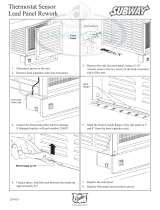
Install outdoor vent kit
In order to properly install the appliance in an outdoor
configuration, the optional outdoor kit must be used
(see Table 1B).
1. Locate all venting components from the installation kit
and carton.
a. Kit Components: Air Inlet Hood Assembly and
Condensate Trap Box Assembly
2. Position the air inlet hood assembly to the top of the unit.
Make certain the face of the wire screen frame of the hood
is set flush with the front leading edge of the top of the unit
as shown in FIG. 1-2.
3. Once positioned, use the kit provided self-tapping
fasteners to attach the hood to the unit through the
holes in the sides of the air inlet hood assembly.
Note: Once the air inlet hood is installed, the top, front and
side doors are still removable.
4. Locate the kit provided display cover and place over the
electronic display (FIG. 1-2).
5. Locate the kit provided condensate trap box.
6. The outdoor condensate wiring harness has escutcheons
built into it which allows a water tight fit into both the
rear jacket of the boiler as well as the terminal plates of
the condensate trap box. Connect the outdoor condensate
wiring harness to the pigtail connector of the condensate
trap (see FIG. 1-3).
7. Disassemble the condensate trap box.
Do NOT use grease or other lubricant on the
vent seals. Only water may be used for this
purpose. Grease or other lubricant can make
the seal brittle or cause tearing of the seal
surface which can result in flue gas leakage.
⚠CAUTION
Figure 1-2 Install the Air Inlet Hood Assembly
DIR #2000555428 00
DI
R
#2
00
0
AIR INLET HOOD ASSEMBLY
MAKE CERTAIN THE FACE
OF THE WIRE SCREEN
FRAME OF THE HOOD IS
SET FLUSH WITH THE
LEADING EDGE OF THE TOP
OF THE UNIT
PLACE THE DISPLAY COVER
OVER THE ELECTRONIC DISPLAY
Figure 1-3 Disassemble/Re-assemble outdoor condensate trap
DIR #2000555429 00
DISASSEMBLE
THE CONDENSATE
TRAP BOX
CONNECT THE OUTDOOR
CONDENSATE WIRING HARNESS
TO THE PIGTAIL CONNECTOR
8. Once the condensate hoses are inserted through the terminal
plates of the condensate trap box and attached to the
condensate trap (both inlet and vent), the condensate trap
box can then be re-assembled (FIG. 1-3).
9. Make certain the condensate trap is oriented correctly
and that the wiring harness has enough slack to ensure the
escutcheons remain seated properly. For proper trap
placement, reference the Condensate Disposal Section of the
Crest Installation and Operation Manual.
Failure to assure the truck forks are
long enough to extend at least halfway
under the boiler heat exchanger will
result in the boiler tipping off the lift
truck, and potentially falling. This will
result in severe personal injury, death, or
substantial property damage.
⚠WARNING
d. If lifting by crane is desired, remove the top access
panels to gain access to the lifting lugs located on
the boiler. It is also recommended that the upper
and lower front panels along with both front side
panels be removed (no tools required).
Do not drop the boiler or bump the jacket
on the floor or pallet. Damage to the
boiler can result.
DIR #2000555479 00
BOLT, WASHERS,
& LOCKNUT (3X)
LAG BOLTS & TABS (3X)
REARFRONT
Figure 1-1 Boiler Mounted on Shipping Pallet
NOTICE
Model Outdoor Kit Number
751 - 2001 100301827
2501 - 3001 100313289
3501 100308477
4001 - 5001 100313290
6001 100313291
Table 1B Outdoor Vent Kits

10
Outdoor Crest Supplemental Manual
1 Determine boiler location
Outdoor venting
• Vent materials for outdoor venting are to be field supplied.
• The vent must terminate at least 36 inches above the top of
the unit.
• All vent materials must be supported as recommended by
the vent manufacturer.
Before installing a venting system, follow
all requirements found in the Outdoor
Venting section of this manual.
NOTICE
Only install outdoor models outdoors,
and only use the vent caps specified in
this manual. Personal injury or product
damage may result if any other cap is used,
or if an indoor model is used outdoors.
Properly install all covers, doors, and jacket
panels to ensure proper operation and
prevent a hazardous condition.
Units are self-venting and can be used outdoors when installed
with the optional outdoor kit.
Combustion air supply must be free of contaminants To prevent
recirculation of the ue products into the combustion air inlet,
follow all instructions in this section.
⚠WARNING
For outdoor models, you must install a flue termination. Do
not install outdoor models directly on the ground. You must
install the outdoor unit on a concrete, brick, block, or other
non-combustible pad.
Keep venting areas free of obstructions. Keep area clean
and free of combustible and flammable materials. Maintain
minimum clearances to combustible surfaces and a 36"
(915 mm) minimum clearance to the air inlet. To avoid a
blocked air inlet or blocked flue condition, keep the air inlet,
flue outlet, and condensate trap clear of leaves, debris, etc.
Do not locate unit so that high winds can deflect off of
adjacent walls, buildings, or shrubbery causing recirculation.
Recirculation of flue products may cause operational
problems, bad combustion, or damage to controls.
Multiple unit outdoor installations require 48" (1.22 m)
clearance between each vent cap. Locate outdoor cap at
least 48" (1.22m) below and 48" (1.22 m) horizontally from
any window, door, walkway, or gravity air intake.
Locate unit at least 10 feet (3.05 m) away from any forced
air inlet.
Locate unit at least 3 feet (0.91 m) outside any overhang.
Clearances around outdoor installations can change with
time. Do not allow the growth of trees, shrubs, or other
plants to obstruct the proper operation of the outdoor vent
system.
Do not install in locations where rain from building runoff
drains will spill onto the unit.
Some discoloration to exterior building or unit surfaces can
be expected. Adjacent brick or masonry surfaces should be
protected with a rust resistant sheet metal plate.
Outdoor vent / air inlet location
Keep venting areas free of obstructions. Keep area clean
and free of combustible and ammable materials. Maintain
minimum clearances to combustibles as stated in this manual.
DO NOT install units in areas that contain
corrosive contaminants (see Table 1A on
page 8). Failure to comply could result in
severe personal injury, death, or substantial
property damage.
⚠WARNING

11
Outdoor Crest Supplemental Manual
2 Gas connections
Connecting gas supply piping
1. Refer to FIG. 2-1 to pipe gas to the boiler.
a. Install ground joint union for servicing, when
required.
Do not check for gas leaks with an open
flame – use the bubble test. Failure to
use the bubble test or check for gas leaks
can cause severe personal injury, death, or
substantial property damage.
3. Purge all air from the gas supply piping.
4. Before placing the boiler in operation, check the boiler
and its gas connection for leaks.
a. The appliance must be disconnected from the gas
supply piping system during any pressure testing of
that system at a test pressure in excess of 1/2 PSIG
(3.5 kPa).
b. The appliance must be isolated from the gas supply
piping system by closing a manual shutoff valve
during any pressure testing of the gas supply piping
system at test pressures equal to or less than 1/2 PSIG
(3.5 kPa).
c. The appliance and its gas connection must be leak
tested before placing it in operation.
⚠WARNING
5. Use pipe sealing compound compatible with propane
gases. Apply sparingly only to male threads of the pipe
joints so that pipe dope does not block gas flow.
Failure to apply pipe sealing compound
as detailed in the Crest Installation and
Operation Manual can result in severe
personal injury, death, or substantial
property damage.
⚠WARNING
Model Gas Inlet Size
OF0751 - OF1001 1 1/4"
OF1251 - OF2001 1 1/2"
OF2501 - OF3501 2"
OF4001 - OF6001 2 1/2"
Table 2A Gas Inlet Size
Gas supply
1. It is recommended to install one (1) gas regulator for each
Outdoor Crest boiler.
2. Gas regulators should be installed in a horizontal
orientation unless otherwise recommended by the
regulator manufacturer.
3. It is recommended to install a filter at the inlet of a gas
regulator to prevent debris from entering the regulator.
4. Gas regulators should be installed the greater of either 20
inches or 10 pipe diameters from the nearest fitting, elbow,
or valve to the outlet of the regulator.
5. It is recommended that the gas regulator outlet size match
the gas inlet size of the boiler and to not change the pipe
size between them. If the pipe diameter must be increased,
a bell reducer type fitting should be located at the regulator
outlet and the boiler inlet, maintaining the distance
indicated in Step 4.
6. Gas regulators must be properly vented to ensure proper
function:
a. Vent pipe must be no smaller than the regulator vent
connection size.
b. Each regulator must have a separate vent line.
c. Vent lines must not be combined together or with any
other equipment that also requires atmospheric vents.
d. Excessive gas regulator vent length will detrimentally
affect regulator performance:
• Gas regulators must be properly vented according to
the regulator manufacturer’s instructions.
• It is recommended that regulator vent length not
exceed 15 equivalent feet (4.5 m).
• When regulator vent must exceed 15 equivalent feet, it
is recommended to use a ventless regulator equipped
with a vent limiter.
• If a ventless regulator cannot be utilized, it is
recommended to increase vent diameter by one pipe
size after the initial 15 equivalent feet and every additional
10 equivalent feet.
e. Proper measures must be taken to prevent water,
snow, insects, or other debris from obstructing the vent.
Ensure that the high gas pressure regulator
is at least 10 feet (3 m) upstream of the
appliance.
NOTICE
2. Support piping with hangers, not by the boiler or its
accessories.
The gas valve and blower will not support
the weight of the piping. Do not attempt
to support the weight of the piping with
the boiler or its accessories. Failure to
comply could result in severe personal
injury, death, or substantial property
damage.
⚠WARNING
Figure 2-1 Gas Supply Piping
DIR #2000555433 00
GAS SUPPLY
UNION
SEDIMENT TRAP /
DRIP LEG CLEAN OUT
(FACTORY SUPPLIED)

12
Outdoor Crest Supplemental Manual
2 Gas connections
Use two wrenches when tightening gas
piping at boiler (FIG. 2-2), using one
wrench to prevent the boiler gas line
connection from turning. Failure to
support the boiler gas connection pipe
to prevent it from turning could damage
gas line components.
DIR #2000555453 00
USE BACK UP WRENCH TO PREVENT
PIPE FROM ROTATING
Figure 2-2 Inlet Pipe with Backup Wrench
3. Install 100% lockup gas pressure regulator in supply line for
each boiler if inlet pressure exceeds 14 inches w.c. (3.5 kPa).
4. Gas valves used on Outdoor Crest boilers are rated for at
least 27 inches w.c. (6.7 kPa).
Propane Gas:
Pipe sizing for propane gas
1. Contact gas supplier to size pipes, tanks, and 100% lockup
gas pressure regulator.
Propane Supply Pressure Requirements
1. Target a supply pressure of 11 inches w.c. (2.7 kPa)
measured when the boiler is operating at minimum input
rate. Gas pressure can be adjusted higher or lower than 11
inches w.c. as needed.
2. Adjust propane supply regulator provided by the gas
supplier for 14 inches w.c. (3.5 kPa) maximum pressure.
3. Pressure required at gas valve inlet pressure port:
• Maximum 14 inches w.c. (3.5 kPa) with boiler operating.
• Minimum 4 inches w.c. (.99 kPa) with boiler operating.
Maximum inlet gas pressure must not
exceed the value specified. Minimum
value listed is for the purposes of input
adjustment.
⚠WARNING
⚠WARNING
NOTICE
Check boiler rating plate to determine
which fuel the boiler is set for. Outdoor
Crest boilers CAN NOT be field converted.
Failure to comply could result in severe
personal injury, death, or substantial
property damage.
⚠WARNING
Check boiler rating plate to determine
which fuel the boiler is set for. Outdoor
Crest boilers CANNOT be field converted.
Failure to comply could result in severe
personal injury, death, or substantial
property damage.
Natural gas:
Pipe sizing for natural gas
1. Refer to Table 2B for pipe length and diameter. Based on
rated boiler input (divide by 1,000 to obtain cubic feet per
hour).
a. Table 2B is only for natural gas with specific gravity
0.60, with a pressure drop through the gas
piping of 0.3 inches w.c.
b. For additional gas pipe sizing information, refer to
the National Fuel Gas Code, NFPA 54 / ANSI Z223.1
- latest edition, or in Canada CSA B149.1 Installation
Code.
Natural gas supply pressure requirements
1. Target a supply pressure of 7 inches w.c. (1.7 kPa)
measured when the boiler is operating at minimum input
rate. Gas pressure can be adjusted higher or lower than 7
inches w.c. as needed.
2. Pressure required at the gas valve inlet pressure port:
• Maximum 14 inches w.c. (3.5 kPa) with boiler operating.
• Minimum 4 inches w.c. (.99 kPa) with boiler operating.
* GAS PRESSURE
REGULATOR
(FIELD SUPPLIED)
10'
MINIMUM
* MANUAL SHUT
OFF VALVE
(FIELD SUPPLIED)
* REQUIRED FOR INSTALLATION
IN THE COMMONWEALTH OF
MASSACHUSETTS
DIR #2000555541 00
Figure 2-3 Gas Supply Piping to Regulator

13
Outdoor Crest Supplemental Manual
Table 2B Natural Gas Pipe Size Chart
The gas piping must be sized for the proper flow and length of
pipe, to avoid excessive pressure drop. Both the gas meter and
the gas regulator must be properly sized for the total gas load.
If gas pressure drops more than 1 inch w.c. (249 Pa) between
maximum and minimum input rate, the meter, regulator, or gas
line may be undersized or in need of service. Perform the steps
below when checking inlet gas supply:
1. Turn the main power switch to the “OFF” position.
2. Shut off gas supply at the manual gas valve in the gas
piping to the appliance.
3. Remove the 1/8" pipe plug on the flange to the factory
supplied gas shutoff valve and install a suitable 1/8"
fitting (field supplied) for the manometer tubing. Place the
tubing of the manometer over the tap once the 1/8"
fitting is installed as shown in FIG. 2-4.
4. Slowly turn on the gas supply at the factory installed
manual gas valve.
5. Turn the power switch to the “ON” position.
6. Adjust the temperature set point on the control panel of
the SMART TOUCH control module to call for heat or
utilize Service Mode.
7. Observe the gas pressure with the burner
operating at 100% of rated input. Without turning
off the boiler, reduce the burner to the minimum input
rate and observe the gas pressure with the burner at
the minimum input rate. Percent of burner input will be
displayed on the Modulation Screen.
8. Ensure inlet pressure is within specified range.
Minimum and maximum gas supply pressures are
specified in this section of the manual.
9. If gas supply pressure is within normal range and no
adjustments are needed, proceed on to Step 11.
10. If the gas pressure is out of range, contact the gas utility,
gas supplier, qualified installer or service agency to
determine the necessary steps to provide proper gas
pressure to the control.
11. Turn the power switch to the “OFF” position.
12. Shut off the gas supply at the manual gas valve in the gas
piping to the appliance.
13. Remove the manometer from the pressure tap on top of
the gas valve. Remove the 1/8" (3 mm) field supplied
fitting and reinstall the pipe plug removed in Step 3.
DO NOT adjust or attempt to measure gas
valve outlet pressure. Attempting to alter
or measure the gas valve outlet pressure
could result in damage to the valve, causing
potential severe personal injury, death, or
substantial property damage.
⚠WARNING
TABLE - 2B
Capacity of Schedule 40 Metallic Pipe in Cubic Feet of Natural Gas Per Hour
(based on .60 specific gravity, 0.30" w.c. pressure drop)
Pipe
Size
(Inches)
Length of Pipe in Straight Feet
10 20 30 40 50 60 70 80 90 100 125 150 175 200
1 1/4 1,060 726 583 499 442 400 368 343 322 304 269 244 224 209
1 1/2 1,580 1,090 873 747 662 600 552 514 482 455 403 366 336 313
2 3,050 2,090 1,680 1,440 1,280 1,160 1,060 989 928 877 777 704 648 602
2 1/2 4,860 3,340 2,680 2,290 2,030 1,840 1,690 1,580 1,480 1,400 1,240 1,120 1,030 960
3 8,580 5,900 4,740 4,050 3,590 3,260 3,000 2,790 2,610 2,470 2,190 1,980 1,820 1,700
4 17,500 12,000 9,660 8,270 7,330 6,640 6,110 5,680 5,330 5,040 4,460 4,050 3,720 3,460
Check inlet gas supply
2 Gas connections (continued)

14
Outdoor Crest Supplemental Manual
⚠WARNING
Do not check for gas leaks with an open
flame -- use the bubble test. Failure to
use the bubble test or check for gas leaks
can cause severe personal injury, death, or
substantial property damage.
14. Turn on the gas supply at the manual gas valve.
15. Turn the power switch to the “ON” position.
16. Adjust the temperature set point on the control panel of
the SMART TOUCH control module to the desired
water temperature so the appliance will call for heat.
17. Check burner performance by cycling the system while
you observe burner response. The burner should ignite
promptly. Flame pattern should be stable. Turn system
off and allow burner to cool, then cycle burner again to
ensure proper ignition and flame characteristics.
Gas valve replacement
The gas valve MUST NOT be replaced with a
conventional gas valve under any circumstances. As
an additional safety feature, the gas valves have flanged
connections to the venturi and the blower.
Figure 2-4 Inlet Gas Supply Check
DIR# 2000549933 00
DO NOT adjust or attempt to
measure gas valve outlet pressure.
Attempting to alter or measure
the gas valve outlet pressure could
result in damage to the valve,
causing potential severe personal
injury, death, or substantial property
damage.
Failure to follow all precautions
could result in fire, explosion, or
death!
⚠WARNING
⚠WARNING
2 Gas connections

15
Outdoor Crest Supplemental Manual
3 Start-up
Check/control fill water chemistry
Conduct water quality testing prior to
installing the appliance. Various solutions
are available to adjust water quality.
Hardness between 5 and 12 grains per gallon
1. Consult local water treatment companies for hard water
areas (above 12 grains per gallon hardness).
2. Hardness levels that are above 12 grains/gallon can lead
to lime scale buildup throughout the boiler system. If the
fill water is below 5 grains/gallons, usually due to use of a
water softener, it is recommended to mix in some potable
water at the inlet to increase the hardness of the water to
above 5 grains/gallons.
pH between 6.5 and 8.5
1. pH levels below 6.5 can cause an increase in the rate of
corrosion. pH of 8.5 or higher can potentially cause lime
scale buildup.
Total Dissolved Solids (TDS) less than 350 ppm
1. Total dissolved solids are all minerals, salts, metals, and
charged particles that are dissolved in water.
2. The greater the amounts of TDS present, the higher the
corrosion potential due to increased conductivity in the
water.
Chloride concentration less than 150 ppm
1. Do not fill boiler or operate with water containing
chlorine in excess of 150 ppm.
2. Filling with fresh drinking water should be acceptable.
3. Do not use the boiler to directly heat swimming pool or
spa water.
IMPORTANT
Fill water
The manufacturer recommends the following for properly
filling your boiler with the appropriate water chemistry for
closed loop boilers. Good fill water quality will help extend
the life of the appliance by reducing the effects of lime scale
buildup and corrosion in closed loop systems.
Pre-Commissioning Cleaning
1. Prior to fill and start-up, flush the entire heating system.
2. Clean the entire heating system with an approved pre-
commissioning cleaner (comparable to Sentinel X300 or
X400 and Fernox F3 or DS40) in accordance with the
manufacturer’s recommendation to remove debris and
prolong the life of the heat exchanger.
3. Clean all water filtering devices in the system.
4. Flush the cleaning solution out of the entire system and
refill.
Boiler water
BOILER WATER CHEMISTRY
Speci cation Range
Dissolved Solids < 2000 ppm
pH Level 6.5 to 9.5
Chloride < 150 ppm
• Monitoring pH, chlorides, TDS, and hardness
levels can prolong the life of the appliance by reducing
lime scale buildup, corrosion, and erosion. Check for
leaks to ensure that fresh water is not entering the
system.
• Continual fresh makeup water will reduce boiler life.
• Mineral buildup in the heat exchanger reduces heat
transfer, overheats the stainless steel heat exchanger,
and causes failure.
• The addition of oxygen carried in by makeup water
can cause internal corrosion in system components.
• Leaks in the boiler or piping must be repaired at once
to prevent excessive makeup water. For this purpose,
it is recommended to install a water meter to easily
check the amount of makeup water entering the
system. Makeup water volume should not exceed 5%
of the total system volume per year. Note: When
makeup water is added, make sure the chemical
additives are added to maintain the correct level.
• An approved multi-metal corrosion inhibitor
(comparable to Sentinel X100 or Fernox F1) is
recommended at the correct concentration and in the
manner recommended by the manufacturer.
Do not use petroleum based cleaning or
sealing compounds in the boiler system.
Gaskets and seals in the system may be
damaged. This can result in substantial
property damage.
DO NOT use "homemade cures" or "boiler
patent medicines". Serious damage to
boiler, personnel, and/or property may
result.
Table 3A Boiler Water Chemistry

16
Outdoor Crest Supplemental Manual
3 Start-up
Oxygen prevention
Dissolved oxygen can have a negative effect on the boiler
system. Oxygen can cause iron oxide to generate iron deposits.
Oxygen may also increase the rate of corrosion on non-stainless
steel parts of the system. A low pH level combined with oxygen
further enhances its corrosive effects. After boiler installation,
check for air leaks in the following areas:
• Suction gasket
• Pump
• Air valve
• O-ring gaskets
Precautions include installing a water meter to evaluate the fresh
water volume entering the system (should be no more than
5% system volume). Additional volumes of fresh water could
indicate that a leak is present.
f. Open the isolation valves one zone at a time. Allow
water to run through the zone, pushing out the air.
Run until no noticeable air flow is present. Close
the zone isolation valves and proceed with the next
zone. Follow this procedure until all zones are
purged.
g. Close the quick-fill water valve and purge valve and
remove the hose. Open all isolation valves. Watch that
system pressure rises to correct cold-fill pressure.
h. After the system has operated for a while, eliminate
any residual air by using the manual air vents located
throughout the system.
i. If purge valves are not installed in the system, open the
manual air vents in the system one at a time, beginning
with the lowest floor. Close the vent when water
squirts out. Repeat with remaining vents.
2. Open the automatic air vent (diaphragm-type or bladder
type expansion tank systems only) one turn.
3. Open other vents:
a. Starting on the lowest floor, open air vents one at a
time until water squirts out.
b. Repeat with remaining vents.
4. Refill to correct pressure.
CAUTION
Eliminate all system leaks. Continual
fresh makeup water will reduce boiler
life. Minerals can build up in the heat
exchanger, reducing heat transfer,
overheating the heat exchanger, and
causing heat exchanger failure.
Fill and test water system
1. Fill system only after ensuring the water meets the
requirements of this manual.
2. Close automatic and manual air vents and boiler drain
valve.
3. Fill to correct system pressure. Correct pressure will vary
with each application.
a. The minimum cold water fill pressure for a system is
12 psi.
b. Pressure will rise when the boiler is turned ON and
system water temperature increases.
4. At initial fill and during boiler startup and testing, check
the system thoroughly for any leaks. Repair all leaks before
proceeding further.
Purge air from water system
1. Purge air from system:
a. Connect a hose to the purge valve. Route the hose to
an area where water can drain and be seen.
b. Close the boiler or system isolation valve between the
purge valve and fill connection to the system.
c. Close zone isolation valves.
d. Open the quick-fill valve on the cold water makeup
line.
e. Open purge valve.
Check for gas leaks
Before starting the boiler, and during
initial operation, smell near the floor and
around the boiler for gas odorant or any
unusual odor. Remove the top access
panel and smell the interior of the boiler
enclosure. Do not proceed with startup
if there is any indication of a gas leak.
Use an approved leak detection solution.
Repair any leaks at once.
DO NOT adjust or attempt to measure
gas valve outlet pressure. The gas valve is
factory set for the correct outlet pressure.
This setting is suitable for natural gas and
propane, requiring no field adjustment.
Attempting to alter or measure the gas
valve outlet pressure could result in
damage to the valve, causing potential
severe personal injury, death, or
substantial property damage.
⚠WARNING
⚠WARNING

17
Outdoor Crest Supplemental Manual
3 Start-up (continued)
Propane boilers only – Your propane
supplier mixes an odorant with the propane
to make its presence detectable. In some
instances, the odorant can fade, and the
gas may no longer have an odor. Before
startup (and periodically thereafter), have
the propane supplier verify the correct
odorant level in the gas.
Check thermostat circuit(s)
1. Disconnect the two external wires connected to the
enable terminals on the connection board.
2. Connect a voltmeter across these two incoming wires.
Close each thermostat, zone valve, and relay in the
external circuit one at a time and check the voltmeter
reading across the incoming wires.
3. There should NEVER be a voltage reading.
4. If a voltage does occur under any condition, check and
correct the external wiring. (This is a common problem
when using 3-wire zone valves.)
5. Once the external boiler enable wiring is checked and
corrected if necessary, reconnect the external thermostat
circuit wires to the connection board. Allow the boiler to
cycle.
Inspect condensate system
Inspect/check condensate lines and fittings
1. Inspect the condensate drain line, condensate PVC
fittings and condensate trap.
⚠WARNING
Final checks before starting the boiler
Read the Crest Service Manual to familiarize yourself
with SMART TOUCH control module operation. Read
this manual, page 19 for proper steps to start boiler.
Verify the boiler and system are full of water and all
system components are correctly set for operation.
Verify the preparation procedures of Section 3 pages 15 -
18 have been completed.
Verify electrical connections are correct and securely
attached.
Inspect vent piping and air piping for signs of deterioration
from corrosion, physical damage or sagging. Verify air
piping and vent piping are intact and correctly installed
per this manual.
Start the boiler
1. Read and follow the Operating instructions in FIG. 3-3,
page 19.
If boiler does not start correctly
1. Check for loose connections, blown fuse or service switch
off?
2. Is external limit control (if used) open? Is boiler water
temperature above 200°F (93°C)?
3. Is the boiler receiving a call for heat?
4. Is gas turned on at meter and boiler?
5. Is incoming gas pressure less than 4 inches w.c. (.99 kPa)?
6. Ignition problems are especially noticeable in new LP
installations and also in empty tank situations. This can
also occur when a utility company shuts off service to an
area to provide maintenance to their lines.
If none of the above corrects the problem, refer to the
Troubleshooting Section of the Crest Service Manual.
Check system and boiler
Check water piping
1. Check system piping for leaks. If found, shut down the
boiler and repair immediately. (See WARNINGS on
pages 15 - 18 (startup) regarding failure to repair leaks.)
2. Vent any remaining air from the system using manual
vents. Air in the system will interfere with circulation
and cause heat distribution problems and noise.
FROM CONDENSATE
VENT ON BOILER
FROM CONDENSATE
DRAIN ON BOILER
TO FLOOR DRAIN
OR NEUTRALIZER KIT
1" PVC / CPVC CONNECTION
Figure 3-1 Condensate Trap

18
Outdoor Crest Supplemental Manual
3 Start-up
Check vent piping and air piping
1. Check for gastight seal at every connection, seam, and
vent piping.
Venting system must be sealed gastight
to prevent flue gas spillage and carbon
monoxide emissions, which will result in
severe personal injury or death.
Check gas piping
1. Check around the boiler for gas odor following the
procedure on page 11 of this manual (connecting gas
supply piping).
If you discover evidence of any gas leak,
shut down the boiler at once. Find the
leak source with a bubble test and repair
immediately. Do not start the boiler again
until corrected. Failure to comply could
result in severe personal injury, death, or
substantial property damage.
Check flame and combustion
1. Turn the main power off to the boiler by placing the
“On/Off” switch in the OFF position.
2. Remove the fitting from the flue collector. Note:
Combustion measurements will be made at this point.
3. Insert the probe from a combustion analyzer into the
hole left by the removal of the fitting.
4. Turn the main power on to the boiler by placing the “On/
Off” switch in the ON position.
5. Navigate to the Setup Screen from the Home Screen
by pressing the SETUP button along the left side of the
screen. Enter the installer password.
6. Select the Service Maintenance Screen. The tabs will
scroll (up and down) to reveal more options.
On the Service Maintenance Screen place heater into
Service Mode by selecting the START button, then
selecting Set Gas Valve 1 - High (FIG. 3-2).
⚠WARNING
⚠WARNING
Table 3B Flue Products Chart
8. Once the heater analysis is complete, test the safety shutoff
device by turning the manual shutoff valve to the OFF
position and ensuring the heater shuts down and registers
an alarm. Open the manual shutoff valve and reset the
control.
9. Turn the main power off to the boiler and replace the
fitting into the flue pipe connection.
10. Ensure the boiler is placed back into normal operation.
You must replace the fitting to prevent flue
gas spillage into the room. Failure to comply
could result in severe personal injury, death,
or substantial property damage.
⚠WARNING
7. Once the boiler has modulated up to rate, measure the
combustion. The values should be in the range listed in
Table 3B (this page). CO levels should be less than 200
ppm for a properly installed unit. If the combustion is
not within range reference the Troubleshooting Section
in the Outdoor Crest Service Manual for possible causes
and corrective actions.
Figure 3-2 Service Maintenance Screen
Flue Products
Natural Gas
Units
751-2001 2501-6001
Gas Valve
CO
2
(%) O
2
(%) CO
2
(%) O
2
(%)
Valve 1 High 9.2 4.6 9.2 4.6
Valve 1 Low 9.0 4.9 8.5 5.7
Valve 2 High 9.3 4.4 9.5 4.2
Valve 2 Low 8.7 5.5 8.8 5.4
Propane
Units
751-2001 2501-6001
Gas Valve
CO
2
(% O
2
(%) CO
2
(% O
2
(%)
Valve 1 High 11.0 4.1 11 4.1
Valve 1 Low 10.0 5.6 9.9 5.7
Valve 2 High 11.1 4.0 11.1 4
Valve 2 Low 10.7 4.6 10.1 5.5
**All set points should be within +/- 0.2%**
SETUP

Outdoor Crest Supplemental Manual
19
FOR YOUR SAFETY READ BEFORE OPERATING
WARNING: If you do not follow these instructions exactly, a fire or explosion
may result causing property damage, personal injury, or loss of life.
A. This appliance does not have a pilot. It is
equipped with an ignition device which
automatically lights the burner. Do not try
to light the burner by hand.
B. BEFOR E OPER ATING smell a ll ar ou nd
the applia nce area for gas. Be sure to
smell next to the floor because some gas
is heavier than air and will settle on the
floor.
WHAT TO DO IF YOU SMELL GAS
• D o not try to light any appl iance.
• Do not touch any electric switch; do
not use any ph one i n your bui ldi ng .
• Immediately call your gas supplier from a
neighbor ’s phon e. Fol low the gas supp lier’s
instructions.
• If you can not reach your gas sup pl ier , call
the fire department.
C. Use only your hand to turn the gas control knob.
Never use tools. If the handle will not turn by
hand, don’t try to repair i t, call a qua lified se rvice
technician. Force or attempted repair may
result in a fire or explosion.
D. Do not use this appliance if an y part has been
under wa ter. Immed iate ly call a qu al ified
service technician to inspect the applianc e and
to replace any part of the control system and
any gas control w hich has been under wa ter.
OPERATING INSTRUCTIONS
1. STOP! Read the safety information
above on this label.
2. Set the thermostat to lowest setting.
3. Turn off all electric power to the
applianc e.
4. T his appliance is equipped with an
ignition device which automatically lights
the burner. Do not try to light the burner
by hand .
5. Remove front door.
6. Turn gas shutoff valve counterclockwise
to “OFF”. H andle wil l be perpendicu lar to
pipe. Do not force.
7. Wait five (5) minutes to clear out any gas.
If you then smell gas, STOP ! Follow “B”
in the safety information above this label.
If you don’t smell gas, go to next step.
8. Tur n gas sh utoff val ve clockwise to “ON”.
Handle will be parallel to pipe.
9. Instal l fr ont doo r.
10. Turn on all electric power to appliance.
11. Set ther mostat to desire d setti ng.
12. If the ap pl iance w ill n ot oper ate , fol low th e
instructions “To Turn Off Gas To Appliance” and
call your service technician or gas supplier.
TO TURN OFF GAS TO APPLIANCE
1. Set the thermostat to lowest setting.
2. T urn off all e lectric po wer to the ap pl iance
if service i s to be perfor med.
3. Remove front door.
4. Turn gas shut off valve counterclockwise to
“OFF”. Handle will be perpendicular to pipe.
Do not force.
5. Instal l fr ont doo r.
L BL2 005 3 REV B
Figure 3-3 Operating Instructions
3 Start-up (continued)

20
Outdoor Crest Supplemental Manual
4 Diagrams
Figure 4-1 Ladder Diagram_751 - 2001 Models
TERMINAL STRIP
TERMINAL STRIP
16
15
13
12
11
10
9
6
5
3
2
1
39
36
35
33
32
31
30
29
26
25
23
22
21
20
19
OUTLET SENSOR (S9)
OUTLET SENSOR (S1)
FLUE SENSOR
FLUE SENSOR (S10)
120VAC
NEUTRAL
ON/OFF
SWITCH
GAS
VALVE
(LARGE)
GAS
VALVE
(SMALL)
CONTACTOR
BOILER PUMP
CONTACTOR
DHW PUMP
CONTACTOR
BLOWER
BLOWER
1
2
3
BAS (AS APPLICABLE)
FLUE DAMPER
TRANSFORMER
1
2
3
TRANSFORMER
FLUE DAMPER
TEST
SWITCH
LWCO
PROBE
LWCO RESET
GPS1 GPS2
BLOCKED FLUE
SWITCH
BLOCKED DRAIN
SWITCH
ALARM
CONTACTS
CONTACTS
TANK
THERMOSTAT
LOUVER
PROVING
AUX
SWITCH 1
AUX
SWITCH 2
ENABLE
R
W
FLAME
SENSE 1
FLAME
SENSE 2
SPARK
GENERATOR
SPARK
ROD
SHIELD
SHIELD
A
B
BAS
OPTION
RATE
OUT
BOILER
PUMP OUT
SENSOR
SENSOR
TANK
SENSOR
OUTDOOR
SENSOR
BMS
IN
PUMP IN
SHIELD
SHIELD
A
B
CASCADE
INLET SENSOR
GROUND
1
2
5
BLOWER
BOX DEPICTS
OPTIONAL ITEMS
BOX DEPICTS
DUAL SENSOR
SINGLE HOUSING
HIGH VOLTAGE
LOW VOLTAGE
120 VAC
"X5"
BLOCK WIRING
IS MODEL
DEPENDENT
AIR VALVE
PRESS. SWITCH
BLOWER
AIR VALVE
HIGH LIMIT
SWITCH
M
M
DISCONNECT POWER
BEFORE SERVICING
BOILER PUMP
DHW PUMP
5.0 A
3.15 A
F2
LARGE GAS
LARGE GAS
SMALL GAS
SMALL GAS
USB
INTERFACE
X11
WIFI
DONGLE
USB CABLE
SW1
LG CON BRD
OPTIONAL
ETHERNET CABLE
OPTIONAL USB/WIFI
EXTENSION CABLE
BAS
E
GND
BAS
BOARD
(AS
APPLICABLE)
SHIELDED CABLE FROM X4
TO J12 OR J23 AS APPLICABLE
Notes:
1. All wiring must be installed in accordance with: local, state, provincial and national code requirements per either N.E.C.
in USA or C.S.A. in Canada.
2. If any original equipment wire as supplied with the appliance must be replaced, it must be replaced with wire having same
wire gauge (AWG) and rated for a minimum of 105°C. Exceptions: Replacement high voltage spark lead and
shielded
cables
must be purchased from the factory. Use of a non-approved spark lead or
shielded
cables can lead to operational problems
which could result in non-repairable damage to the integrated controller or other components.
3. Actual connector block locations may vary from those shown on diagrams. Refer to actual components for proper
connector block locations when using diagrams to troubleshoot unit.
LADDER DIAGRAM
100266646 REV B
/